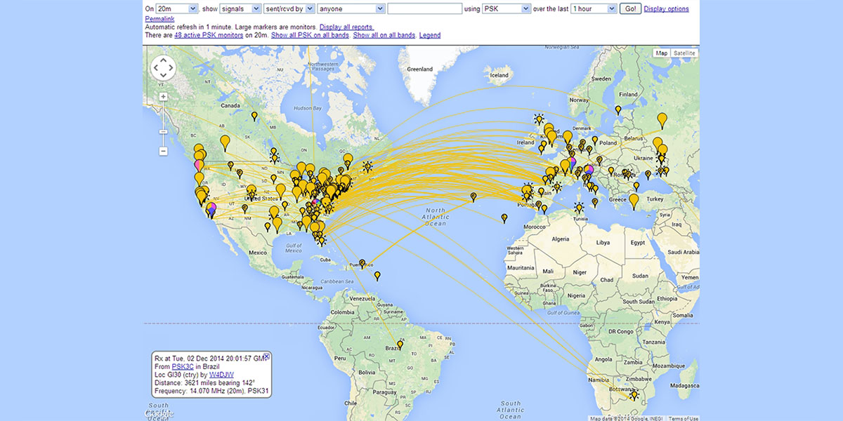
Listening to shortwave radio is very interesting, and filled with the voices and music of far-off lands. Digging a bit deeper, there is another world of shortwave radio that does not use conventional sounds. It is the realm of data transmissions. As amazing as it seems, many of these data signals can be picked up and decoded at home using just a low cost shortwave receiver, your PC, and some specialized software. If you are connected to the Internet, your radio receptions can be reported to websites like PSKreporter.info, WSPRnet.org, and others where they will be displayed on a world map such as PSK Reporter as shown in the lead photo. In this article, I will show you how to use a low cost ($62) shortwave radio to get you started in this exciting hobby.
Data transmissions vary in complexity and contain a wide variety of information. Some are as simple as Morse code (CW) or Radio-teletype (RTTY), while others are more sophisticated such as AMTOR or SITOR which are similar to RTTY.
Some of the popular newer modes are Binary Phase Shift Keying (BPSK), Weak Signal Propagation Reporter (WSPR), and the weak signal digital modes JT65/9. These modes — developed by amateur radio operators — use low power and complex coding, and allow communication over great distances. Text messages are usually conveyed with these protocols. To convey images and graphics, commercial stations use radio-facsimile (FAX), while amateur stations use slow scan TV (SSTV) and EasyPal.
One of the things that all of these modes have in common is that they are audio modes. That is, the radio signals are first converted to audio signals using your radio receiver. Then, the sound is analyzed using audio decoders in the PC software. Figure 2 shows how the pieces fit together.
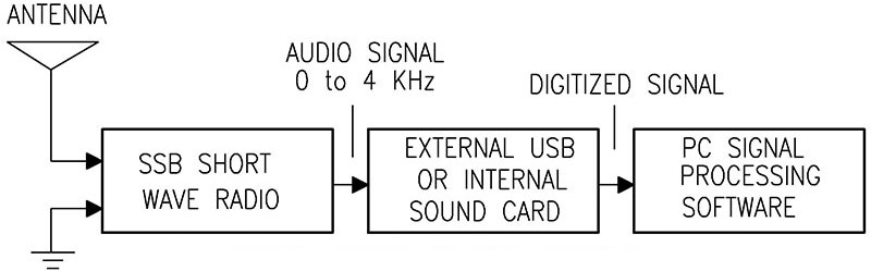
FIGURE 2. Block diagram of shortwave data receiver.
What makes this setup work nicely is that most PCs have sound cards that can accept the audio signals from the radio. If yours does not, you can add an inexpensive USB sound card to do the job. Then, to decode the audio, it is only a matter of selecting the right software for the mode of interest.
Several software packages will be discussed to help you get started. The good news is that most of it is free and can be downloaded from the Internet.
Selecting Your Shortwave Receiver
The basic requirements for your radio are that it be stable, have a numerical frequency readout, and receive SSB (single side band) signals. Many commercial or ham radios will do the job, but can be expensive. One popular low cost receiver that fits the bill is a DEGEN Model DE1103 as shown in Figure 3. It can be found on the Internet for around $62 and works well in this application.
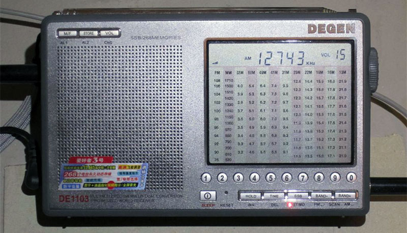
FIGURE 3. DEGEN Model 1103 SSB radio.
This model stabilizes in a few minutes, has a jack for an external antenna, has digital frequency readout, and a BFO (beat frequency oscillator) for receiving SSB signals. Its small size and battery operation make it easy to take on vacations along with your laptop PC. This allows you to enjoy the hobby away from home.
Setting Up Your Shortwave Antenna
The single most important component of your setup is the antenna. Ideally, it should be a resonant antenna such as a dipole that is cut for the frequency range of interest. However, a long wire antenna placed as high as possible will work well even if it is not perfectly matched. The main thing is to get it up high and away from noise sources, like your PC.
The DE1103 has an external 3.5 mm antenna jack on the side of the case for shortwave. Unlike more costly radios that provide a 50 ohm antenna jack, the DE1103 impedance varies from 1,000 ohms at 4 MHz to 200 ohms at 14 MHz. You can use a single wire or shielded coaxial cable to connect your antenna to this jack. If you use coax, you will need to make a cable with a 3.5 mm plug on the end. To reduce noise, an antenna tuner or pre-selector can be used between the radio and the antenna.
A good ground system is very important. Try to connect your radio ground to the earth ground in your home. Failing that, use a long wire along the floor to act as a counter-poise or substitute for earth ground.
Connecting the Audio
The audio signal from your radio needs to be connected to the PC sound card line-input. If you are using an external USB sound card, use a USB cable with built-in noise suppression to prevent computer noise from getting to the radio. To connect the audio, look for the audio-out jack on the radio.
Most radios have a provision for connecting to headphones or an external speaker. For the DE1103, the connection is easy as there is a line-out jack on the side of the radio. Finally, you need to know how to adjust the line-input level in the sound card recording section of your PC.
Getting to Know Your Receiver
Spend some time getting acquainted with your receiver’s operating controls. There will generally be controls to select the audio bandwidth, adjust the frequency, select the SSB mode, and adjust the BFO frequency. For the DE1130, the narrow-wide switch selects either 4 kHz or 6 kHz wide audio. In most cases, use the wide setting as powerful audio filters in the software will filter the noise. To select the desired radio frequency in kHz, enter the desired digits, press BAND+, and select SSB.
With this radio — as with many radios — you can only select the frequency to the nearest kHz since only the five most significant digits can be entered. That’s okay for receiving AM stations, but for receiving SSB voice signals smaller frequency adjustments need to be made. This is done via the BFO knob on the side of the unit.
Understanding the BFO
The BFO effectively provides variable adjustment of about 1.5 kHz above and below the dial frequency as seen in Figure 4. It is usually un-calibrated, however. In other words, the last — or lesser — three digits of the true dial frequency setting are unknown. More frequency precision needed for data transmissions can be achieved by calibrating the BFO.
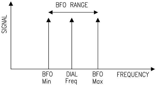
FIGURE 4. Variation of received frequency with BFO.
Typically, seven digits of frequency are needed to locate specific radio bands and for accurate signal reporting. Thus, we need to determine the true RF receiving frequency of the radio when using SSB and the BFO together.
For my DE1103, the BFO knob allows frequency adjustment of plus 1,600 Hz to minus 1,300 Hz from the displayed dial frequency. The maximum BFO frequency (1,600 Hz) is attained with the BFO knob set fully counter-clockwise (CCW). Turning the knob CW from the fully CCW position causes a decrease in the BFO frequency, gradually reducing it to 0 Hz and then further to -1,300 Hz.
Here is an example of how the BFO affects the true radio dial. Suppose the displayed radio dial is 14,020 kHz and the BFO is set to +755 Hz. Adding the two, the true dial setting would be 14020.755 kHz (14.020755 MHz). In this example, we now have eight digits of frequency. In practice, the last digit will not be known to high accuracy. However, it will be good enough to get us to the right shortwave band segments — usually within 10 Hz.
If the BFO knob was calibrated in frequency, this would be the end of the story. Most BFOs — particularly in low cost radios like the DE1103 — are not. Another problem is that the BFO frequency will change a small amount with dial frequency. The good news is that we can easily overcome these problems using an audio spectrum analyzer on our PC and two standard candle radio stations separated widely in frequency.
These standard candle radio stations can be an AM radio station near 1,000 kHz and a shortwave station like WWV at 10 MHz. WWV has a very accurate frequency, and AM stations are required to be within 20 Hz of their assigned frequency. This allows us to perform a calibration for our radio’s BFO. It is easy and fun. Here’s how to do it.
Calibrating Your BFO on SSB
First, get an audio spectrum analyzer (SA) running on your PC. A good choice is the free program SpectrumView from WD6CNF. It will be assumed here that your radio audio output is connected to the sound card on your computer and SpectrumView is running. Allow the radio to warm up to reduce drift. Remember there are two things we want to find: the BFO frequency and how it changes with frequency.
It’s easy to determine the BFO frequency. Tune in a local AM station of known frequency and select SSB on the receiver. There will be an audio tone and a peak in the audio spectrum as shown in Figure 5. This peak is due to the carrier of the AM station. Adjust the BFO knob back and forth, and watch the tone peak move left or right. The peak frequency is shown at the top of display. This tone peak is the BFO frequency.
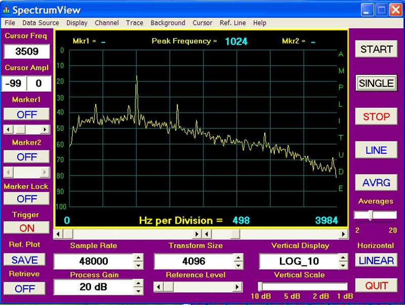
FIGURE 5. SpectrumView audio spectrum analyzer.
Okay, now we want to find out how the BFO changes with RF dial frequency. We can do this by tuning in another station far away in frequency from the AM station and noting the change in BFO frequency. A good choice is WWV at 10 MHz as previously mentioned. (In a pinch, an RF signal generator can be used in place of WWV.)
Let’s say that we tuned to a local AM station at 1.130 MHz and set the BFO to 970 Hz by observing SpectrumView. Then, say, we tuned to WWV at 10 MHz and found the BFO peak had changed to 1,024 Hz. This shows that the BFO increased 54 Hz over the 8.87 MHz frequency difference between the two stations. This is a rate of 6.08 Hz per MHz. It is a small change, but worth correcting for in the interest of accuracy. (Your AM station frequency and numbers, of course, will be different.) Remember this rate value. It is all we need to set the BFO to any value at any frequency.
Here is an example of how to do this.
Suppose we wish to set the BFO to 600 Hz at 14.095 MHz. (Note that this corresponds to the true dial of 14.095600 MHz in SSB mode.) We will use the standard candle AM station at 1.130 MHz. Note the frequency difference (14.095 – 1.130) = 12.965 MHz. Hence, the BFO frequency at 1.13 MHz would correspond to 600 – 6.08 x 12.965 = 521.1 Hz.
At this point, tune in the AM station at 1.130 MHz in SSB mode and adjust the BFO knob for 521 Hz. Now, when you set 14.095 on the radio dial, it will correspond to BFO of 600 Hz and the true dial frequency of 14.095600 MHz. In this case, the AM station is our standard candle, and since it is a local station it is always available for setting the BFO using SpectrumView. Station WWV is no longer needed.
Note that the BFO setting can be a negative frequency. Suppose you want a BFO setting of 0 Hz at 14.076 MHz which is a true dial frequency of 14.076000 MHz. Similar to above, we have 0 – 6.08 x 12.946 = -78 Hz. For this case, just rotate the BFO knob past 0 Hz to negative frequencies, as monitored by SpectrumView at the standard candle of 1.13 MHz.
Once the BFO is set, do not adjust it except to change to another effective dial setting. It may drift a little with temperature, so check it periodically. Remember that SSB mode must be selected to use it. BFO calibration is very useful for selecting the starting radio frequency segments for BPSK, WSPR, and JT65, which usually need an accurate true dial setting.
Since many of the signals you will be receiving are barely audible, this procedure puts you on the right frequency.
Grid Squares
A geographic coordinate system used by amateur radio operators and others around the world is the Maidenhead Locator System (MLS). It is also commonly referred to as grid locators or grid squares. The MLS compresses latitude and longitude into a string of characters to allow position information to be transmitted with limited precision. This is very useful when determining distances and angles of radio transmissions.
Many web logging sites such as PSKreporter and WSPR use grid squares. Most data decoding programs have means to automatically send grid squares, as well as frequency information, call sign, or name directly from the program. So, if you are connected to the Internet and want to provide signal reports, make sure to enable that feature in the program, and have your specific grid square and other information entered properly. To find your specific grid square, go to www.levinecentral.com/ham/grid_square.php and enter your zip code or city. For example, Chicago has the grid square EN61ev.
CW, RTTY, and BPSK
In my opinion, the best program for receiving CW, RTTY, and BPSK is Fldigi (Fast and Light Digital Modem Program). Figure 6 shows Fldigi in action receiving SITORB. It is a free program developed by radio amateurs. It handles many other modes as well, and has numerous features including a built-in spectrum display and audio filters. You can also enter your frequency, call sign, or name, and enable automatic reporting to PSKreporter.
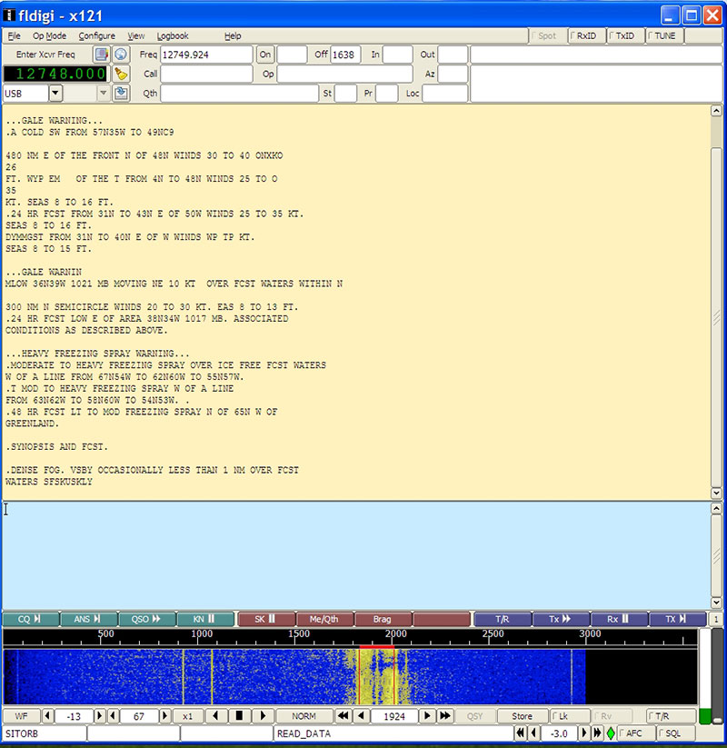
FIGURE 6. SITOR data received with Fldigi software decoder.
Fldigi can be downloaded from www.w1hkj.com/Fldigi.html. Check the Internet for frequencies where these modes can be found. For example, PSK-31 can be found at 14.070000 MHz and SITOR at 12.577000 MHz.
WSPR, JT9, and JT65
These modes are used for weak signal communication. Oftentimes, these signals are so weak they are not perceptible by ear. These modes are used in special segments of the ham bands. For example, WSPR can be found on 14.095600 MHz, and JT65 can be found on 14.076000 MHz. Note the precision of the dial settings; see Figure 7 for a JT65 screenshot.
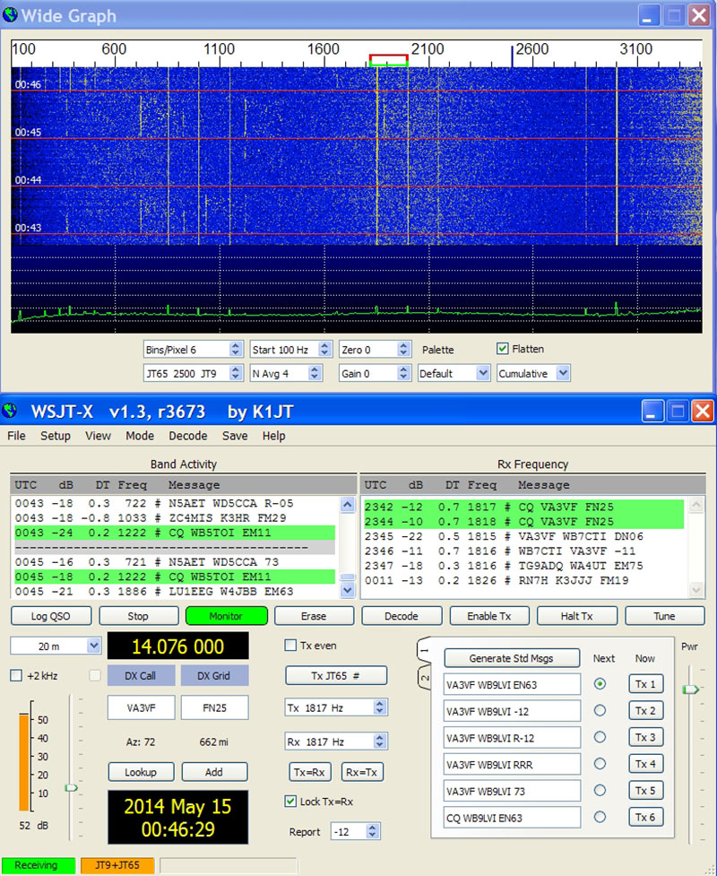
FIGURE 7. JT65 decoding windows.
Included with the programs are dial frequencies for all bands. WSPR has its own website for reporting spots, while JT9/JT65 uses PSKreporter. These programs can be found at www.physics.princeton.edu/pulsar/K1JT.
These weak signal modes require coordination of your PC with Universal Coordinated Time (UTC) to within one or two seconds. So, make sure to set your computer clock accordingly, and check it often.
Software for FAX, SSTV, and EasyPal
FAX can also be received with Fldigi. An example of a noisy weather fax is shown in Figure 8. Fax signals can often be found around 12.748 and 12.788 MHz. Slow scan TV signals can be found around 14.230 MHz. Several programs are available on the Internet for SSTV.
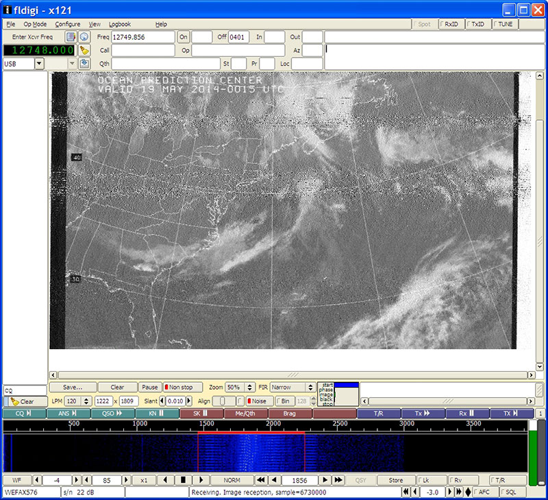
FIGURE 8. Weather FAX image received with Fldigi.
One of the newer picture modes is EasyPal, which transmits pictures digitally. It can be found at 14.233 MHz. Perfect pictures can be received if the signal manages to make it through the noise. Search for it on the Internet.
Final Comments
Hopefully, you have learned a little bit about how to receive and decode shortwave data signals. It is a very interesting hobby, and new modes are cropping up all the time. If you find the subject of decoding radio signals fascinating, you may want to consider becoming a radio amateur. Hams are involved with building and studying receivers, transmitters, and antennas, and experimenting with the radio modes WSPR, JT65, and BPSK discussed here.
If you are considering joining the fraternity of radio amateurs, the ARRL website is the place to start. In the meantime, have fun with your shortwave radio decoder. NV