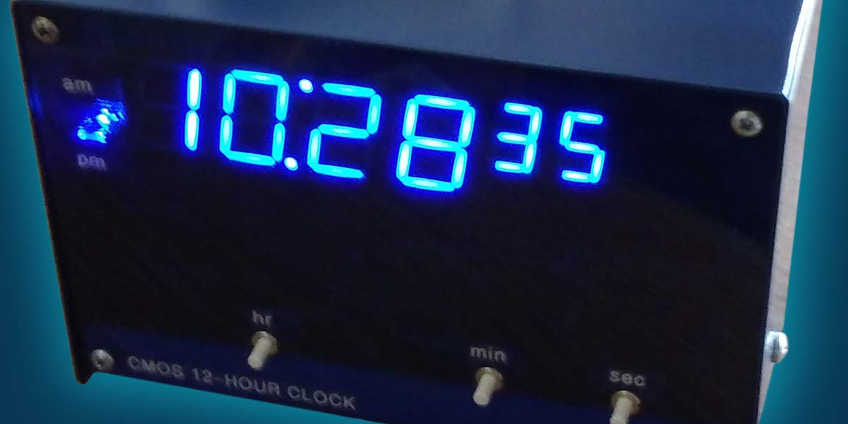
Previously, I described an old-school 12 hour digital clock that employed discrete CMOS logic. That clock displayed minutes and hours on four seven-segment displays, with the pairs of displays separated by a blinking colon. The time was identified by three counters, each driving a decoder and one display and two flip-flops: one for the hours 10s digit and one for two LEDs alternately indicating morning and afternoon.
A time base using a crystal-controlled oscillator provided several signals: 1/minute to drive the counter chain; 1 Hz for the colon; and faster signals for setting the clock. Figure 1 shows that unit’s general design; it’s typical of such clocks. The minutes 10s digit is inverted so that its decimal point forms half of a colon between the hours and minutes.
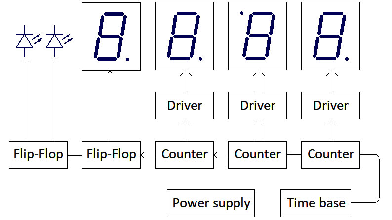
Figure 1. Typical design of a discrete logic clock.
There are many variations on this theme that experimenters and builders may find interesting. Following are several of these variations and some suggestions for building discrete logic clocks.
The Time Base
Any crystal frequency can be used in the time base so long as it can be divided down to provide the frequencies a clock requires. The tools available here include binary ripple counters (sequences of flip-flops) like the CD4020 and CD4060, and decimal and binary counters like the CD4510, 74LS90, 74LS161, and many others.
Suppose, for example, that our junk box yields a crystal whose frequency is 3.072 MHz and we desire a 1 Hz signal. The prime factorization of 3,072,000 is 213 x 3 x 53. Rearranging the factors to match various counters, we get 3,072,000 = 211 x 102 x 15. We can generate a 1 Hz signal from the output of an oscillator based on this crystal with, say, 11 stages of a CD4020 to divide by 211; a CD4518 dual BCD up-counter to divide by 10 twice; and a CD4516 binary counter with additional logic so that it resets when it reaches a count of 15 rather than 16.
These stages can occur in any order, so we can choose appropriate higher-frequency signals for setting. Dividing the 1 Hz signal by 60 = 6 x 10 yields one pulse every minute to drive the counters that identify the time’s digits.
Crystal frequencies that include larger prime factors should be avoided. It’s inconvenient to try to divide by, say, 23. Powers of 2 like 4.194304 MHZ are the easiest to divide down. Just use the requisite number of stages in a binary ripple counter.
The necessary signals can also be derived from the 60 Hz line frequency. Assuming a low-voltage transformer powers a clock, the transformer’s output is rectified separately from the clock’s power supply — but not filtered — and run through a Schmitt trigger; there will be noise on the line, and we don’t want extra pulses.
The trigger can be an inverter in any of several chips, based on a TLC555 or an op-amp, or built from discrete components. The resulting signal will be divided by 60 to 1 Hz and by 60 again to 1/minute.
An elegant device that divides by 60 is the 74LS57: an eight-pin DIP integrated circuit that was designed for use in clocks. (The 74LS56 divides by 50, for clocks in 50 Hz systems). Two of these yield a 1/minute signal from the line frequency and take up little space on a board. The 74LS57 is, however, very hard to find and so probably not a viable choice.
Certainly, one can twice divide by 10 and by 6, using, say, 74LS90s or other BCD counters and two 74LS92s, or using BCD or binary counters and some additional logic to reset two of them when they reach 6 (and 10 if necessary). Noting that 3600 = 152 x 16, another solution uses two binary counters and additional logic to each divide by 15, and a third binary counter to simply divide by 16.
Figure 2 shows such a circuit using three 74LS193 up/down binary counters with 60 Hz input and outputs of 60 Hz, 4 Hz, 1 Hz, and 1/minute. The first and third counters count down from 15; they are reset to ‘1111.’ The middle counter counts up to 16. In general, external logic can be used to reset any counter when it reaches a specified count less than 10 or 16.
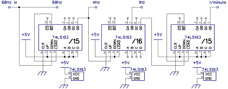
Figure 2. A circuit that divides a 60 Hz input down to 1/minute. It divides the input frequency by 15, by 16, and then by 15 again.
Seconds
A useful extension of the design above accepts an input signal of 1 Hz and displays seconds as well as minutes and hours. This requires only duplicating the minutes circuitry to count seconds. In this case, the colon need not blink, and it might be useful to be able to set the seconds directly to zero by resetting the seconds counters. The seconds can be presented using smaller displays. Figure 3 shows a CMOS clock with a seconds display.
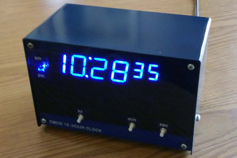
Figure 3. A CMOS 12 hour clock with a seconds display.
Technologies
As our discussion suggests, a clock of this kind may use any of the familiar integrated circuit technologies. TTL and its relatives in general require more current than CMOS, but both work perfectly well. If you want to really go back in time, there are RTL counters that can be used.
Driving Displays Directly
Usually, in circuits like these, each digit (except perhaps the hours 10s) is identified by a counter whose BCD output goes to a driver. The driver — for example, a 74LS47 or CD4511 — has seven outputs that the driver sets high or low so the seven segments of a display present the digit. The CD40110 is a decimal up/down counter that includes a driver; its seven outputs drive the segments of a common-cathode LED display directly. We can build a clock using CD40110s, but counts that stop short of 10 require additional logic that responds to the segment outputs.
For example, the minutes 10s counter must reset when its count reaches 6; a reset signal must respond to segments that appear together in the digit ‘6,’ but not in any lower-valued digit including ‘0.’ Similarly, to identify when to roll the hours count over from 13 to 1 (for a 12 hour clock) or from 24 to 00 (for a 24 hour clock), logic must respond to inputs to the two hours digits that uniquely identify 13 or 24, respectively.
Figure 4 presents a circuit for the minutes 10s digit using a CD40110. This counter must reset to 0 when its count reaches 6. The digit ‘6’ illuminates, among others, the e, f, and g segments of its display; these are not all on in any preceding digit. A three-input AND gate identifies this pattern and raises the reset line to the CD40110; the counter immediately resets to zero. (Alternately, a NOR gate could detect a unique pattern of low outputs from a CD40110.)
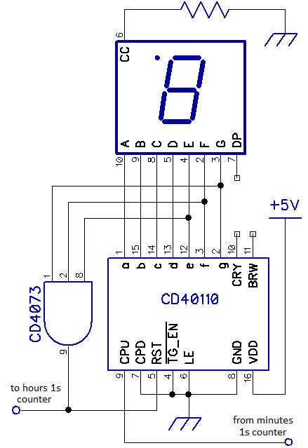
Figure 4. A circuit using a CD40110 counter/driver that counts from 0 through 5 and, upon detecting segment signals unique to ‘6’, resets to zero.
Negative BCD Displays
In 1969, Hewlett-Packard introduced the 5082-7000 display — the company’s first. It is not a seven-segment display. Each unit contains 28 red LEDs (dots) with which to form digits and circuitry to drive the diodes corresponding to the value represented by a negative (inverted) BCD input.
That is, in the four inputs that represent a digit, a high voltage (+5V) represents a 0 bit and a low voltage (0V) represents a 1 bit — the opposite of modern practice. One more LED is a decimal point.
Figure 5 shows the structure and pinout of the 5082-7000. These and similar displays can occasionally still be found.
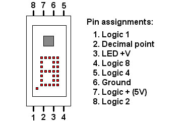
Figure 5. A diagram of the Hewlett-Packard 5082-7000 LED display.
One way to use displays like these in a counter-based digital clock is simply to invert each counter output; BCD outputs become the negative BCD inputs that the driver/displays expect. A more elegant and economical solution derives from this observation: Counting downward in positive BCD yields the same sequence of representations as does counting upward in negative BCD.
The appropriate choice here is a presettable binary counter that can count down, such as the CD4516 and the 74LS193. To count up from zero in negative BCD, set such a counter to 1111 — the inverted representation of zero — and count down. The outputs of the counter are then directly acceptable to displays like the 5082-7000. Figure 6 shows inside and outside views of a 24 hour clock that uses four of these displays.
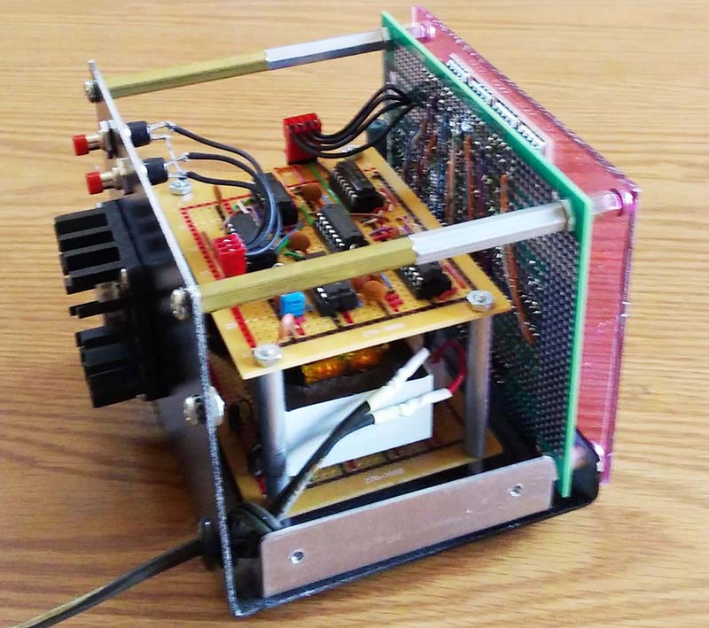
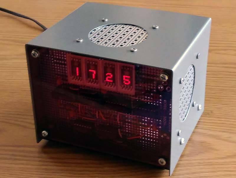
Figure 6. Inside and outside views of a clock that uses four HP 5082-7000 displays, whose inputs are negative BCD.
When counters are used in this way, the minutes 10s counter, for example, must be reset when its output reaches the inverted representation of 6. The minutes and hours 1s counters must be reset to 1111 when they reach the inverted representation of 10.
Similarly, the hours counters must be reset correctly at 13 or 24. Figure 7 presents a circuit appropriate to these digits; it sets its counter — a CD4516 — to 1111 when it detects the inverted representation of 10 (0101) and thus cycles through the inverted representations of 0 through 9.
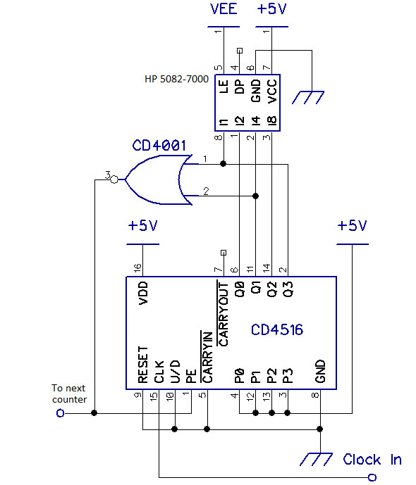
Figure 7. Counting from 0 through 9 in negative (inverted) BCD.
Switch Debouncing
Clocks of this kind are generally set in one of two ways. The first sets the minutes and hours individually using a signal of, say, 4 Hz or so. The second presents the clock’s counter chain with 60 Hz for fast setting or, again, 4 Hz or so for slow setting.
In either case, signals from the time base must be switched. Often, this is done directly with pushbutton switches. Unfortunately, many such switches bounce on both make and break, so setting becomes more random than predictable. Simple debouncers can use flip-flops or R/C circuits.
Switch debouncers can also use the ubiquitous NE555 or one of its relatives. The circuit in Figure 8, for example, appears in Timer, Op-Amp & Optoelectronic Circuits & Projects, by Forrest M. Mims III. The ‘555’s output is high until the switch is closed, when the output goes low. Should the switch itself bounce on make or break, the ‘555’s output still will not.
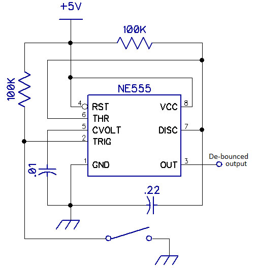
Figure 8. A switch debouncer using an NE555.
There are also integrated circuits designed specifically as switch debouncers. The best known is probably the MC14490, which contains six independent debouncing circuits. This IC is eminently simple to use, requiring just one external capacitor. Connect a switch to an input and use the corresponding output.
In all these cases, however, signals from the time base are not directly switched. A debouncing circuit renders a switch’s output clean, but that output is a high or low voltage which must then control the disposition of the signals. The 74LS125 and 74LS126 are described as “quad buss buffers,” and the CS4066 as a “quad bilateral switch.” Chips like these can implement switching at the control of a debouncer’s output.
These ICs all contain four independent SPST switches, each with a control line. In the 74LS125, for example, when the control line for a switch is low, its input is connected to its output. Otherwise, the output is in a high-impedance state.
Figure 9 shows a circuit in which two debouncers in an MC14490 and the four sections of a 74LS125 select one of three signals from the time base — 60 Hz for fast setting; 4 Hz for slow setting; or 1/minute for running — to be passed to a clock’s chain of counters.
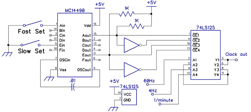
Figure 9. Selecting one of three inputs using a MC14490 switch debouncer.
Conclusion
These are a few of the many possible variations on the general theme of discrete logic digital clocks. If you have a few LED displays, counters, drivers, and simple logic, you can probably build a timepiece. Consult the datasheets of the ICs you choose to use, breadboard everything first, and have fun.
Finally, don’t forget to scatter several .1 µF bypass capacitors from the positive supply to ground in any clock. NV