You’re interested in astronomy and want to observe the same patch of sky for several nights in a row. After a night of observation, you ask, “Tomorrow night, when will that patch of sky be in the same position relative to me? What about the next night, and the night after that?”
Certainly, you can compute when — according to your watch — that feature of interest will be in the same place. Alternatively, you can keep track of astronomical or sidereal time: Time based not on the position of the sun in the sky, but time based on the distant “fixed” stars. By this sidereal measure, a distant star will always be in the same place at the same time.
As the sidebar explains, the sidereal second, minute, hour, and day are fractionally shorter than their standard counterparts. Sidereal clocks measure this time.
Sidereal Time
Pick a location on earth and note when the sun is directly overhead. The time until the sun is overhead defines the solar or standard day which we divide into 24 hours. Each hour is divided into 60 minutes and each of those into 60 seconds, of course.
Consider now the appearance of a distant star directly overhead. The time until that star is overhead again defines the sidereal or astronomical day, which is subdivided into hours, minutes, and seconds.
As Figure A illustrates, because the earth rotates around the sun and revolves on its axis, the sidereal day is about four minutes shorter than the standard day, and the same is true of the other units.
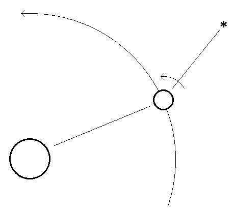
Figure A. Why the sidereal day is slightly shorter than the standard day.
More precisely, all the sidereal units are shorter than their standard counterparts by a factor of about 365.24/366.24. More precisely yet, one sidereal second = 0.997227707 of a standard second. Sidereal seconds, then, must average out to this fraction of the standard second.
A Sidereal Clock
At the end of last year, a fellow reader of N&V contacted me about a digital clock that counted and reported standard and sidereal time, both in 24-hour format. It needed some work, and he sent it to me.
He had owned the clock for at least 20 years, but it appeared to date from the 1980s. It contained both TTL and CMOS integrated circuits, including two MM5318Ns. These are 28-pin DIP ICs that carry out most of a clock’s computations. Many such types were produced at that time; they have since been superseded, of course, by microprocessors.
Physically, the clock was in good condition. Its wooden case was undamaged, and all its parts were present. It had a detachable line cord and a jack for an external source of 12 VDC. The standard side ran a little fast and the sidereal side matched the standard side, rather than counting sidereal time. Figure 1 shows the clock after its restoration.
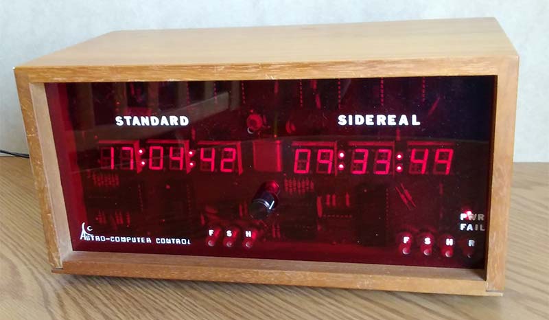
Figure 1. The IC-based standard and sidereal clock.
Unfortunately, we had no documentation for the clock at all. It was manufactured by a company called Astro-Computer Control of Port Matilda, PA, about which there is no information online, and we had nothing on paper. In particular, there was no circuit diagram, so we only had a general idea of what each part contributed to the clock’s operation.
Figure 2 shows a hand-drawn sketch of the major components on the clock’s circuit board.
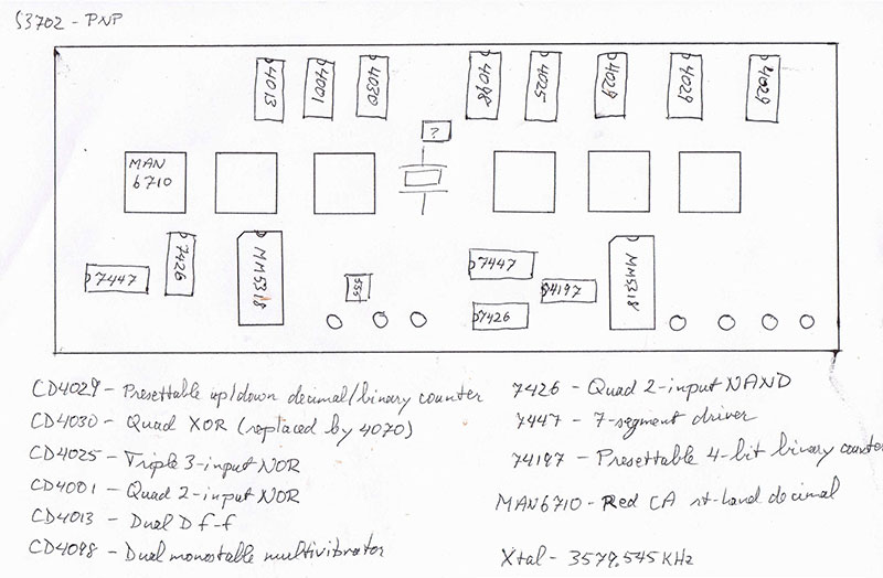
Figure 2. A sketch of the ICs and displays on the clock’s board. The small circles indicate pushbutton switches.
The markings on an eight-pin DIP were illegible, though it was identified soon enough.
The largest clue was the pair of MM5318Ns. These ICs were designed to place time information on a CRT TV screen in combination with another chip, the MM5841. An MM5318N generates seven-segment and negative (inverted) BCD outputs for hours, minutes, and seconds, and outputs to control six digits. The signals for the digits are multiplexed; when a digit output is low, that digit’s values are present on the chip’s BCD and seven-segment outputs. The left ‘5318 controls the standard clock and the right one the sidereal clock.
Several TTL ICs (including two 7447 seven-segment drivers) drive the clock’s LED displays. CMOS chips control each clock’s counting. On the clock’s back panel is a connector for a computer, which we ignored.
The MM5318N accepts either a 50 Hz or 60 Hz signal, as determined by a high or low voltage on its pin 14. The eight-pin chip was identified as an MM5369: a deceptively simple oscillator and divider. Its oscillator frequency is determined here by a 3579.545 kHz crystal. That signal is pulled up slightly and divided by 216 to yield the necessary 60 Hz.
Figure 3 shows the oscillator/divider circuit.
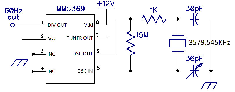
Figure 3. Generating a 60 Hz signal with an MM5369.
The trimmer capacitor determines the oscillator’s exact frequency. This is fine for the standard clock, but the sidereal side must run fractionally faster, and it’s a tiny fraction. There are various ways to count and report sidereal time with an MM5318N and the technology of the 1980s. Remember, no microprocessors.
Computing Sidereal Time
One technique inserts extra pulses in the 60 Hz signal to the clock chip so that the pulses average out to 0.997227707 as long as 60 Hz pulses. This can be closely approximated by adding four extra pulses for every 1,461 60 Hz pulses.
A second changes the chip’s counting mode from 60 Hz to 50 Hz, without changing the frequency of its input signal; just often enough and long enough to, on average, count sidereal time. In particular, every 2,922 pulses the counting mode is changed to 50 Hz for 40 pulses. (This technique was awarded patent number 4933920 in 1990.)
Another option is two entirely separate clocks — each with its own oscillator and adjusted individually — and a fourth begins with an oscillator frequency high enough that it can be divided down to both 60 Hz and the fractionally higher frequency.
Our clock contains one MM5369 and one 3579.545 kHz crystal. This eliminates the third and fourth options. The apparent date of the clock’s manufacture prohibits the second as well. The details of the insertion of extra pulses, however, remain unclear.
Operating on the Clock
The identical behavior of the two sides of the clock suggested a flaw in the counting circuitry associated with the sidereal side. Near the sidereal side’s big IC were several CD4029 presettable binary/BCD up/down counters. These were replaced one at a time, and after the last replacement, the sidereal side ran faster as it should. (It’s possible that the chip was not faulty, but poorly connected through corroded contacts.)
When the clock was powered by the AC line, the sidereal side now ran much faster than it should have, but with a 12 VDC source, its relationship to the standard side was correct. Looking at its input signal with an oscilloscope revealed two signals of slightly different frequencies. When they lined up, all was well, but as they fell out of phase, the sidereal side ran fast.
After 40 years, the few electrolytic capacitors couldn’t be counted on, so they were all replaced. Unfortunately, this didn’t resolve the problem. What I did was simply abandoning the AC line and powering the unit with a 12 VDC wall supply.
While the relationship between the two sides was now correct, the entire unit ran fast. The capacitors in the oscillator circuit of Figure 3 determine how much the crystal’s frequency is pulled. Replacing the non-variable capacitor with one of a slightly larger value allowed the trimmer to set the frequency correctly.
Figure 4 shows the clock’s main board in place after these changes.
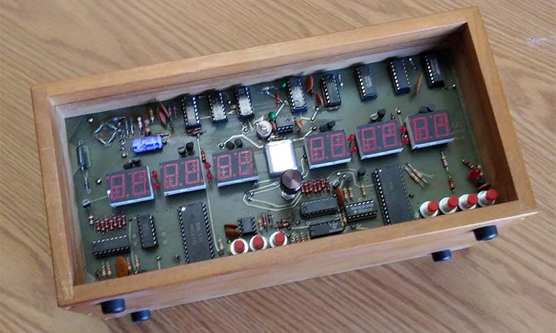
Figure 4. The clock’s main board. Note the trimmer capacitor near the crystal. The knob below the crystal controls the display’s brightness.
The pushbutton switches set the two sides.
Performance
With the changes, the relationship between the standard and sidereal sides of the clock was correct. All that remained was adjusting the trimmer capacitor to the left of the MM5369 to set the oscillator frequency. This took longer (in days) than the rest of the project.
The clock had to run at least overnight to evaluate its accuracy relative to an “atomic” clock. Eventually, however, both the standard and sidereal sides of the clock ran accurately to within a few seconds per day. Further fiddling with that trimmer could improve the clock’s accuracy, but the necessary adjustment will be tiny.
A Standard Clock Using an MM5318
Though the MM5318N was not designed to drive a stand-alone clock, the sidereal clock shows that it can do so; the chip generates all the necessary signals. Alone, these signals aren’t appropriate to drive a display, but they can drive chips that do. Here is such a clock, using a multiplexed common-anode display. Figure 5 shows most of its schematic.
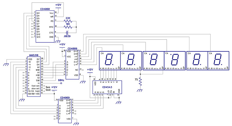
Figure 5. Most of an MM5318-based standard clock. See the text for a discussion of pins 13, 16, 17, 18, and 19.
The MM5318 counts input pulses to track time, of course, so the goal is to provide it with the necessary inputs and process its outputs to drive the display. The circuit in Figure 3 provides 60 Hz input to the ‘5318’s pin 19; alternatively, this signal could be developed by some other oscillator/divider circuit or derived from the line. The CD4060 is a lower frequency oscillator/divider; its three signals to the ‘5318 count in binary to select the multiplexed digits in turn.
Pins 16, 17, and 18 set the clock via SPST intermittent switches to ground: hold; slow set; and fast set, respectively. Normally-open pushbuttons are the obvious choice here as in the sidereal clock. Also, an SPDT switch that connects the ‘5318’s pin 13 to either +12V or ground determines whether it reports time in a 24 or 12 hour format.
Presentation of digits to the displays imitates the sidereal clock. Pins 2 through 5 of the ‘5318 carry inverted BCD representations of digits. The CD4069 hex inverter inverts these values and presents them to a CD4543 seven-segment driver which generates the corresponding segment signals and sends them to the display.
The display is multiplexed, and there are several ways this can be done. The matching segments of individual digits can be connected together, or multi-digit displays may already be so connected. The first option is used here, though the digit’s decimal points are not connected to each other. Rather, the DPs in the second and third digits (which form the colon) connect to ground through a low-value resistor.
The digit-select outputs of the ‘5318 (pins 20 through 25) are active low; the current digit’s line is near 0V while the others are high. To drive common anode displays, these values must be inverted. This is done by a CD4009 or CD4049. This clock was implemented on a RadioShack protoboard with the displays on another smaller board with the two connected by a right-angle header. A case bent up from sheet stock holds the setting and time-display switches and the power connector. Figure 6 shows the interior of the completed unit.
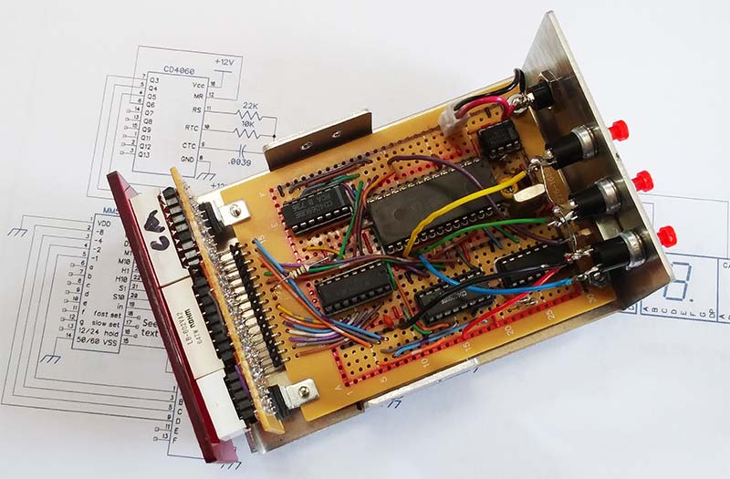
Figure 6. A standard clock based on the MM5318.
The circuit in Figure 5 can drive common cathode displays with the following changes. First, replace the CD4009 or CD4049 with a CD4050 — a non-inverting buffer. Second, connect pin 6 of the CD4543 driver to ground instead of the +12V; this reverses the polarity of the segment signals. (Alternately, use a CD4511.) How to handle the colon’s decimal points depends on the display.
A word of warning. My experience with the MM5318 suggests that this chip is electrically fragile. Be careful to avoid static charges near it and be cautious about connecting it.
Many clock ICs were designed and produced around the time of the MM5318. They offer fertile ground for experimenting and building. NV
Many thanks to Willis du Pont both for the project itself and for his cogent observations and suggestions during the clock’s repair and writeup.