Give your next project a modern look and feel with a touch screen display!
In the first article, we downloaded the Nextion IDE (integrated development environment), built a couple screens with various objects, and tested it in simulation. For this installment, we’ll be loading software onto a real Nextion TFT display and interacting with a PIC16F1824 microcontroller programmed with ME Labs PBP3 BASIC software. Finally, it will be tested on a breadboard.
Prerequisites
It is assumed you have already read the Touch Screen Display Part 1 article in Issue-4 of Nuts & Volts and have downloaded the Nextion IDE Editor software (see Resources). For the PIC side, if you don’t already have the PBP3 software, go to http://pbp3.com/download.html and grab your copy. (Note, only the PBP3 Gold is able to program the PIC16F1824. It’s available as a free 30 day trial if you wish to test it.) A PIC programmer will surely be needed. I strongly suggest you go to www.Microchip.com and download the PIC16F1824 datasheet for easy reference. Also, we’ll be using real hardware in this installment which requires a Nextion display, a breadboard, a PIC16F1824 processor, as well as a few ancillaries (resistors, LEDs, a pot, etc.).
This time, we’ll be frequently referencing the Nextion Instruction Set. Although it’s available in the IDE (so long as you’re connected to the Internet), I chose to print it out for easier reference (I’m one of those 50+ years old school types who favor paper). I have made numerous notes to my printed copy. Due to the length, the PBP code will not be printed in this article but is available in the downloads. As a side note, the PBP3 BASIC firmware’s fundamental function is to convert BASIC to ASM. The ASM created by PBP is not easily extracted and edited. Also, there’s no easy way to “port” code from PBP to C. It would have to be rewritten in C. There is a massive amount of information on the Internet supporting the Arduino platform for Nextion.
The Premise
The objective is to create an HMI (Human Machine Interface) using a Nextion TFT display that communicates with a PIC16F1824 processor to actually do stuff. To keep it short and simple, we want:
- A real LED that indicates the state of a binary/boolean button on the Nextion.
- An LED that will vary brightness based on an analog value from the Nextion using the PWM function in the PIC.
- A physical button connected to the PIC that will turn something on and off on the Nextion display.
- An analog reading on the Nextion display to reflect the value of a pot on the breadboard.
This gives us one digital and one analog variable (X2) going both ways. With these basic tools, you can build quite an impressive project; you can communicate and display digital and analog values both ways, changing them from either side as needed.
The PIC16F1824
I wanted a mid-grade PIC processor that wasn’t uber new, nor a dinosaur. The PIC16F1824 fits the bill. It has ADC, UART, and several other CIPs we won’t be using for this article. In other words, it’s capable and relatively modern. It has 14 pins (more than we need) but allows for adding more “tools” to your project later (or debugging).
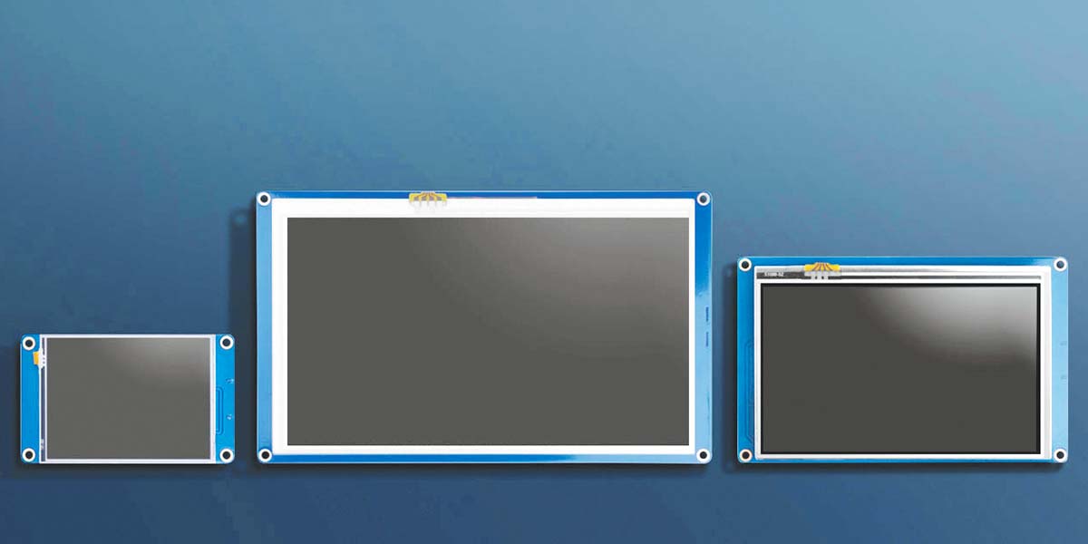
The Display
Keeping with the “cheap” concept while learning, this article will be built around the smallest NX3224T024_011 2.4” (240 x 320 pixel) resistive touch display. Nextion sells displays as large as 9.0” (800x480 pixels), for a total of eight size choices. If your project requires something larger than 2.4”, you have several options.
Instruction Set
In the previous article, the Nextion Instruction Set wasn’t much more than a mere footnote. For this phase, the Instruction Set will be referenced quite often. You may wish to print it for easier reference (and notes) as mentioned previously. At a minimum, be sure you have either the web version or the Instructions tab open in your Nextion IDE (which requires Internet access).
Schematic
We’ll be breadboarding a fairly simple circuit to facilitate digital and analog inputs and outputs from and to the PIC processor, feeding our Nextion display. When you look at the schematic in Figure 1, you’ll see lots of unused pins on the PIC. In fact, we could actually do this experiment with an eight-pin PIC. The extra pins are to add more buttons, switches, knobs, and other real world gizmos to your experiment later. You could also substitute the PIC16F1824 with practically any other PIC of your choosing.
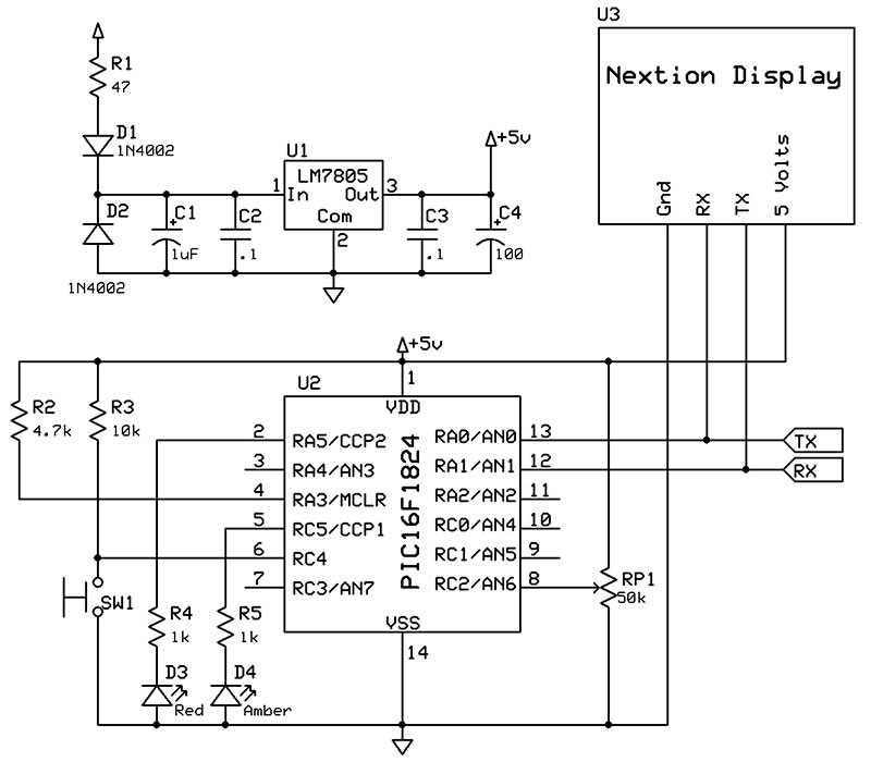
FIGURE 1. Schematic for the PIC/Nextion project.
According to the PIC datasheet, RA0 is the EUSART TX pin, and RA1 is the RX pin. These can also be assigned to RC4 and RC5, respectively, with the APFCON0 register. UART communication protocol requires the RX from one device to be connected to the TX on the other, and vice versa.
The PIC RA0 (TX) is connected to the RX pin on the Nextion, and the PIC RA1 (RX) is connected to the Nextion TX pin. We’ll throw a momentary button on RC4 because it’s digital only. It will use a pull-up resistor R3, making it Active-Low (when pressed, it’s at ground state; = 0). A pot on RC2/AN6 gives us an analog value to send to the Nextion. RA3 is the !MCLR, or RESET pin. It should be tied to five volts with a 4.7K ohm resistor.
The power supply is a standard LM7805 with diode protection and capacitor filters. This allows you to use a nine volt battery or a 12 volt bench power supply and still get the requisite five volts for the circuit.
Figure 2 shows the breadboard loaded as per the schematic. There are a few extra caps that aren’t in the schematic for extra filtering, and I omitted the diodes (I have confidence in my bench power supply). I’m using 1K resistors to limit current to the LEDs. You may want to use smaller values to make them brighter.
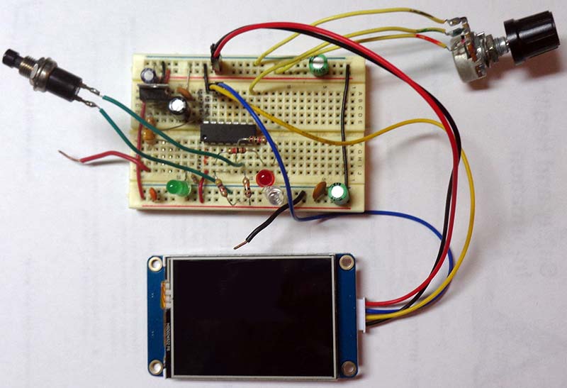
FIGURE 2. Breadboard for the PIC/Nextion project.
The Nextion
Since we covered how to add objects and set their Attributes in the first article, that process will be abbreviated here. If something doesn’t make sense, please review Part 1.
We’ll be using the same NX3224T024_11 2.4” (240x320 pixels) resistive touch screen as in the first article. The display is oriented at 90° horizontal. We’ll also be reusing the Splash1 screen (available in the downloads), as well as the MS_Sans_16 and WideLatin_48 fonts.
To configure the screen, we’ll be using objects from the Toolbox:
- Picture (p0): pic = 0 (Splash1), x = 0, y = 0, w = 320, h = 240
- Text (t0): bco = 34800, pco = 63488, font = 1 (WideLatin_48), txt = NUTS, txt_maxl = 4, x = 20, y = 0, w = 120, h = 40
- Text (t1): bco = 34800, pco = 65504, font = 0 (MS_Sans_16), txt = AND, txt_maxl = 3, x = 140, y = 10, w = 60, h = 30
- Text (t2): bco = 34800, pco = 63488, font = 1, txt = VOLTS, txt_maxl = 5, x = 200, y = 0, w = 120, h = 40
- Number (n0): bco = 65535, pco = 0, font = 1, val = 0, lenth = 3, x = 220, y = 50, w = 100, h = 40
- Button (b0): bco = 65504, bco2 = 1024, pco/pco2 = 0, font = 1, txt = Blink LED, txt_maxl = 9, x = 35, y = 145, w = 250, h = 40
- Slider (h0): mode = horizontal, bco = 1024, pco = 63488 (defaults), wid = 25, hig = 40, val = 0, maxval = 255, minval = 0, x = 0, y = 200, w = 320, h = 40
- Variable (va0): Just leave default settings.
For this new project, I added another PNG picture (NV_A2_LEDr in the downloads) which is nothing more than a 60x60 pixel red circle with Noise and Lens Flare filters. This will have to be added to the Picture library the same way we added Splash1. From the Picture window, click on the “+” and add it from the appropriate file folder. From the Toolbox, add a new Picture (p1). Then, in the Attributes pane, change:
- Picture (p1): pic = 1, x = 130, y = 45, w & h = 60
Nextion Code
Let’s start with the page load event. From the Attributes drop-down, select page0(Page). In the Events window, in the Preinitialize E... event, add the following code:
vis p1,0 //p0 is not visible
n0.val=0 //Clear n0
h0.val=0 //Clear h0
Click on the yellow button b0 in the display area. In the Touch Press Event (12) tab of the Event window, enter the following code:
prints 0x06,1 //Sends Cmd Code to PIC
if(va0.val==0) //Previously Off
{
va0.val=1 //Now On
}else
{
va0.val=0 //Either way, Toggle
}
prints va0.val,1 //Send State
prints 0xFF,1 //Terminate Sequence
prints 0xFF,1
prints 0xFF,1
Next, click on the Slider (h0) at the bottom of the display area. In the Event window, you have three tab choices. The rightmost tab, Touch Move(5), is the one we’ll enter the following code into:
prints 0x07,1 //Sends Cmd Code to PIC
prints h0.val,1
prints 0xFF,1 //Terminate Sequence
prints 0xFF,1
prints 0xFF,1
At this time, open the Nextion Instruction Set to review a few things pertaining to the above code. The “prints” command (Section 3 - Operational Commands) instructs the Nextion to send data over the serial port.
In the Instructions, there are three print (Send UART) options. The “prints” version allows us to send any number of bytes we want. The “,1” at the end of each line sends one byte. The print command follows a format that will add unnecessary filler bytes that require additional code at the PIC end to unravel.
The first obvious anomaly is the use of prints 0xFF,1 three times to terminate a UART transmission. The very first thing the Instructions mention is “All instructions over serial: are terminated with three bytes of 0xFF...”. We could send anything we wanted over serial, and the Nextion will obediently send it. However, for consistency, we’ll use the Nextion convention. When we decipher the PIC code, it will make more sense.
Notice we created a Number object (n0) but nowhere in the Nextion code did we provide any means of doing anything with it. Also, we added a Picture of a red bulb (p1), then turned it off at start-up. Again, nothing further is mentioned in the Nextion code. Changes are handled from the PIC side of things.
PIC16F1824
PBP3 BASIC is a rich, high-level language quite capable of doing virtually anything on an eight-bit PIC. The complete program (NV_A2.pbp) is in the downloads. If you are following the bouncing ball with an older pre-v3.0 of PBP, you’ll have to change the extension from .pbp to .bas.
You’ll see that we are doing a few things “the hard way” instead of using convenient PBP commands. Open the program. Starting at the top are the DEFINEs where we declare the Oscillator at 4 MHz, and include (commented out) declarations for UART, the ADC, and an Interrupt Handler (ISR, not commented out), Tog. The line DEFINE INTHAND Tog will allow us to handle the UART Receive interrupts in an Assembly (ASM) Language Interrupt.
Next is the Configurations which include every configurable option, denoting its value. If not explicitly stated, one could assume a default value on start-up, which may not always be the case. It’s better to spell everything out. Tog is listed right after GOTO Init (more on Tog later).
Right after Init: are the PORT Aliases. I like to define every PORT pin, even if it isn’t used. Next are the Special Function Registers for the Oscillator, PORTs, UART, ADC, CCP2 (PWM), Timer 2 (used for CCP2), and Interrupts. The APFCON0_1 Registers were needed to place RX, TX, and CCP2 on their correct pins.
Lastly are the Variables. A couple notes: The variable Hin is listed as Hin VAR BYTE[10]. The bracketed 10 reserves 10 memory addresses — all called Hin — but with offsets. In short, this creates an array to store bytes of received information from the Nextion. It’s a bit large for this project, but perhaps too small for others.
Also note nRx and Work add SYSTEM to the description. Since our Interrupt Handler will be written in ASM, SYSTEM allows us to refer to these variables by their names without a prepending underscore (nRx instead of _nRx). Lastly, we first declare Work as a BYTE and SYSTEM. Notice how we alias individual bits of Work with a unique name. In PBP, if you declared Dat VAR BIT, the compiler would assign a memory address for that single bit. Declaring a Byte, then declaring each bit, you could do Work = 0 and clear each bit in one fell swoop. Furthermore, the ASM syntax doesn’t like BCF Dat but does like BCF Work, 0.
Finally, we get to the code. The first line is PAUSE 200. When the Nextion first starts, it shoots out 0x00, 0x00, 0x00, 0xFF, 0xFF, 0xFF, (Startup), then 0x88, 0xFF, 0xFF, 0xFF (Ready). We can skip all that and start communications when both sides are ready. The rest of Start turns off the amber LED (Aled = 0), clears a few working variables, fires up Timer 2, enables UART Receive (RCSTA.4 = 1), and enables Interrupts (INTCON.7 = 1).
Skip over Main for now and let’s look at the subroutines. Sort loads the Hin array as Bytes are received from the Nextion. When three $FFs are received, it sets our Mail flag indicating Transmission is Complete. (Dealt with in Main.)
Next, Clear_Hin rotates through the array, Hin clearing each memory address. The reason for this is we need to count 0xFF ($FF) Bytes to know when the Nextion is finished transmitting. As a value could conceivably be 0xFF, it shouldn’t be counted as End of Transmission. Clearing Hin avoids left-over values that could potentially contaminate future Receive transmissions.
Filter is where we decipher the Nextion packet. Looking at the Nextion Instruction Set, Section 7 - Format of Nextion Return Data, it lists Code Bytes and their meaning. The subroutine Filter is where we decipher them. As you scroll down through the SELECT CASE offerings, you can match every Code from Nextion to a CASE, plus three extra.
Referencing the Nextion Instruction Set for a moment, notice the Codes are sequentially listed. However, there are several gaps; 0x06 > 0x10, 0x13 > 0x19, 0x21 > 0x22, 0x25 > 0x64, 0x72 > 0x85, 0x8A > 0xFC, and 0xFF. Consider these pockets as empty apartments to house your variables (except 0xFF covered shortly). This gives us a total of 215 available slots to assign variables.
Back to Filter in the PBP code, CASE $06 is where the state of our Nextion b0 Button arrives, and CASE $07 is for our Slider (h0) value. Additional variables would be assigned other available hex values. CASE $FF is special, as there is no Nextion command 0xFF. Receiving $FF for Hin[0] indicates we received a real value of $FF for h0 (or something else) and mistook it for the first $FF in the End of Transmission sequence. Bytes are shifted one address to the left, and the Filter routine is exited (to preserve our Mail and rDone flags).
Get_Knob first reads the ADC value of our pot and decides if it changed (IF Knob != OldKnob THEN). If it has, we send the new value to the Nextion (GOSUB Send_Knob). Send_Knob sends ASCII “n0.val=“ and our ADC value for Knob. We’re using a variable Kval to determine how many ASCII characters we need to send. IF Knob > 100, THEN we send three digits (Kval = 2). If it’s less than 100, we send two (Kval = 1), and if it’s less than 10, we only send one character (Kval = 0). FOR b0 = 0 TO Kval sends only the needed characters. Without this special clause, a value of 99 would read 990 on our Nextion n0. A value of 7 would read 700.
Back to the top to Interrupt Handler Tog. You can insert ASM programming into PBP3 one of two ways: Prepend your ASM command with an “@“ at the leftmost of the margin, then add a space or tab before the ASM command (@ NOP).
The other method is to place ASM in the leftmost of the margin before your ASM code and ENDASM at the end, both of which are used.
The Memory regions of all PIC processors are separated into BANKs. The Program Counter (PC) will go to the specified Register Address, but only the last part of that Address (most commands). If the Bank Select Register (BSR) is on a different BANK than the one you want, the PC is sent to the wrong address. The ASM command BANKSEL is shorthand to get the BSR to the proper BANK to access the Register you need.
PIR1 is the Register where we find the RCIF, or UART Receive Interrupt Flag. The actual flag is bit 5; or PIR1.5. In ASM, it’s PIR1, 5. BCF is an ASM command to clear the bit to 0 (Bit Clear F, where “F” is an Address). MOVF allows us to place the value of RCREG into the Working Register, W. We then place that value into our variable nRx with the MOVWF command.
Finally, we need to set two flags: rDone and Dat. Since they are bits of our variable Work, they are set with BSF (Bit Set F) Work, and either ,1 for rDone or ,0 for Dat. Finally, the RETFIE command restores our Registers (Automatic Context Saving; another reason for choosing the PIC16F1824 over older offerings) and returns the PC to the line of code where we were Interrupted.
Interrupts and PBP3.1
The Assembly Interrupt we’re using is one of three popular methods of handling Interrupts, and the least popular of the three. Assembly language is the native language for any microprocessor. Theoretically, it requires the least amount of memory space, and the fewest Instruction Cycles to execute.
The PBP manual does cover Assembly Interrupts in the Advanced section starting at 6.3 on page 252. PBP3 has ON INTERRUPT GOTO... where the PBP compiler handles everything for you. You then code in the familiar PBP language.
The third option is the DT_INTS developed by the late Daryl Taylor. It requires two Include files, but offers much more flexibility over On Interrupt GOTO, and is easier to program than ASM; essentially, the best of both worlds. I was privileged to contribute to a digital book on the subject, which can be found at http://dt.picbasic.co.uk. (The PBP3 manual does not cover DT_INTS.)
If you only need the UART Receive Interrupt for your project, the code listed is cut and paste functional. If you require Timer or other Interrupts, you may want to change to something more familiar.
Sending Values to the Nextion
The subroutine Send_Knob requires a bit of explanation. The Nextion Instruction Set tells us that all transmissions are in ASCII. It also tells us that most Nextion commands can be sent via UART.
We’ll be using the PBP LOOKUP command to bit-bang out our Nextion commands. PBP offers a simpler solution than the route chosen. You could use HSEROUT or even DEBUG to send data. Nevertheless, follow along as we manually execute our transmissions.
The LOOKUP command sends ASCII “n0.val=“ to get things started. The ARRAYWRITE command allows us to convert up to three digits of Knob to ASCII; using array KnobA[3]. A quirk with ARRAYWRITE is when you have a numeric value that is greater than 100, you get the expected value, as there are three digits to convert to ASCII. No problem. If there are fewer than three digits, the end result is not what you’d expect.
The value 99 becomes 990. The value 7 becomes 700. Just below ARRAYWRITE KnobA... is an IF/ELSEIF statement that limits how many digits will be sent to the Nextion. Finally, there’s a FOR/NEXT LOOP that sends three $FFs. Note that in the C programming language (and the Nextion Instruction Set), hexadecimal is denoted as 0xFF, while PBP uses the $FF nomenclature.
The subroutine Send_Button is very similar to Send_Knob, except we test our Sw input and send an ASCII command that reflects the state of our button. IF Sw = 0 THEN indicates the button is pressed (pulled high with R3, grounded when pressed). We then send “vis p1,1” to the Nextion — a literal command turning on our red circle. If the Sw button is not pressed, “vis p1,0” is sent, turning off the circle.
Back to “Main”
Scroll back up to the Main routine. The first task is to check to see if our Sw button has changed states. If so, we tell the Nextion with GOSUB Send_Button. Next, we read the pot value, but only once per 256 cycles through Main (using Rot). Within the Get_Knob routine, we check to see if Knob changed since the last reading. If it did, Send_Knob is called.
The third section of Main checks for Framing or Over-run Errors and does a UART RESET if there are any. Fourth, if the Nextion has sent us anything, we have to load it into our Hin array. When we get our End of Transmission (3 x $FF), we know we have a complete packet and it’s time to “read our mail:” IF Mail = 1 THEN : GOSUB Filter. Every pass through Main increments our Rot variable. When it rolls over from 255 to 0, we check our Knob value again. This throttles visits to the ADC Register and reduces congestion for our slow 9600 baud UART.
Uploading Our Software
The software for the PIC is created in the MicroCode Studio IDE with PBP3.1. Programming a PIC chip is really dependent on the programmer you use. The PICkit3 has its process, while the ME Labs U2 programmer (my personal favorite) uses a different process. I leave it up to you to know how to program a PIC chip with the programmer you have.
The software for the Nextion is created using the Nextion IDE. Programming is done one of two ways: serial port or SD card. Instructions for using a serial port are quite explicit and covered numerous times in various Nextion documents. However, using the SD card to program was quite difficult to find. For this reason, I’ll cover that method here.
The SD card slot in most laptops is sized for the regular SD card. The Nextion takes only microSD cards. The solution is something like Figure 3. All Electronics offers SD card adapters for micro-to-standard. The SD card must be formatted as MS-DOS FAT 32.
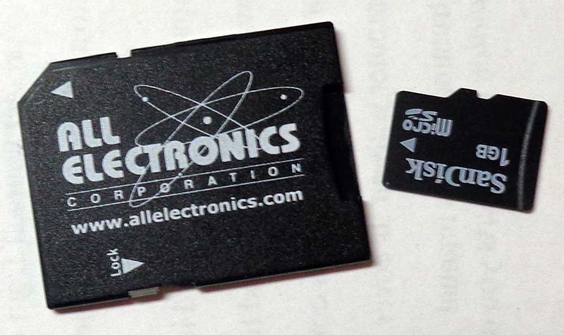
FIGURE 3. Micro-standard SD card adapter.
Make sure the SD card is completely empty with no folders. From the Nextion Editor, click on File, then “Open build folder.” A new window will appear with your project(s) listed and the .TFT file(s). Copy the appropriate .TFT file to the SD card. When you create a program in Nextion, it generates an .HMI file, which is the whole project. The .TFT file is the only thing the Nextion can use for programming.
Copy the .TFT file to the SD card, remove the micro from the holder, insert it into the Nextion, then power it up. You’ll see it loading, running through the programming sequence, then finally it will read, “Update Successed!” (remember, Nextion is a Chinese company). Power-down, remove the SD card, and you’re done!
The Grand Finale
With your breadboard loaded as per the schematic, the PIC programmed with the software in the downloads, and the Nextion programmed with the screen we just created, you should have a functioning HMI. If you turn the knob on the breadboard, the Nextion n0 value should read the ADC value (0 >> 255). Press the momentary button and the red circle appears; let off and it disappears.
From the Nextion screen, press “Blink LED” and the amber LED lights up. Press it again and the LED goes out. Slide the red bar across the Slider (h0) and the red LED gets brighter and brighter. Slide it the other way and the red LED gets dimmer (see Figure 4).
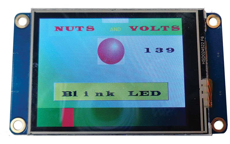
FIGURE 4. Actively talking to a PIC.
You can now add gizmos and transmit digital and analog data back and forth. You have the basic building blocks for a most amazing modern creation! NV
Parts List
| Description |
Value |
Digi-Key PN |
| R1 |
47 ohms 1/2 watt |
S47HCT-ND |
| R2 |
4.7K ohms 1/4 watt |
CF14JT4K70CT-ND |
| R3 |
10K ohms 1/4 watt |
CF14JT10K0CT-ND |
| R4 |
1K ohms 1/4 watt |
CF14JT1K00CT-ND |
| R5 |
1K ohms 1/4 watt |
CF14JT1K00CT-ND |
| RP1 |
50K Pot |
987-1733-ND |
| D1 |
1N4002 |
1N4002-TPMSCT-ND |
| D2 |
1N4002 |
1N4002-TPMSCT-ND |
| D3 |
Red LED |
160-1127-ND |
| D4 |
Amber LED |
C566C-AFF-CU0W0252CT-ND |
| SW1 |
NO MOM Button |
EG2031-ND |
| C1 |
1 µF Elec Cap |
493-10461-1-ND |
| C2 |
.1 µF Disc Cap |
BC1160CT-ND |
| C3 |
.1 µF Disc Cap |
BC1160CT-ND |
| C4 |
100 µF Elec Cap |
P5182-ND |
| U1 |
LM7805 |
296-47192-ND |
| U2 |
PIC16F1824 |
PIC16F1824-I/P-ND |
| U3 |
NX3224T024_011 |
N/A |
Resources
Nextion Main Website
https://nextion.tech/
Nextion Editor Software Download
https://nextion.tech/nextion-editor/
Nextion Instruction Set Download
https://nextion.tech/instruction-set/
ME Labs PBP3
http://pbp3.com/download.html
Microchip
www.Microchip.com
Digi-Key
www.DigiKey.com
All Electronics
www.AllElectronics.com
Downloads
What’s in the zip?
Source Code
Parts List
Images
HMI File