Give Your Nextion a Look of Class!
Back in Part 1 of this series, we designed a simple Nextion display screen and got it to do stuff. However, the look was rather droll. In this installment, we’ll make it sizzle.
New IDE
Since writing Parts 1 and 2, Nextion has updated their Integrated Development Environment (IDE, Version 0.59 as of this writing), Instruction Set, and Editor Guide. I suggest reviewing the first two installments and the new Editor Guide to refresh your memory on basic commands, as this article makes assumptions. Anything new in the v0.59 IDE will be covered as applicable.
Nextion’s website is https://nextion.tech, where you can download the latest IDE, Instruction Set, and Editor Guide (and purchase products). The Editor Guide covers installing the IDE, configuring a new project, and using the Toolbox items.
I need to thank the Nextion North American Distributor, Patrick Martin again for his invaluable help in crafting the code for this article. He spent considerable time working with me to give you the best information possible.
Build Something Useful
While this article qualifies as “Nextion Part 3,” it also qualifies as “Build a Small Engine Ignition Timing Controller, Part 1.” Small engines have a fixed ignition timing, as the magneto is solidly bolted to the engine. Of course, a simple controller could change ignition timing by turning a knob, but it would still only meet Best Mean Timing (BMT) within a narrow window of engine operation (which is what happens stock, and why we need this controller!).
Besides, advanced timing could cause engine damage at higher loads and RPM. A timing table allows changes in timing as engine parameters change (like a car). While peak power is about the same, the “area under the curve” increase is truly amazing! To program the table while testing (driving) requires a Human-Machine Interface (HMI). Enter the Nextion.
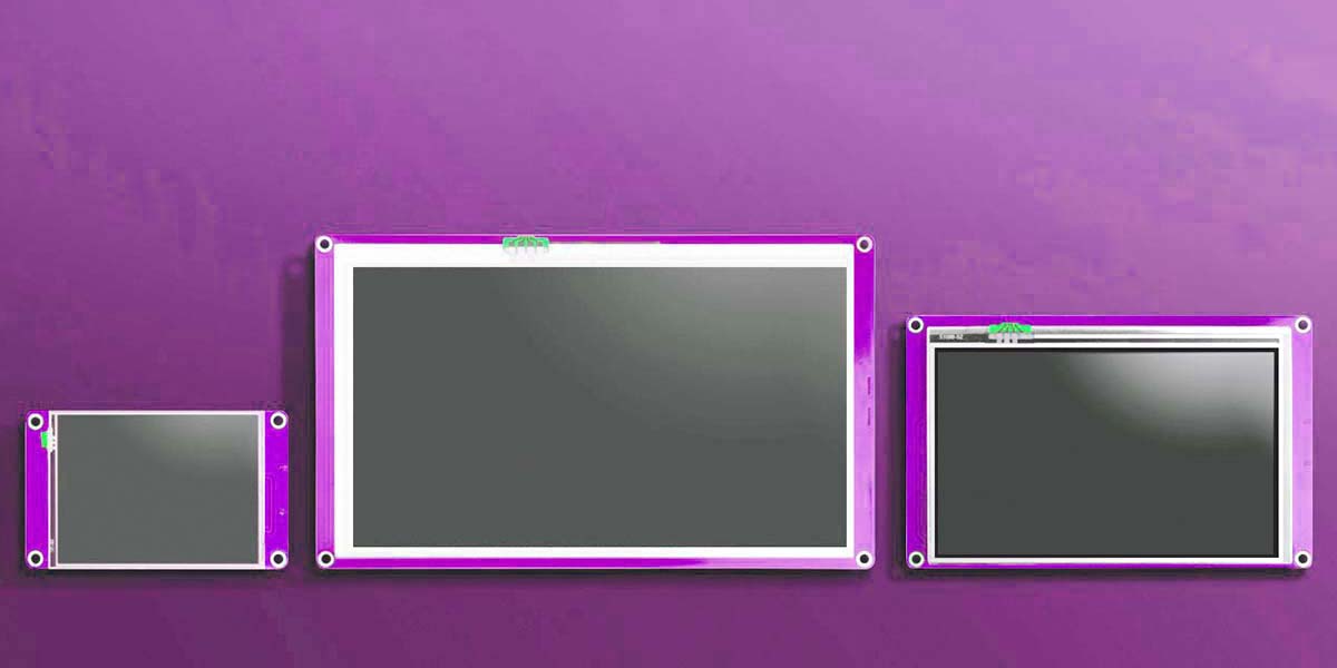
We’ll use the Nextion 3.5” Basic display. The 2.4” used previously is too small for this project. The 3.5” has 320x480 pixels which is large enough to fit table cells and other controls.
In Part 5, we’ll cover tach signal input, reading vacuum for load, and other hardware. The finished controller uses the Nextion display as a programming and tuning tool, including many features found in professional products. To wrap up the series, we’ll install it on my son’s Manco two-seater and do some basic tuning.
What to Display?
At a minimum, we need engine RPM. It can be a digital number box or an analog gauge. We also need table cells (numbers) to tweak timing for best performance within a small window. For the MAP sensor, we’ll use a vacuum number/gauge. RPM gets the X axis of our timing table, while the MAP signal takes the Y axis. A display (number) for current ignition timing lets us know where we are at any given time, plus we’ll highlight the current cell within the displayed table.
We need one screen for tuning with our X-Y table and critical inputs, and another just to monitor what’s happening (large, easy-to-read gauges). A data logging screen helps with the tuning process. Another to adjust brightness and put it to sleep takes advantage of the power-saving Nextion features.
Getting Started
One of our goals is to create “sexy” images to act as buttons and overlays. We can make much better-looking buttons than the IDE provides. To create attractive objects requires software such as Photoshop. There are several comparable programs; feel free to use what you like.
It goes without saying, you need the Nextion IDE (free download). For now, we’ll work with Debug in Simulation Mode, but to build the project, you’ll need an actual display.
After installing the IDE, create New, give the project a name, and save it to a folder of your choice. Next, select Basic from the top. Choose the NX4832T035_011 3.5” model. Then, in the top left side bar, click Display and choose 90 Horizontal. When you click OK, you get the IDE with a clean slate.
Modern displays use a start-up screen with an image (usually a company logo), listing the version and date created. Let’s make a personalized start screen for our project. You need a picture; your go-kart, mini-bike, logo, or something meaningful.
Open your image in Photoshop. Crop it to 100 dpi and 480x320 pixels. You may need to play with the cropping to reduce distortion. Photoshop allows you to select a crop size and center it where you want. Reduce the opacity to no more than 50%. Save this image as a BMP/16-bit color, as it will be the backdrop for our individual pages (Figure 1).
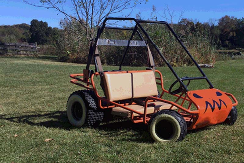
FIGURE 1. Backdrop image.
Next, add your start screen text to the picture (name, version, copyright, etc.). Flatten the image and save it as a BMP format with a new name. In the bottom left corner of your Nextion IDE, select the Picture tab. Click on the large red “+” and add both your new backdrop and start screen images to your project. From the Attribute pane: sta=image, pic=1 (your start screen). Mine features my son’s go-kart (Figure 2). In the Attribute pane, click on “sta” and select image. Next click on pic, browse, and select your start screen (Figure 2).

FIGURE 2. Start screen.
From the Page pane (top right of the screen), click on the left-most icon (folder with a green “+”) and add a new Page. A new blank screen will appear (page1). Click on page0 in the Page pane to display our start screen again.
From the Toolbox, add a Timer (tm0). In the tm0 Attribute pane, change “tim” from 400 to 2000. This will display the start screen for two seconds (2,000 milliseconds). With tm0 selected, in the Event pane (bottom right of center), you will only have one option: Timer Event(1). Type in dp=1 (Display Page 1). Click on Save, Compile, then Debug. Your start screen should appear for two seconds then go blank, as it will switch to page1.
Building Our Tools
With the “fun” start screen built, we can move on to other tools. From the Page pane (top right), click on page1. You’ll see a blank screen. In the Attribute pane, click on “sta” and select image. Next, click on pic, browse, and select your backdrop image (Figure 1).
FONTS
Part 1 was written using an older IDE. The new v0.59 can create much nicer looking fonts by aliasing them. In the bottom left pane, click on the Fonts tab (it reads Pictures now). From the top header, click on Tools, then Font Generator. In the pop-up screen, put Height=16. Make sure the “Anti-aliasing of fonts” box is checked.
In the Font drop-down, select Arial (or another font of your choice). Make sure Bold is unchecked. In the bottom right Font Name box, type Arial_16, then click Generate font. It will ask you to give it a name (again, Arial_16).
Save it to the project folder and add it to the project when prompted. Repeat the process for an Arial_32 (Height=32) and an Arial_48_Bold (you must check the Bold box). These fonts should appear in the bottom left Fonts pane.
BUTTONS
Before building new screens, we need some attractive tools. Let’s go back to Photoshop and create a generic button.
Start a new project, 100 dpi, 75 pixels wide x 30 pixels high, RGB color. With the Paint Bucket tool, fill the area with some light color. (I chose an aqua blue.) Next, with the Rounded Rectangle tool, choose a similar but darker color and create an inset. I set Zoom to 300% and aligned top right to bottom left corners with the tool cross-hairs to get an inset darker color. At this point, most of the rectangle is filled with the darker color.
With the same Rounded Rectangle tool, choose the outer-most color (or something complimentary) and add a smaller inset. You should now have a thin dark band around the perimeter. This is our generic button; see Figure 3. Flatten the image and save to the project folder as a 16-bit BMP, then add it to the project.

FIGURE 3. Generic button.
Nextion allows you to use pictures as backdrops for Buttons. From the Toolbox, add a button and put it somewhere on page1. In Attribute, click on “sta” and select image. Click on pic and select this generic button; repeat for pic2. It will choose font=0 by default (Arial_16).
Change txt from newtxt to Start. Change pco2 to red. In the Touch Release Event tab of the Event pane, type dp=0. Click Save, Compile, then Debug.
The start screen appears for two seconds then jumps to page1. Click the button and hold it. The text “Start” changes from black to red. Release and it takes you back to the start screen (for two seconds). We now can create modern looking “buttons” and other objects. Delete the test button.
GAUGES
In Part 1, we explored the Gauge tool. Although an indicator would sweep 360 degrees, it looked “kindergarten-ish.” We need handsome gauge faces to dress up our tachometer and vacuum gauges. You can create your own gauge face from scratch (see the article downloads) or start with a photo.
I’m madly in love with the ’68 Plymouth Barracuda gauges. They had a large speedo on the left, a large four-gauge cluster on the right, and a smaller option pod in the center. Options included a tach, clock, and “Performance Indicator” (vacuum gauge). I created a tachometer and vacuum gauge using pictures of the Barracuda tach and Performance Indicator.
Ideally, select a gauge with zero at the 9 o’clock position, sweeping clockwise. It makes software calculations easier. The Barracuda gauges start somewhere else, and you’ll see the added calculations required as we write the code.
Start with a picture of the gauge. In this case, there are two different faces: one for the tach and one for the vacuum. I isolated the bezel in Photoshop, sized it to 100 dpi/220x220 pixels, and saved it by itself. Next, I isolated the center button (100 dpi/60x60 pixels) and saved it by itself. Refer to Figure 4.

FIGURE 4. Gauge center button.
Next, size and overlay the tachometer face on the bezel by selecting it with the Elliptical Marquis Tool, Copy, Paste, then position it. If there are any blemishes, touch them up; see Figure 5.
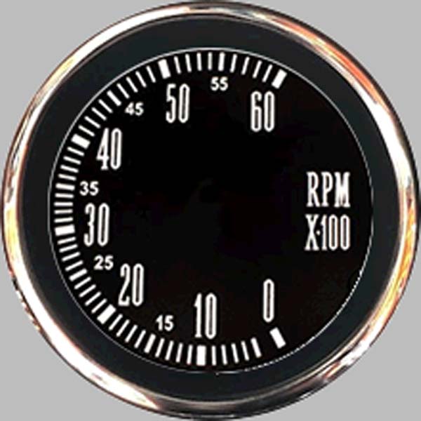
FIGURE 5. Blank tachometer.
Repeat the process for the vacuum gauge as shown in Figure 6. Flatten and save both images.
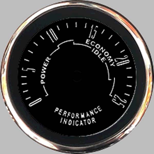
FIGURE 6. Blank vacuum gauge.
In Photoshop, open your generic backdrop image (Figure 1). Click on your Elliptical Marquis Tool and select your tachometer face and Copy. Click on your backdrop and Paste. Move it to the top left corner. Repeat for the vacuum gauge face placing it top right; see Figure 7. Flatten this image and save it with a new name as a 16-bit BMP, then add it to the Nextion project.
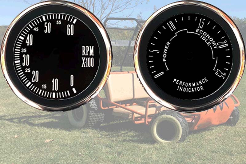
FIGURE 7. Both gauges overlaid on our backdrop.
Add another Page to your project (page2). (We’ll create a Menu Page with page1 later.) Set sta=Image and pic=[your gauge cluster]. Lastly, if your gauges use a center button, add it to your Picture pane as well.
From the Toolbox, add a gauge (z0). Set sta=crop image and picc=[your gauge cluster]. Size your gauge (z0) so the needle stays within the face of the gauge once centered. For mine, z0: X and Y = 23; W and H = 174. The default color (pco) for the needle is a drab green. Change it to red (63488) with wid=3 (thickness of the needle).
Unless the zero on your gauge falls at exactly 9 o’clock, it will point to the wrong place. Play with the z0.val value until it points to zero. Mine zeroed out at z0.val=242.
Add a second gauge (z1) and repeat the process for the vacuum gauge: W and H = 174; X = 283; and Y = 23. Set sta=crop image and picc=[cluster]. Again, play with z1.val (in the Attribute pane) until the needle points to zero; mine was z1.val=326.
If you have a center button on your gauges, grab a Picture (p0) from the Toolbox, size it the same as your button image (60x60), select it under pic, then manually place it in the center of your tachometer. You can work the math, but depending on minute angle differences in your original picture, it may look better slightly off mathematical center. My buttons were X = 80, Y=77 for the tach (p0); and X = 339, Y = 77 for the vacuum gauge (p1) (refer to Figure 8).
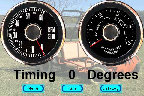
FIGURE 8. Finished gauges page with gauge objects, center buttons, timing info, and page change buttons.
To experiment, add a timer from the Toolbox (tm0). Change tim in the Attribute pane to 50 (ms). In the Event pane, type:
z0.val+=1
z1.val+=1
Click Save, Compile, then Debug to watch what happens. The Debug screen has an Instruction Input Area in the bottom left. Type dp=2 and Enter to get to the Gauges screen. When the needles will move one click, our center buttons disappear. The needles will move to the 9 o’clock position and stop. Let’s add a few lines to refine it:
z0.val+=1
if(z0.val==360)
{
z0.val=0
}
vis p0,1
z1.val+=1
if(z1.val==360)
{
z1.val=0
}
vis p1,1
Click Save, Compile, and Debug to see what effect that has. (Don’t forget dp=2.) Now, the center button stays visible (vis p0,1...). The needles will continue to loop around in a full circle as long as you let them. We’ll need the z0.val when the needle points to zero on our gauge face, what RPM and vacuum is represented when zX.val=0, and a few key markers throughout the working range. Delete the code in the tm0 Event pane as it was just a learning exercise.
From the Toolbox, add seven variables. Leave va0 and va1 alone, but change va2 to rpm, va3 to vac, va4 to tim, va5 to OldRpm, and va6 to OldVac in Attribute. The naming makes things easier for the PIC code (covered in Part 6).
Add a Text and give it the following Attribute: sta=crop image; font=2 (Arial_48_Bold); picc=[gauges]; txt=Timing; txt_maxl=6; X=36; Y=224; W=160; and H=50. Add another Text with the same Attribute values: txt=Degrees,;txt_maxl=7; X=291; and W=170. Last, add a Number: sta=crop image; picc=[gauges]; Arial_48_Bold; X=203; Y=224; W=75; and H=50.
To establish markers, click on z0 and adjust val until your needle points to 1000 RPM. Write that number down. Do the same for 2000, up to about 5000 RPM. Find how large the average gap is for a 1000 RPM difference. Calculate 1000 / that number to find how many RPM per degree (.val) change in the gauge needle; mine is 27 RPM.
In the tm0 Event pane, type:
if(rpm.val!=OldRpm.val) //Reduces Flicker on Actual Nextion
{
OldRpm.val=rpm.val //Update OldRpm
if(rpm.val==0) //Engine Off
{
z0.val=242 //Your Gauge Face Zero
}else
{
va0.val=rpm.val/27 //Step size
if(va0.val<118) //242 + 118 = 360
{
z0.val=va0.val+242 //Zone Between Gauge Zero and z0.val=0
}else
z0.val=va0.val-118 //Zone Above z0.val=0
}
}
}
vis p0,1 //Turn the center button back on
Click Save, Compile, and Debug (+ dp=2). Next, try different RPM values like rpm.val=1000 (in the Instruction pane). If we got it right, the needle should be pointing to the right spot. Try higher and lower values to check accuracy. You may have to adjust your math a bit to get the needle lining up properly.
My vacuum gauge reads inches of vacuum. Zero = atmosphere (about 100 kPa) and 14.7” = ~ 50 kPa. The PIC software calculates kPa, so some scaling is in order. If your gauge reads kPa, it will be easier.
For my gauge, z0.val=0 puts the needle at 4” of vacuum, and z0.val=326 points the needle to zero. At 50 kPa (14.7” vacuum), z0.val=107. With these numbers, I calculated the following:
if(vac.val!=OldVac.val) //Reduces Flicker
{
OldVac.val=vac.val
if(vac.val>86) //> z0.val=0, 86 kPa
{
va1.val=vac.val-86 //Variable #1 Value -= 86 kPa
va1.val*=24 //<4” (>86 kPa) Scaling Value = 2.4
va1.val/=10 //(* 24 / 10) Yields (* 2.4)
z1.val=360-va1.val //Range Below z0.val=0
}else if(vac.val<86) //<z0.val=0, 86 kPa
{
va1.val=87-vac.val //Vacuum - 87 kPa Offset
va1.val*=29 //>4” (<86 kPa) Scaling Value = 2.9
va1.val/=10 //(* 29 / 10) -> (* 2.9)
z1.val=va1.val //Load Value to Gauge
}else
{
z1.val=0 //Exactly 4” Vacuum (86 kPa)
}
}
vis p1,1 //Show Center Button
In the first section, we need z1.val = (vac.val - 86) * 2.4. The Basic Nextion cannot perform floating point math (* 2.4), nor can it perform multiple math functions in a single command line, which is why we multiply by 24 then divide by 10.
Also note that my constant in the first part was 2.4 and 2.9 in the second. Our tach reading used the same constant whether z0.val>0 or z0.val<0. The vacuum gauge couldn’t give a decent reading without the different constants. You may need to get creative with yours as well.
Click Save, Compile, Debug, and type dp=2 into the Instruction pane. Try vac.val=50 and see where the needle points. It should be 50 kPa or 14.7” vacuum; vac.val=100 should point to zero (or 100 kPa). Other values should show reasonable results.
Before we move on, add a Button (b0) from the Toolbox. In the Attribute pane: sta=image; font=0; pic and pic2=[your button image]; pco2=red; txt=Menu; txt_maxl=4; X=73; Y=280; W=75; and H=30. Add another button (b1) similar to the first button with the following changes: txt=Tune and X=203. Add one more button (b2) with the following changes: txt=DataLog; txt_maxl=7; and X=332.Click on the Menu button (b0) and in the Event pane, Touch Release Event(0) tab type dp=1. Click on the Tune button (b1) and in the Touch Release Event(0) type:
sys0=39 //Send Table Command
sys1=1
dp=3
For the DataLog button (b2) Event pane, type dp=5. These buttons will take us to the pages we want. Click on the background to select page1. In the Postinitialization tab of the Events pane, add:
prints 38,1 //Command Code for Screen Update Rate
prints 10,1 //Value 10 X 10 ms = 100 ms (10X / Second)
prints 37,1 //Command Code for Send Rotation
prints 1,1 //1 = On
This sends UART commands to the PIC to rotate RPM, Vac, and Tim transmissions. Next, in the Page pane, click on the Add icon until you have six pages loaded (page0 >> page5). Click on all the new pages and add your backdrop image (sta; Figure 1).
SLIDERS
One of the Nextion pages (Settings) will allow us to take advantage of the brightness control and screen saver features. A slick way of adjusting screen brightness is with a slider. In Photoshop, create a new project: 100 dpi; 480 pixels wide; and 60 pixels high. Click on the Gradient tool (right-click Paint Bucket) and select a fairly dark color (I chose a blue). Start at the left and sweep right the entire length of your picture and release. You should get a fade effect with dark blue at the left and white at the right. Save it as a 16-bit BMP. Close it and create a new project: 100 dpi; 30 pixels wide; and 60 pixels high. With the Paint Bucket, choose an extremely dark color; perhaps even black. Fill the whole project.
Next, select the Rectangle tool and lighten your color a bit. Place a rectangle inside your project with a small margin on all sides so that you have a “face” that adds the perception of depth. Next, select the Line tool, two or three pixels wide, and color it white (or a very light shade of your main color). Draw a vertical line down the center of your rectangle. It should look like a slider knob. Flatten the layer and save it as a 16-bit BMP. In the Nextion IDE Picture pane, add both to your project.
In the Page pane, click on page4 (it should already have your background image). From the Toolbox, add a slider (h0). At the bottom of the Attribute pane, W=480 and H=60. Close to the top, change both sta and psta to image. This allows us to plug our images into the slider.
Below psta, make wid=30 and hig=60; the dimensions of the slider knob. Leave max=100, but change min=20. This prevents screen blackout (good luck finding the knob if you do). Click on pic, browse, then select your slider image. Below that, click on pic2, browse, and select your knob image. Now, doesn’t that look much better?!?
Add a second slider (h1; same settings), placing it at Y=126. In Attribute, min=0, max=420. This slider will allow us to control the screen saver feature. With a value of zero, it never times out. Any value >0 will turn the screen off after that number of seconds; 420 = seven minutes.
Next, add a Number (n0) from the Toolbox. Set sta=crop image and select your backdrop. Use your Arial_48_Bold font. Place it at X=360, Y=196, and size it to W=100 H=50.
One at a time, add two new Texts from the Toolbox. For the first one (t0): X=60; Y=50; W=380; H=50; font=Arial_48_Bold; txt_maxl=17; txt=Screen Brightness; and sta=crop image, with picc=[generic backdrop]. For the second (t1): X=10; Y=196; W=340; H=50; txt_maxl=14; and txt=Screen Timeout, with the rest of the settings the same as t0.
Add two variables from the Toolbox: va0 and va1. In the Event pane under the Preinitialize tab, add the following code:
va0.val=dims
h0.val=dims
va1.val=thsp
h1.val=thsp
n0.val=thsp
Click on the top slider (h0) and in the Event pane, Touch Move(0) tab, type:
dim=h0.val
va0.val=h0.val
This adjusts the screen brightness to the slider value. Default is 100, full brightness. Using the dim=h0.val command allows you to see the results before committing to non-volatile memory.
Next, click on the bottom slider (h1) and in the Event pane, Touch Move(0) tab, type:
va1.val=h1.val
n0.val=h1.val
This will be your no-touch screen saver, in number of seconds. The Number (n0) will display your sleep slider value numerically. We are storing in temporary Variables (va0 & va1), as writing to the non-volatile memory has a limited number of writes. Click on the backdrop (page4), and in the Events pane, Page Exit tab (you may have to click on the drop-down to see it), type:
dims=va0.val
thsp=va1.val
if(va1.val>0)
{
thup=1
}
The difference between dim and dims is dim only applies until shutdown (volatile), while dims will be the new default setting (EEPROM). When thsp=0, the screen stays on. When thsp>0, it will turn the screen off after thsp seconds of no touch activity. Wake on Touch is controlled by the thup command, where thup=1 is enabled. Without a timeout, it is not needed.
When finished, we need a way out. From the Toolbox, add a button: X=203; Y=270; W=75; H=30; sta=image; txt_maxl=4; txt=Menu; pco2=red; font=0 (Arial_16); and pic and pic2=[generic button]. In the Touch Release tab of the Event pane, add dp=1.
When you click on the Menu button, it will take you to the Menu screen (coming soon). The screen looks like Figure 9. Click Save, Compile, Debug, then type dp=4 in the Instructions. Slide the two sliders and see what happens.
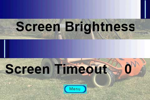
FIGURE 9. Settings page with fancy sliders.
To finish up the easy stuff, click on page1. We need four buttons from the Toolbox. Like you did for the Menu button on page4, set up your buttons with your button image. Position them so that they are evenly spaced on the screen. Label the first button (b0) Gauges, (b1) Tune, and (b2) DataLog, and label b3 “Settings” (Figure 10).
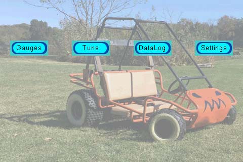
FIGURE 10. Menu page.
Click on Gauges (b0) and in the Touch Release tab of the Event pane, type dp=2. For Tune (b1), type:
sys0=39
sys1=1
dp=3
For DataLog (b2), dp=5, and for Settings (b3), dp=4. Click Save, Compile, and Debug. When the Menu page comes up, click on Settings. It should take you to page4. From there, click on Menu and it should take you back to page1.
A quick note: sys0=39 and sys1=1 are for RPM, Vac, and Tim updates, covered next time.
Conclusion
In this installment, we created a classy start screen, designed attractive buttons, sliders, Text boxes, and gauge faces, and got many of them working. Next time, we’ll build our Tuning screen, and Data Logging screen using the Waveform tool.
The finished Nextion software will be included in the Part 4 downloads. However, I did toss lots of goodies for this article into this part’s downloads. NV
Downloads
What’s in the zip?
Nextion Editor Guide
Nextion Instruction Set
Fonts
Graphics for Buttons