Add Ignition Timing Control to Your Go-Kart!
Previously, we discovered how easy it is to add objects to the Nextion display, dress them up, and communicate with a PIC MCU. In this installment, we build the Small Engine Ignition Timing Controller and Programmer hardware.
If you ask any speed shop dyno operator where the most power gains are to be had, overwhelmingly the #1 answer will be “ignition timing.” However, small single cylinder engines use a fixed magneto with a fixed timing setting. For the sake of emissions and durability, this setting will invariably be the most “retarded” setting throughout the load range. This means anything below Wide Open Throttle (WOT) and max RPM, the engine is not performing up to potential. By enabling ignition timing advance targeting Best Mean Timing (BMT), you improve torque and horsepower curves, plus Brake Specific Fuel Consumption (BSFC, or fuel economy). Your small engine will come alive with newfound power and economy!
Overview
Typical small engines are not designed to maximize power output nor engine life. Simply put, they are designed to be manufactured as inexpensively as possible, lasting a fairly reasonable amount of time (I was told 700 hours by a Tecumseh engineer). The engine used in this article is a Harbor Freight Predator 212 cc 6.5 HP engine featured on sale for $99 (at the time). My son’s go-kart was bought used with a non-running 5 HP Robin engine (and had a host of other issues). The 6.5 HP engine is spunky with only the driver, but add a passenger and you feel the extra weight. Small engines use a magneto triggered by a magnet in the flywheel. The magneto has a high-energy wire that connects to the spark plug and a small (20 AWG typically) wire that connects to the kill switch. Grounding the small wire shorts out the magneto, thus killing the spark. With no spark, the engine dies.
This “kill wire” outputs a scaled-down version of the spark output; around 16 volts peak on ours. This makes a suitable trigger signal. The negative pulse occurs at about six degrees Before Top-Dead-Center (BTDC).We can’t adjust ignition timing with a fixed magneto, so adjustability requires an automotive ignition coil, firing when we want spark. The coil and controller both require electricity to operate. Thus, a small lawn and garden (or motorcycle) battery will be required. A charging system would be nice but is beyond the scope of this article. For now, periodic battery charges will keep us mobile.
Inputs
All processing decisions are based on two hardware inputs:
Filtered Tach Signal
You can see the small wire signal in Figure 1. There is a negative 16 volt spike sandwiched between two positive spikes. It could be possible to filter this signal with a diode and opto-isolator, but you then have two signals per TDC. Charles Leo (ME Labs) told me about the MAXIM MAX9924 VR (Variable Reluctance) Signal Conditioner about three years ago that’s ideal for such a task. Unfortunately, it’s only available in a 10-pin MSOP surface-mount package.
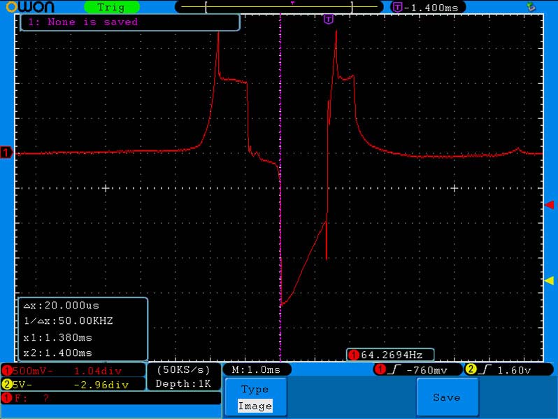
FIGURE 1. Raw tach input.
The top trace in Figure 2 is a positive signal filter (like an opto-isolator), while the bottom trace is the output from the MAX9924.
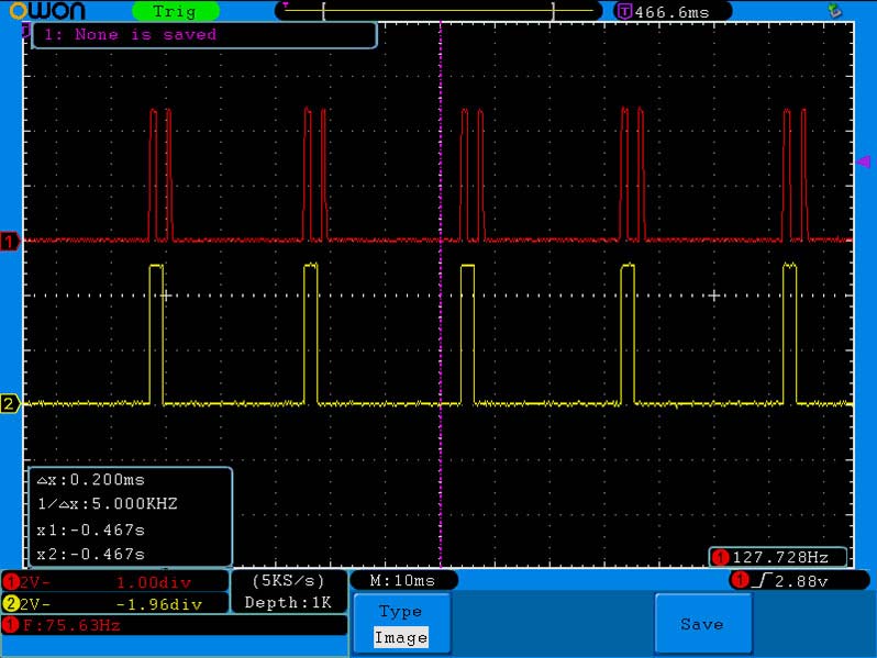
FIGURE 2. Opto-isolator top, MAX9924 bottom.
Clearly the MAX VR chip gives us a much cleaner signal to work with. The schematic for the MAX9924 is shown in Figure 3. (The flag “P 7” indicates that pin is connected to pin 7 of the PIC.)
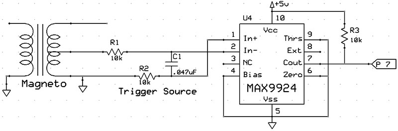
FIGURE 3. MAX9924 schematic.
“MAP” Sensor
To have an X-Y table, we need a load input; X = RPM and Y = Load. For automobiles, a Throttle Position Sensor (TPS) is a universal load sensor. In addition, cars add a Manifold Absolute Pressure sensor (MAP, for vacuum) and/or Mass-Airflow (MAF) sensor. It’s no small machining operation to add a TPS sensor to a small engine. MAFs have major challenges as well. However, if you can find a spot between the throttle plate and intake valve to drill a 3/32” (about 2.4 mm) hole, you can easily add a MAP sensor. Analog Devices makes an MPXA6115A pressure transducer with 15 to 115 kPa range, yielding a linear analog 0.5 to 4.5 volt signal. The port accepts a 3/32” hose. Although surface-mount, it has fat widely-spaced pins making it a breeze to solder. Figure 4 is the schematic.
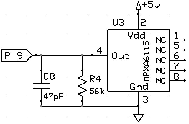
FIGURE 4. MPXA6115A MAP sensor schematic.
Outputs
The only output is the ignition coil driver. Whereas there are probably dozens of MOSFETs and transistors capable of driving an ignition coil, the International Rectifier IRGB14C40L IGBT is specifically designed for this task; the schematic is shown in Figure 5.
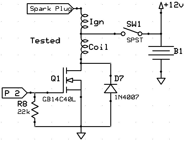
FIGURE 5. Coil driver schematic.
Everything Else
Power Supply
The PIC can operate anywhere from 2.5 to 5.5 volts. However, the MAX9924 and MPXA6115A both require a five volt supply. An LM7805 is a cheap and effective way to regulate five volts up to 1.5 amps. The 10 ohm/one watt resistor (R6) buffers the input, while diodes D4 and D5 prevent damage if power supply wires are reversed. Add a couple filter caps and we’re good; see Figure 6. (D4 and D5 can be 1N4007s.)
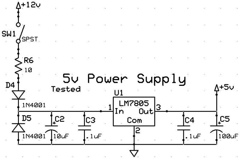
FIGURE 6. Power supply schematic.
PIC Processor
Microchip releases new PICs with more features (at a lower cost) practically every year. One of the latest releases is the PIC16F18426. It sports seven timers (we need six), Peripheral Pin Select (PPS), a range of oscillator options (particularly, we need MFINTOSC and 32 MHz HFINTOSC), many of the popular communications protocols (we need UART), a 256 byte EEPROM (to store our table), advanced ADC2 features (we just need eight-bit basic ADC for the vacuum), and many other peripherals we don’t need.
A huge thanks goes out to Charles Leo of ME Labs for adding the PIC16F18426 in a special PBP3 update ... JUST FOR YOU!! Plus, he reviewed Parts 5 and 6 to ensure you get the best plan of action possible. Pinouts are outlined in Figure 7. The In-Circuit-Serial-Programming (ICSP) pins were reserved for that function.
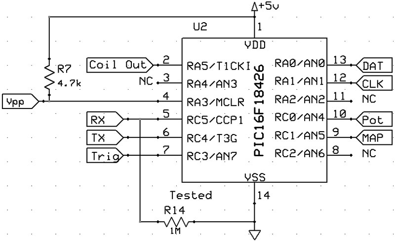
FIGURE 7. PIC schematic.
Nextion Programmer
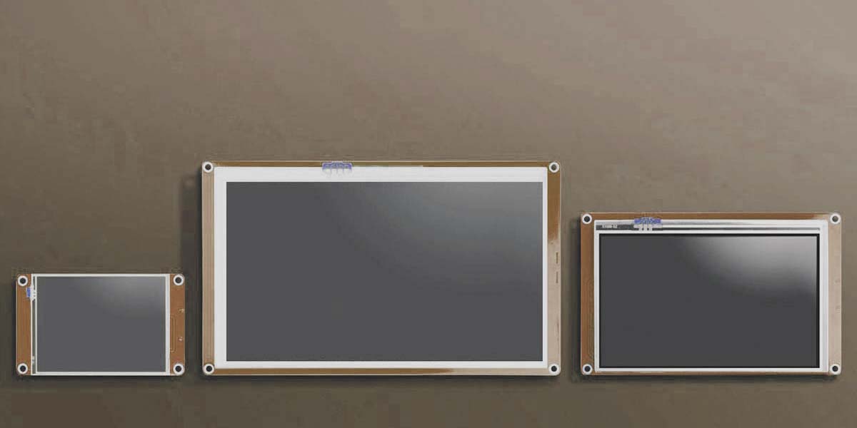
Having a glass touch screen display flopping around in a go-kart qualifies as a “hold my beer” move. We need to mount it safely in its own enclosure. Hammond’s 1553DTBUBKBAT is just the right size for the 3.5” Nextion, plus the battery compartment could allow use of a nine volt battery. (As this project is already complex, I chose to omit the additional Printed Circuit Board [PCB] and circuitry for the battery option.) You can opt for one of several colors; blue being my choice for this project.
The Molex connector (J1) and Nextion connector (J2) are represented in Figure 8. Remember, Nextion UART TX connects to the PIC RX and vice versa.
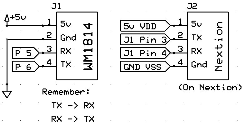
FIGURE 8. Programmer connector schematic; J1 is on the PCB, J2 is on the Nextion.
The PCB
A generic perf board might work if it weren’t for the two SMT devices (pressure transducer and VR conditioner). ExpressPCB made the board for this project. I’ve used them for about a decade. I order 10-15 new designs per year, and have NEVER received a bad board. If there was an error on the board, there was a matching error in the file I submitted. They have worked with me on special requests, and their deliveries are always on time (even expedited orders).
Having shopped around, their service and prices are competitive with the best of the alternatives. Plus, they’re “Made in the USA!” (Washington state).
Until recently, you had the option of Standard or Production quality. In low volume, the price difference is staggering (one unit: $76.08 standard vs. $257.80 production). However, they’ve added a third option: Proto Plus ($93 for one of what we’re using for this project), which looks pretty much like the production board, but at a price only slightly higher than the standard boards.
Proto Plus is a discount service for 1-10 boards with a size no larger than 21 square inches. Production is for orders one to 5,000 up to 12 x 14 inches. This made the two-layer Proto Plus board the cost-effective higher quality choice (Figure 9). It fits nicely in the Hammond 1455C802 enclosure. The .pcb file is in the downloads. ExpressPCB offers many other options, including multi-layer boards.
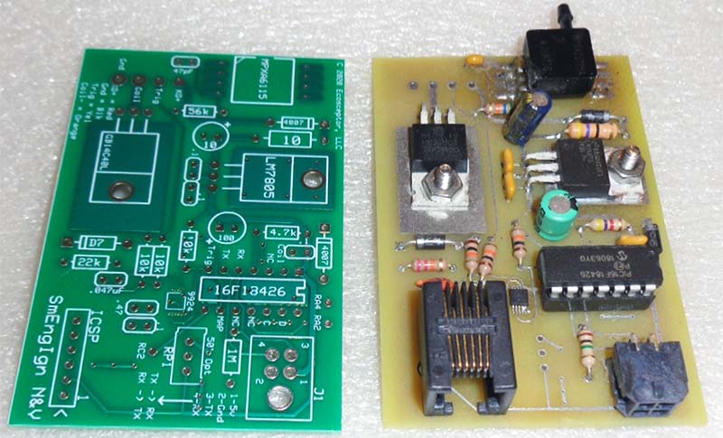
FIGURE 9. Proto Plus on left, standard on right.
Go to www.expresspcb.com and download their free software. They offer “Classic” and “Plus.” If you’re new to PCB design, the Classic is simpler and more intuitive. If you have PCB experience, you’ll find the Plus has more flexibility and control (with a steeper learning curve). Kudos to ExpressPCB for offering both. This project was created using Classic.
Fancy Wrapper
The enclosure is as important as any other component, as it protects the sensitive electronics in a rather harsh environment. The Hammond 1455C802 is a rugged extruded aluminum enclosure with optional mounting brackets, available in several colors. It’s not sealed, so it isn’t waterproof (Figure 10). Silicon sealer remedies that shortcoming. It also has slots for our PCB to slide into.
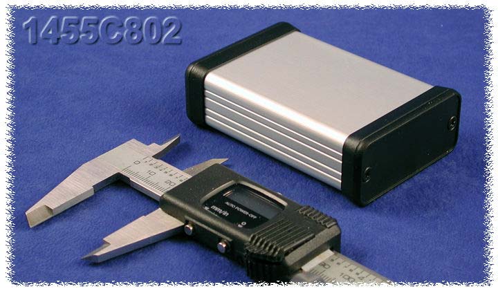
FIGURE 10. Hammond 1455C802 enclosure (photo courtesy of Hammond Manufacturing).
Other Incidentals
Since we won’t be permanently attaching the Nextion programmer to the controller, we need a connector to disconnect it when not in use. The PCB interfaces with the real world with wires. A fancy connector for power and coil wires would add cost, but for this project, wouldn’t really add functionality. Soldering those wires directly to the board suffices. However, a connector makes disconnecting the Nextion possible. A toggle switch disconnects power from the coil and controller, preserving the battery (refer back to Figures 5 and 6). Plus, with no power, no spark. It becomes your new kill switch.
Additionally, eyelets/spades should be used for the coil terminals, master switch, magneto kill switch wire (which can be disconnected from the factory kill switch), and battery connections. I prefer to use bare terminals and heat shrink over the crimp.
The battery negative should be connected to the engine block and chassis. The controller gets its ground from the connection at the engine block. Battery positive is wired to the master toggle switch. From the switch, two wires split to the coil+ and controller B+ input. Part 7 of this series will cover mounting these items.
The Circuit
I like to solder SMT parts first, as that allows me to use clamps to hold them in place while I finish. However, the transducer is big and lives at the edge, so it got soldered close to last.
Starting with the MAX9924, carefully solder it to the board. I smear a light coat of soldering flux on the pads with a pocket screw driver to help solder flow (Figure 11), then use a spring clamp to hold it (and dissipate heat) while I solder it (Figure 12). I’ll thoroughly clean and tin the smallest soldering iron tip I have so it’s sanitary.
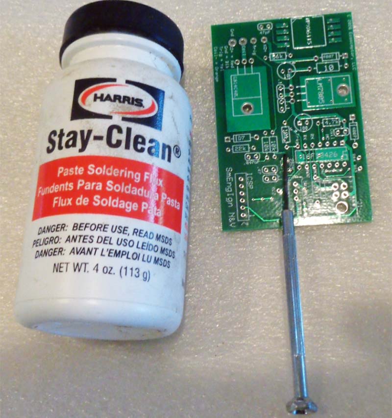
FIGURE 11. Prepping to solder the SMT MAX9924.
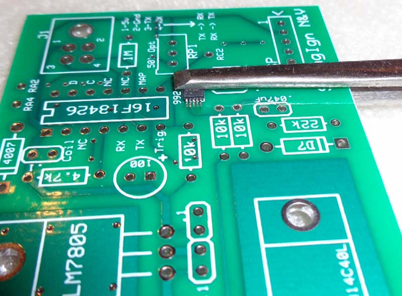
FIGURE 12. Clamp the SMT device to the PCB.
Next, I dab just a tiny blob of solder on the tip. Touch one of the corner pins of the SMT component, hold it for no more than a 1/2 second, then solder it to the PCB. The tiny dab of solder is good for 4-10 pins.
After soldering one of the pins, remove the spring clamp and inspect the alignment of the rest. Adjust as necessary, reinstall the clamp, then solder one bank of pins. Be sure to check (with a magnifying glass?) for “jumpers” of solder between pins. Flip the board around and solder the other bank.
Next, all the resistors get placed (Figure 13).
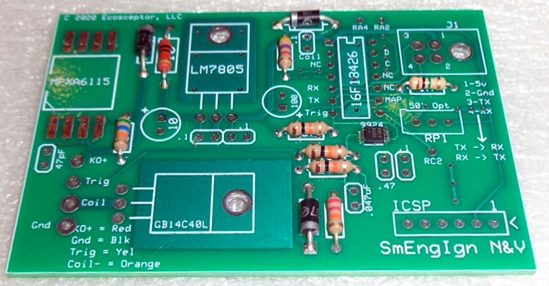
FIGURE 13. Short components soldered to the board.
From there, keep going with taller and taller parts, so they don’t fall out when you flip the board to solder. Both the LM7805 and IRGB14C40L are held to the board with #40 screws and nuts. Both get thermal compound, but the IRGB14C40L gets an additional heatsink. Be sure to put thermal compound between the IGBT and heatsink, and between the heatsink and the PCB (Figure 14).
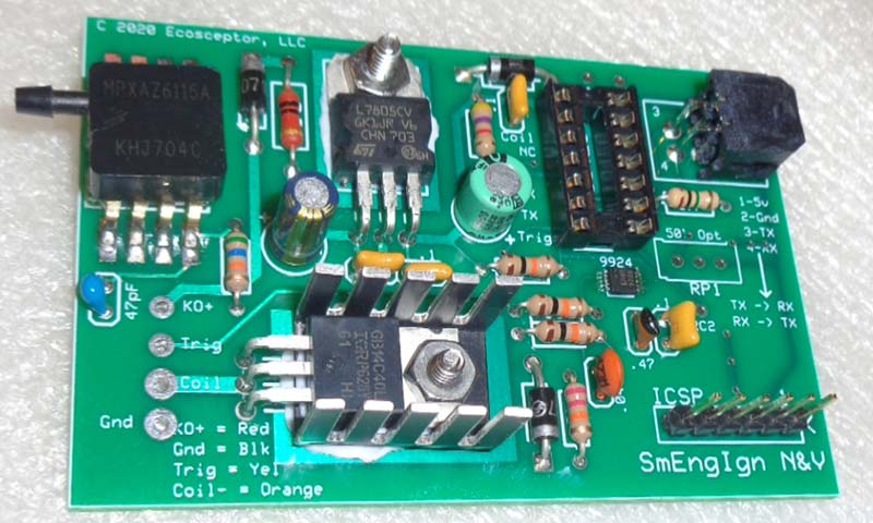
FIGURE 14. Everything but the wires soldered in place.
Note there’s a place for a board mount pot (RP1). It’s not populated for the article, but is an option if you just want to adjust timing by a fixed amount. (You would have to customize the software for that feature.) The schematic covers the essentials. None of the resistors are precision; 5%-10% versions will work well. Note that in the datasheet for the MPXA6115, the pull-down resistor is 51K ohms (at pin 4). I used 56K (R4 on the schematic) with no problems, as it’s a more common value.
Due to the electrically noisy environment, automotive grade components are recommended where possible. Also, 1N4001 diodes are shown for the power supply. Since we’re already using 1N4007 for the IGBT flyback, they can be used for the power supply as well.
Before installing the PIC, test the power supply. You should have a clean five volts (with >6.5 volts input). You can program the PIC with a PICKit 3 or 4 (or other Microchip option, see Figure 15), or the ME Labs U2 ZIF programmer (Figure 16).
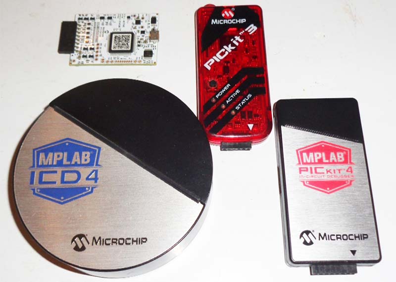
FIGURE 15. Clockwise: Snap, PICKit3, PICKIT4, and ICD4 programmers from Microchip.
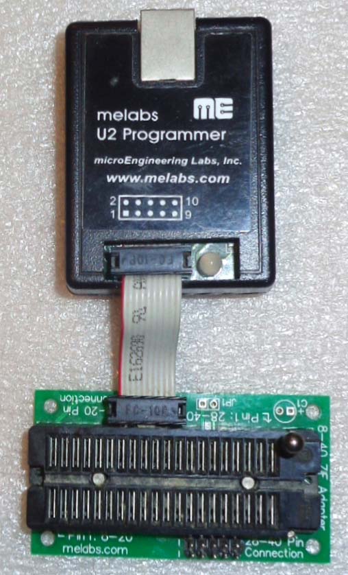
FIGURE 16. My seasoned ME Labs U2 programmer.
The PCB provides the standard six-pin Microchip ICSP header. All Electronics sells the header strips used; cut to six pins and solder to the board. If using U2 (or other ZIF type programmer), use a 14-pin DIP socket for the PIC so you can remove and reinstall it.
Whereas the PCB has provisions for the Molex connector, you could solder four wires to the board, run them out a hole, and add a garden-variety four-pin connector outside the enclosure. The last touch is to solder the interface wires to the board (Figure 17).
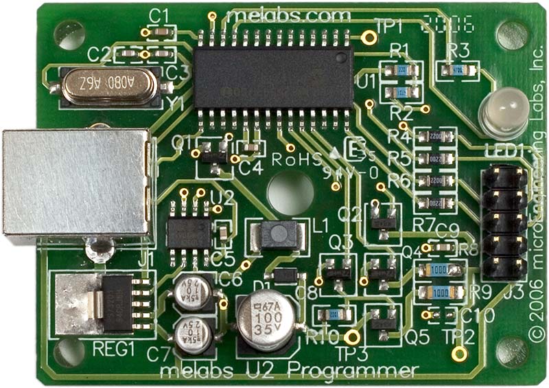
FIGURE 17. Finished controller.
If you have a layout already planned, cut them just a little long. Otherwise, cut them about 3’ (one meter approx). I’m using:
Battery Positive: 20 AWG Red
Chassis Ground: 18 AWG Black
Coil: 18 AWG Orange
Mag Trigger: 20 AWG Yellow
Modifying the Enclosures
The Hammond 1455C802 (main controller) has optional end plates with mounts (used for this project; see Figure 18). Although they do add a bit of cost, they make mounting to the go-kart more secure. Drilling the controller housing is rather easy, as we mostly need round holes.
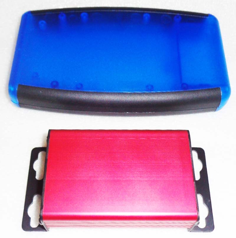
FIGURE 18. Hammond enclosures used for this project; programmer top, controller bottom.
I’m using a rubber grommet to insulate the wires from the housing where they pass through. Harbor Freight sells grommet kits with sizes ranging from 1/4” (6.35 mm) to 1” (25.4 mm). The 5/16” (8 mm) size uses a 5/16” drill bit and has a 3/16” (4.75 mm) hole; perfect for our four wires. Auto parts stores usually carry them in the “HELP!” Section (look for red labels).
For the main wires, we need a 5/16” hole near where the wires connect to the board. Place it rather high to reduce the bend transitioning from the board to the hole, but not too high as the grommet still has to clear the underside of the housing.
After drilling, carefully insert the grommet. A small screwdriver and a little oil (WD-40) helps. Also, install it from the front, as there will be scrape marks on the back side.
The vacuum nipple needs a hole as well. Align your end plate with the housing so that you can center the nipple from the top and mark your end plate. Next, do the same from a side view and mark. (You could also measure.) The goal is to create crosshairs that indicate where the center of your hole should go.
The hole needs to be about 1/4” (not critical). The programmer connector can be accessed through a round hole (even though the connector is square), and sealed with a round plug or electrical tape. All Electronics currently sells a small (about 1/4”) square hole punch for about $10 capable of squaring the aluminum end plates of our enclosure.
Align the end plate up to the board and (from above) mark the center of the connector. Repeat the process from the side. Where the two marks intersect is the center of the connector, and where you put your hole.
If you want to eliminate the hole for the Nextion programmer, you could skip drilling the programmer side end plate, remove it for programming, then install it when done. Also, you could use the optional end plates with mounting tabs for your finished project. Drill the flat end plates that come with the enclosure for tuning, then swap out for the bracketed end plate when done.
The plastic enclosure for the Nextion is a bit more involved. We first need to make a rectangular hole in the top, just large enough for the raised portion of the screen to fit (2.17” x 3.38”, 55 mm x 85.5 mm). We then need to mark our mounting holes and drill. I used a Dremel tool with a cutting disc to make the cut for the Nextion screen.
First, I use tape to mark my lines, then carefully cut along the edge of the tape. Finish work is done by hand with a file (Figure 19).
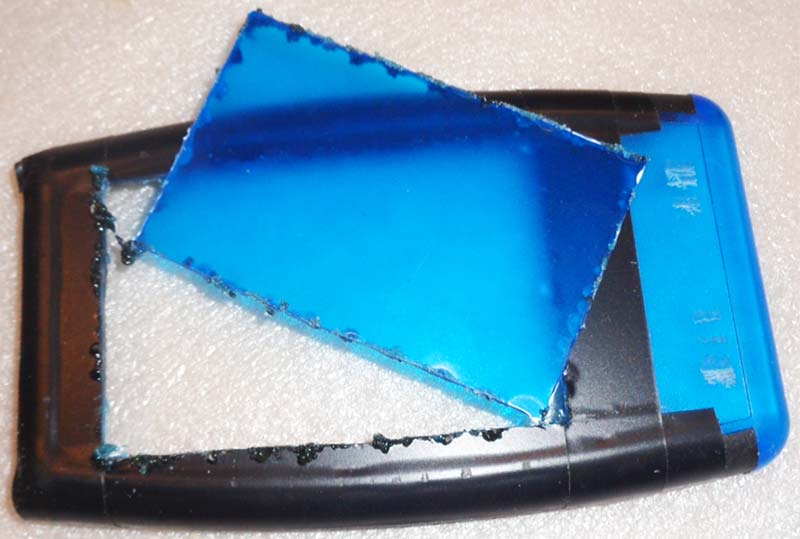
FIGURE 19. Rough cut hole for the Nextion screen.
With our big hole cut, use a #31 drill bit and mark where the screws go (x4), then drill them with a #25 bit (Figure 20). Finally, drill a 5/16” hole in the top end and add a grommet for the cable.
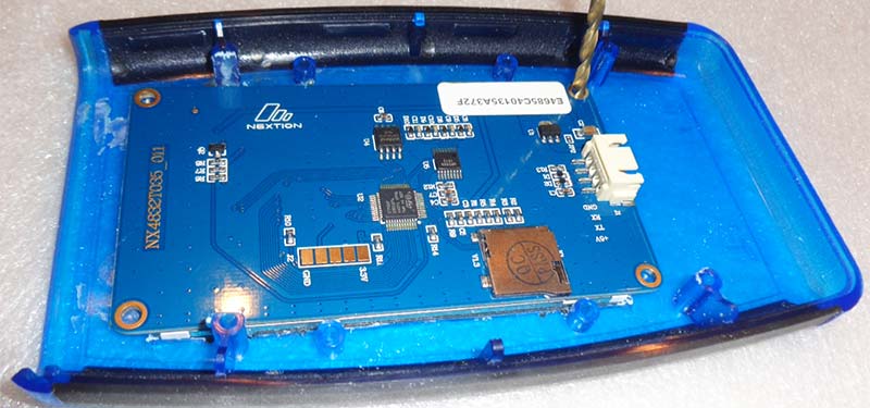
FIGURE 20. Marking where mounting holes need to be drilled.
I found the EM noise from the coil tended to scramble the UART signals. The fix was using a shielded cable. I spliced the cable to the Nextion wires (solder and heat shrink) and used a Molex connector for the controller connection (see the Parts List). The shield is also the electrical ground connection.
Tie the cable in a knot or use a pull tie inside the programmer enclosure to prevent it from pulling out. I had to adjust the clearance in the battery compartment to clear the connector, as well as some of the screw tabs inside to clear the Nextion screen.
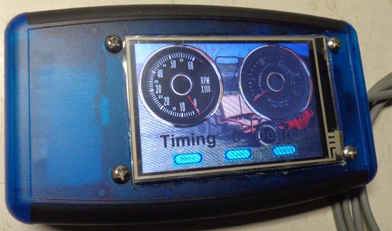
Finished Nextion programmer.
Options
The schematic illustrates what the PCB is designed to do. Feel free to modify it. You may consider trying an opto-isolator (which can be had in a six-DIP package) to replace the SMT MAX9924. I tried to make sure any unused pins had a trace to a spare hole to tap for your own purposes.
The PCB has provisions for a pot, though we didn’t use one for the article. If you’re working on a pump, generator, garden tractor, or other piece of equipment, and just want to experiment with adjusting a fixed timing, this pot provision will allow for that. This would effectively eliminate the need for the Nextion display.
If you need automotive grade wire for your project (used for this article), Waytek Wire (www.waytekwire.com/products/1453/Wire-Cable) has the best prices; although they are more expensive than All Electronics generic wire.
As discussed, I used Hammond enclosures for this project. You aren’t obligated to use these exact boxes for your project. If you have other enclosures laying around that will fit the bill, feel free to use them. In fact, you can alter the size of the PCB to fit what you want.
Also, the Parts List shows special end plates for the controller enclosure. They allow solid mounting, as they have mounting tabs. They aren’t required. However, without them, you’ll need to find a way to permanently mount the controller to your go-kart/mini-bike/lawn mower (etc.). This may be custom brackets or even (gasp) electrical or duct tape (please don’t!).
If you’re comfortable writing your own software, you can tap the unused pins of the PIC to create your own inputs/outputs to suit your needs. I’ve seen turbos, nitrous, fuel injection, and other really cool stuff added to go-karts. You could even utilize the PWM function of the PIC to integrate your own battery charge circuit.
Many engines came with an alternator/generator (part of the flywheel assembly). Do your research and you may find a quick and inexpensive way to charge the battery as you drive.
Conclusion
With the PCB file and Parts List, it’s mostly assembly work. Drilling and cutting the enclosures is standard for custom controllers. Next time, we’ll delve into the PBP3.1 software to bring this hardware to life. NV
Parts List
| Component |
Value |
Part Number |
Supplier |
| C1 |
.047 µF |
445-173599-1-ND |
Digi-Key |
| C2 |
10 µF |
P10425CT-ND |
Digi-Key |
| C3 |
.1 µF |
478-11023-1-ND |
Digi-Key |
| C4 |
.1 µF |
478-11023-1-ND |
Digi-Key |
| C5 |
100 µF |
493-5916-1-ND |
Digi-Key |
| C8 |
47 pF |
445-173499-1-ND |
Digi-Key |
| D4 |
1N4001 |
1N4001RLGOSCT-ND |
Digi-Key |
| D5 |
1N4001 |
1N4001RLGOSCT-ND |
Digi-Key |
| D7 |
1N4007 |
1N4007FSCT-ND |
Digi-Key |
| Q1 |
GB14C40L |
942-IRGB14C40LPBF |
Mouser |
| R1 |
10K |
CF14JT10K0CT-ND |
Digi-Key |
| R2 |
10K |
CF14JT10K0CT-ND |
Digi-Key |
| R3 |
10K |
CF14JT10K0CT-ND |
Digi-Key |
| R4 |
51K |
S51KQCT-ND |
Digi-Key |
| R6 |
10 |
PPC10W-1CT-ND |
Digi-Key |
| R7 |
4.7K |
CF14JT4K70CT-ND |
Digi-Key |
| R8 |
22K |
CF14JT22K0CT-ND |
Digi-Key |
| R14 |
1M |
1.0MQBK-ND |
Digi-Key |
| RP1* |
50K |
3296W-503LF-ND |
Digi-Key |
| U1 |
LM7805 |
926-LM7805CT |
Mouser |
| U2 |
PIC16F18426 |
PIC16F18426-E/P-ND |
Digi-Key |
| U3 |
MPXA6115 |
MPXAZ6115AP-ND |
Digi-Key |
| U4 |
MAX9924 |
MAX9924UAUB+CT-ND |
Digi-Key |
| Enclosure |
Controller |
546-1455C802RD |
Mouser |
| Encl Ends** |
Controller |
546-1455CFBK |
Mouser |
| Enclosure |
Programmer |
546-1553DTBUBKBAT |
Mouser |
| Connector |
Molex |
WM1814-ND |
Digi-Key |
| Connector |
Molex |
WM11225-ND |
Digi-Key |
| Terminals |
Molex |
WM1842-ND |
Digi-Key |
| Shielded Cable |
Three-Wire |
3CS22 |
All Electronics |
| 18 AWG Red |
Red Stranded |
18RD-25 |
All Electronics |
| 18 AWG Black |
Black Stranded |
18BK-25 |
All Electronics |
| 18 AWG Orange |
Orange Stranded |
18OR-25 |
All Electronics |
| 20 AWG Blue |
Blue Stranded |
20BL-25 |
All Electronics |
| Header Pins |
0.1” Straight |
SHS-40 |
All Electronics |
| Grommet |
1/4” ID |
GMT-20 |
All Electronics |
| Display |
3.5” Display |
NX4832T035 |
Nextion.Tech |
| (2) #40 x .4” Screws |
|
|
|
| (2) #40 Nuts |
|
|
|
| * Not used in project |
|
|
|
| ** Optional |
|
|
|
Resources
Microchip
www.microchip.com
Digi-Key
www.digikey.com
Mouser
www.mouser.com
Nextion
https://nextion.tech
All Electronics
www.allelectronics.com
ExpressPCB
www.expresspcb.com
Waytek Wire
www.waytekwire.com/products/1453/Wire-Cable
Downloads
What’s in the zip?
PCB File
Schematic File
Resource Guides