Give Our Controller Life — Adding PBP3 Software!
Last time (Issue-2 2020), we designed the PCB (printed circuit board) and other hardware for our controller. This round, we’ll design the software. Special kudos to Charles Leo at ME Labs. He put other things on hold to create an update for PBP3 to include the relatively new PIC16F18426 used for this project. What makes this PIC special includes: seven timers (we need all of them); comparator (identifies the Intake stroke for MAP read); DAC (for comparator reference), 256 byte EEPROM (for our Timing Table & Dwell); UART (to talk to the Nextion); Peripheral Pin Select (PPS, to Enable/Disable UART); 32 MHz HFINTOSC; and 500 kHz MFINTOSC oscillators.
Of course, we could have stepped up to a 28-pin PIC18F offering but, in reality, we could fit this on an eight-pin PIC12F processor. The 16F18426 is 14-pin which leaves spare I/Os for your own custom options (including debugging) and allows the ICSP (programming) pins to remain dedicated.
Overview
The algorithm covers several functions. First will be communication with our Nextion programmer (UART). The tune must be saved to the EEPROM and read back into the Timing Table (& Dwell) on initial start. RPM is calculated from Timer 1 using the MFINTOSC clock source, triggered by INT. Vacuum is read from the ADC (analog-to-digital converter), then converted to kPa, but at a critical moment initiated by Timer 5. Ignition Timing must be calculated about 1X per engine revolution (INT trigger), with the result processed and fed to Timer 3 to fire the coil. Timer 2 controls Dwell, turning the coil off. Timer 4 throttles UART rotations of RPM, Vac, and Timing packets. Timer 6 masks the second magneto pulse. Timer 0 acts as a watchdog timer, interrupting only if the engine is not running.
The program is written in PBP3.1 PIC BASIC Pro. Why BASIC? I bought a book on Digital Signal Processing. The author wrote his example code in BASIC, as (in his words) anybody knowledgeable in programming can easily port BASIC to C, ASM, FORTRAN, COBAL (old book), or anything else.
The SmEngTimCont.pbp is in the article downloads. I tried to heavily comment for ease of understanding. Comments not only give a blurb about what a particular line of code does, but reference the PBP3 Reference Manual, the Microchip PIC16F18426 datasheet, and Nextion manual(s). I wanted to help someone break into programming without resorting to an Arduino.
We’ll cover the mechanics here, but not the full program. If you’ve been wanting to learn microcontrollers, I strongly encourage you to spend some time with the commented code and this article.
The PIC code can be broken into three categories: control timing; talking to the Nextion; and Interrupt Handling. Talking to the Nextion involves receiving commands and data through the UART RX; transmitting RPM, Vac, Tim, and programming parameters (Timing Table & Dwell) through the UART TX. Controlling timing requires processing RPM, calculating timing, firing the coil, and turning the coil off. The Interrupts are handled using DT_INTS (Daryl Taylor Interrupts), named for the late genius (RIP 2014). The software is broken down into:
- Commented Header
- DEFINEs
- EEPROM Preload Values (Nextion Tuning Page Table Values)
- CONFIGuration Bits
- Aliases
- Variable Declarations
- Functions (SubRoutines)
- Interrupt Service Handler (ISR)
- DT_INTS Include Files
ME Labs PBP3.1
PIC BASIC Pro3 (PBP3) is a compiler. The output is a hex file; the same basic output you get using XC8 or ASM. My MCU journey started with the PICAXE, then moved on to PBP3. I now do lots of programming with MPLABX and XC8/16.
PBP3 has advantages found nowhere else that keeps me coming back, which is why I chose to use PBP3.1 for this project. ME Labs offers a Student Version of PBP3, as well as a 30 day free trial of their Gold Version. The PIC16F18426 requires the Gold Version.
Preliminaries
Grab the SmEngTimCont.pbp file from this article’s downloads. You can open it in PBP3 or any text editor. The header just sets the stage. The first command is CLEAR, which resets all variables to zero. Oscillator speed is DEFINE’d as 32 (MHz), and we are DEFINE-ing a special INT-errupt HANDLER as INT_ENTRY.
The EEPROM preload values (DATA @x) are a good starting point. The stuff between #CONFIG and #ENDCONFIG are the CONFIGuration bits (see the datasheet). We must Declare Interrupts used with DT_INTS next. The Aliases allow us to use a short-cut name for PORT pins and Interrupt related flags. All variables must be declared before use, so they are placed near the top before any actual code.
A BYTE equals eight bits, WORD equals 16 bits (both unsigned). NexFlags is declared as a BYTE, but then each bit is assigned a unique name; Nflag VAR NexFlags.0 identifies Nflag uniquely but is bit0 of NexFlags. These bits are used mostly in the ISR and Main: loop.
<pTab0 : pTab3> are also sources of flags (a Table cell value changed), as is Work. TimTab VAR BYTE[32] is the Timing Table buffer containing (4X8=) 32 bytes; NexBuf VAR BYTE[16] is the Nextion transmission buffer with 16 bytes.
Functions
The first function is Init:. This is where we set the Special Function Registers (SFRs) that control the peripherals. First, the internal oscillator (HFINTOSC) is configured for 32 MHz. Next, Pertinent Interrupt Enablers (PIEx.y) are listed. Note that INTCON.0 determines the INT Interrupt Polarity. You may need to change it for your engine. (More on that later.)
From there, the PORT related SFRs are configured; TRISx, ANSELx, WPUx, ODCONx, INLVLx, and SLRCONx. The ADC is connected to our MAP sensor (RC3) and configured for eight bits (Left-Aligned).
With PPS, INT is tied to RC3, TX1 to RC4, CMP1 to RA2, and our RX1 pin is configured as a normal I/O for now. If the Nextion is connected, we’ll reconfigure RA5 as our RX1 pin later. The PMDx feature allows us to disable peripherals we aren’t using to cut energy use.
UART is set for 19200 baud. This is fast enough to cover the bases, while robust enough to live in a rather noisy environment.
TIMER0 will interrupt if RPM < 230. TIMER1 measures the pulse-to-pulse period (one engine revolution, Tach). TIMER2 uses a 1:8 prescaler and 1:10 postscaler to count at 0.000 100 second (X.X ms) intervals for Dwell. TIMER3 uses the same MFINTOSC (500 kHz) as TIMER1 to trigger the coil after Fire counts. TIMER4 uses a 1:64 prescaler and 1:5 postscaler to yield 0.01 second increments for throttling data transmissions to the Nextion for Tune, Gauges, and DataLog Pages 10X/Second.
TIMER5 is clocked with the same MFINTOSC as TIMER1/3, triggering an ADC read of the MAP sensor. TIMER6 masks the magneto’s second pulse. The Comparator indicates when we’re on the Intake Stroke (versus the Exhaust Stroke), using the MAP signal as the Negative Input, and the DAC Output for the Positive Input. Finally, we configure the DAC peripheral.
If you remember from the last article, there’s a one megohm pull-down resistor on the UART RX line of the PIC. When the Nextion is connected, it will pull this line high. We check for the presence of the Nextion at the end of Start: and again at the beginning of Main:.
When the Nextion first starts, it shoots out a string of data letting us know it’s working and is ready for action (see “7 - Format of Nextion Return Data” in the Instructions). Instead of sifting through all that unnecessary protocol, Start: allows us to skip it entirely (along with a few other preliminary duties).
Start: just sets the stage to get things rolling, including preloading variables, grabbing a barometric pressure reading (Get_Baro), loading our X-Y Table & Dwell (Load_Table), enabling Interrupts, checking for the Nextion programmer, and enabling UART if present.
Main:
The Main: loop mostly checks for flags and then LOOPs. The Interrupt Handlers set flags for Main: to act upon. Main: looks to see if the Nextion sent any data (Nflag), if we completed another engine cycle (Mag), if our ADC just grabbed the latest MAP value (MapReady), if it’s time to send RPM/Vac/Tim to the Nextion (RotX), or if it’s okay to send another Timing Table value (tLoad) when we use the Tune Screen on the Nextion. The top code checks for the Programmer in case it’s connected later.
Other Subroutines
Load_Table: READs TimTab[] and Dwell from the EEPROM and sets T2PR accordingly.
Burn_Table: WRITEs any changed Table values (or Dwell) to the EEPROM. Changed values are determined by the pTabX[] flags.
Get_Nex: Deciphers received Nextion UART packets. (Note the Command Listing.)
Send_Table: Puts wheels in motion to send the entire TimTab[] plus Dwell to the Nextion.
Send_Cell: Is one of the wheels; it sends the next TimTab[] cell to the Nextion by loading the NexBuf[] buffer with the next Command string; also used when we change a single cell value with the “+/-“ buttons or the keypad.
Rot_Data: Initiates the next round of RPM/Vac/Tim data sends.
Get_RPM: Works the math to convert TIMER1’s Tach to RPM.
Get_Tim: Uses PRM (X) and Vac (Y) to choose the proper TimTab[] Look-Up value, process it, then load it into the variable Fire. This is similar to what we did to highlight the active cell on the Nextion. The TIMER1 ISR loads Fire into TIMER3 to fire the coil, and loads PeakVac into TIMER5 to read the MAP; turning both on and enabling their Interrupts.
Send_RPM: Loads NexBuf[] with rpm.val=XXXX and terminates with $FF,$FF,$FF. It then activates the UART TXIE to send it byte-by-byte to the Nextion. Send_Vac: does the same for Vac, Send_Dwell: transmits Dwell, and Send_Tim: sends the current Timing (Tim) value.
Start_TX: A function called from several subroutines; initiates sending of the NexBuf[] packet to the Nextion.
Get_Baro: Takes a snapshot of the barometric pressure from the MAP sensor before the engine starts and adjusts the DAC output accordingly.
Interrupt Service Handler (ISR)
The ISR tackles all our time-critical tasks. Everything else is handled in a regular function. DT_INTS_PIC16F18426.pbp (in the downloads) parses through the Interrupt Flags (PIRx.y) and filters them with the Interrupt Enable (PIEx.y) Registers to determine what triggered the interrupt. It then CALLs (or GOTOs) the function specified at the top of the code (ASM : INT_LIST…).
Get_Tach: is five parts: clear the INT IF and disable the IE; put the TMR1 value into Tach; enable TMR6 to mask the magneto’s second pulse; fire the coil if in low RPM mode, otherwise load TMR3 with Fire to trigger the coil; and enable TMR5 to read MAP. Both Tach and Fire are WORD sized variables, as are the TMR1 and TMR3 Registers (TMR1L & TMR1H : TMR3L & TMR3H).
To load the TMR1 Register values into our Tach variable; Tach.LOWBYTE = TMR1L : Tach.HIGHBYTE = TMR1H. We start by clearing the INTF Interrupt Flag: INTIF = 0 and disable INT Interrupts: INTIE = 0. Next, we turn Timer 1 off: T1CON.0 = 0 and save TRM1 to our Tach. We then clear the Timer1 Counter Register: TMR1L = 0 and TMR1H = 0, turn Timer 1 back on (T1CON.0 = 1), and finally clear TMR0 (our engine stall watchdog): TMR0L = 0 : TMR0H = 0.
On initial start (Cold = 1), fire the coil when the magneto triggers, not using Timer 3 and Fire (for six pulses only). Stock ignition timing is a compromise; the magneto is fixed (bolted to the engine) and therefore timing is fixed. Lower load ranges really don’t generate much NOX emissions.
To allow for more appropriate timing at higher loads and RPMs, timing is actually too advanced for no-load conditions. Firing the coil when the magneto triggers retards ignition timing a bit. The engine can actually smooth out versus stock timing. This IF clause also checks for the FC Flag, which is set near the bottom of the routine. It should have been cleared when we turned the coil on in Spark. If for some reason it didn’t happen, there would be a misfire without this part of the IF statement. When this happens, the spark fires late, but at least it fires. [I discovered the random misfires while doing emissions testing (covered next time). The FC flag reduced misfires and emissions.]
If in a normal load range, the ELSE part loads TMR3 with the Fire, which we calculate in Get_Tim:. It clears TMR3IF, sets TMR3IE, and turns TMR3 on. Next, it loads and enables TMR5 and its interrupt and exits the ISR (GOTO Home). Lastly, it clears FC.
Stall: Clears RPM to zero and can only instantiate if RPM < 230.
Quench: Is the TMR2IF ISR that turns the Coil off (Coil = 0) after Dwell time. It clears the flag, turns the coil off, turns Timer 2 off, then exits.
Spark: Is the Timer 3 ISR that initiates the coil firing. It clears the TMR3IF and IE, turns the Coil on, configures Timer 2 for Dwell, turns Timer 3 off, then exits.
Rot: Simply sets the RotX Flag for Main: to send the next batch of data to the Nextion.
Suck: Is triggered by Timer 5 to perform an ADC read on our MAP sensor at 120 degrees after INT triggers. First, it clears Timer 5 and ADC IFs, enables ADCIE, initiates an ADC read, turns Timer 5 off, then exits.
Listen: Deciphers received packets from the Nextion. First, it checks for Framing or Overrun Errors and deals accordingly. Next, it tests the HinBit (IF HinBit = 1) to see if it’s receiving Hin0 or Hin1, and loads the appropriate Hin0_1 variable with RC1REG. No IFs are cleared, as it’s automatic when we read the RC1REG Register.
Talk: Cranks out the NexBuf[] as quickly as the UART can handle. The TX1IF is set when the TX1REG is empty. It starts by checking if there’s a new BYTE to send; IF NexBuf[NexIndex] = 0. If the result is 0, it aborts. Otherwise, it shoots it out and increments the NexBuf offset variable; NexIndex = NexIndex + 1.
Get_Map: Is triggered by the completion of our ADC read. We clear ADIF and move ADRESH initially to b0 (ADRES needs to be read). If the Comparator1 output = 1 (IF CM1CON0.6 = 1…), we move b0 to MAP and set the MapReady flag, clear IF, and disable IE.
Mask: Since the magneto outputs two pulses, the MAX9924 does as well. We need to mask the second pulse, which is handled by Timer 6. This Interrupt Handler turns our INT Interrupt Enable back on (INTIE = 1) so it can detect new magneto pulses.
Home: The last line in each ISR Function is GOTO Home. This is where we trigger ReEnterPBP.bas to restore Register values and move the Program Counter (PC) to where it was when the Interrupt occurred with the ASM Command @ INT_RETURN.
Deciphering Nextion Command Codes (Get_Nex:)
Get_Nex: deciphers UART transmissions received from our programmer. The bulk of the subroutine is a SELECT CASE, sorting through Hin0. (XC8 would use the switch() command.) If you recall from Part 4, the Nextion sent out sys0, sys1; Command Code, Value. Our PIC receives Hin0, Hin1. So, SELECT CASE Hin0 decides the meaning of the Command Code. It starts by filtering out non-related transmissions: CASE IS < $25. (XC8 and ASM denote hex as 0x25 or 25h, while PBP uses $25.)
- $25 (37d) : Enable/Disable Automatic Data Load of RPM, Vac, and Tim
- $26 (38d) : Change Rate of Data Rotation; Hin1 X 10 ms
- $27 (39d) : Send Entire Table (Initial Tune Page Load)
- $28 (40d) : Timing Table TimTab[0]
- $29 (41d) : Timing Table TimTab[1]
- --- : --- --- ---
- $47 (71d) : Timing Table TimTab[31]
- $48 (72d) : Dwell Value
- $49 (73d) : Save Command; Burn Values to EEPROM
- Plus a few others
These Command Codes were listed in Part 4. Nflag = 0 clears the flag.
Sending Data (Send_abc)
Get_Nex: takes care of deciphering received data. Subroutines starting with Send_abc load the NexBuf[] buffer with an ASCII string to be sent over UART to the Nextion. According to the Nextion Instruction Set, a proper Command is structured: rpm.val=2345 255 255 255.
The ARRAYWRITE command allows us to easily load NexBuf[] with ASCII characters. Therefore ARRAYWRITE NexBuf, [“rpm.val=”] puts the first part of our UART transmission into our NexBuf[] buffer. The actual RPM of “2345” must be sent as ASCII in four separate bytes: $32, $33, $34, and $35. Consider:
IF tRPM > 1000 THEN
b0 = tRPM / 1000 ;Get the Xxxx Value
NexBuf[8] = b0 + $30 ;Convert it to ASCii
tRPM = tRPM - (b0 * 1000) ;Subtract the Xxxx Value from tRPM
ELSE
NexBuf[8] = $30 ;If tRPM < 1000, Zero (ASCii)
ENDIF
IF tRPM > 100 THEN
b0 = tRPM / 100 ;Get the xXxx Value
NexBuf[9] = b0 + $30 ;Convert it to ASCii
tRPM = tRPM - (b0 * 100) ;Subtract the xXxx Value from tRPM
ELSE …
The ARRAYWRITE command puts the ASCII character “r” into NexBuf[0], ASCII “p” goes in NexBuf[1], “m” loads to NexBuf[2], and so forth. Up to the numbers, NexBuf[] is filled from byte 0 to 7. Therefore, the ASCII representation for the 1000’s RPM value is assigned NexBuf[8]. Instead of mutilating our valuable RPM variable, we create a temporary variable tRPM to butcher: tRPM = RPM.
Start by dividing tRPM / 1000 to get our Xxxx value, convert it to ASCII, then subtract Xxxx from tRPM. The process is repeated for the hundreds xXxx, tens xxXx, and finally ones xxxX. To satisfy the Nextion, the End of Transmission $FF, $FF, $FF (255, 255, 255) must be included in the package:
FOR b0 = 12 TO 14
NexBuf[b0] = $FF ;Nextion’s End of Message Sequence
NEXT b0
Lastly, different packets will be of different lengths. To indicate the end, load the last byte of the packet with a zero:
NexBuf[15] = 0 ;Tells Us To Turn UART TX INT Off
Looking through the different Send_abc routines, you’ll see that some numbers are altered to fit the packet, but the concept is the same. After we load the NexBuf[] buffer, we have to send it to the Nextion using UART. Start_TX: is just three lines that clear our NexBuf[] offset counter (NexIndex = 0), sets the Tbusy flag, and enables TXIE Interrupts. Actual transmission is handled in the ISR, Talk:. We aliased PIE1.4 as TX1IE. Therefore, we can use:
- TX1IE = 1
- PIE1.4 = 1
- @ INT_ENABLE TX1_INT
As long as we alias TX1IE VAR PIE1.4, all three options work.
Get_RPM:
This specific subroutine requires an explanation. The formula for determining RPM = (Timer Clock Speed / Timer Value) * 60 Seconds which is: RPM = (500,000 / Tach) * 60. Since we’re using MFINTOSC for our Timer 1/3 clock, we need to be able to handle the value 500000 which is larger than a WORD (65535) size. The approach taken is to treat the math like I was taught in fourth grade, using Borrow, Carry, and Remainders at 1/10 the value.
DT_INTS
The observant will notice absolutely no mention of DT_INTS in the PBP3 manual. Daryl Taylor developed this after the manual was written. Officially, it’s not part of the PBP3 package. If you go to http://dt.picbasic.co.uk, you can get the most comprehensive and codified information on DT_INTS. It’s an online book with numerous contributors (including me). As mentioned, Daryl passed away in 2014. Since then, new PICs have hit the market. The original DT_INTS.bas didn’t have provisions for the new peripheral interrupts. The book not only shows you how to use DT_INTS, but also how to custom tailor Daryl’s original software for just about any eight-bit PIC.
The PBP3 manual covers “ON INTERRUPT GOTO” and ASM Interrupts. To try to keep things simple for the article, I first tried ON INTERRUPT GOTO. After fighting inconsistencies for months (one excuse for the late article), I called Charles Leo at ME Labs. About an hour into dissecting individual lines of code, he finally proclaimed, “You’re using On Interrupt Goto for an engine ignition timing controller?!?” He told me that it merely polls the IFs and jumps to the ISR at the earliest convenience.
ASM Interrupts add syntactic complexity, so I chose to use DT_INTS. The INCLUDE file (DT_INTS_PIC16F18426.pbp; in the downloads) is custom tailored to this PIC, as per the online book instructions (I wrote that section for the book). It also requires ReEnterPBP.bas.
Key Concepts
The first thing to grasp is that advancing or retarding ignition timing is controlled through Timer counts. As RPM changes, so do the Timer counts for any given Timing/RPM value. We program our Timing Table in degrees of engine rotation. In order to execute, we need to know how many Timer counts equal one degree.
Measuring a 360 degree Period (Tach) is a Timer 1 job, while carrying out the firing of the coil (Fire) is handled by Timer 3; both of which are clocked by the same source — MFINTOSC (500 kHz). Our ISR uses the variable Tach to capture the Timer 1 counts, which is then converted to RPM and Degrees in Get_RPM:.
If we were to retard timing, we simply receive an INT Interrupt, wait the retarded Timing value by (Deg x Tim), and fire the coil. However, to advance timing, we must anticipate the INT trigger. In Get_Tim:, close to the bottom we establish a few values: Tim = TimTab[b0] and TimTime = Deg * Tim. This converts our X-Y Table value to Timer 1/3 counts. Back in Main:, we established Comp = (T2PR * 5) + (Vac << 2) which compensates for Dwell and sudden throttle changes.
With these values, Fire = (65535 - Tach) + TimTime + Comp. A Timer 3 Interrupt occurs when TMR3H_L rolls over from 65535 to 0. We preload Fire with (65535 -- desired value). The value we enter into the Nextion n0 >> n31 Timing Table is the Tim part. Deg is calculated as Tach divided by 360, giving us a Timer1/3 value for one degree of engine rotation.
Since the coil fires AFTER we release the ground (when Timer2 Interrupts), we must take that into consideration with Comp = (T2PR * 5)… which adds Dwell back in to compensate. The Vac << 2 line adds an advance to compensate for shorter Tach periods on acceleration.
Finally, Fire is loaded with the roll-over value (65535), minus our engine revolution Period Tach, plus our advance, plus Comp. Frankly, you could eliminate the Nextion programmer and hard code your Table. It would be quite an arduous task to isolate the proper cell to modify with virtually no data (RPM/Vac) to base changes on. The features in the Nextion Tune Page show us where we are in our Timing Table, so we know where to make changes as we drive. The active cell is highlighted in red, with the Timing value being executed.
We can monitor RPM and kPa in relation. Changes are made on-the-fly, as opposed to shut down, reprogram, and retest. The large easy-to-read gauges allow us to verify as we drive. The DataLog screen plots events where we can review them at our leisure, with scrutiny.
Scope Shots
Take a look at Figure 1.
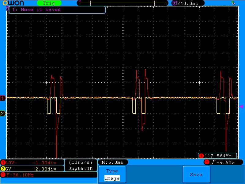
Figure 1. Raw magneto signal in red, MAX9924 output in yellow; Honda 5 HP engine.
The red trace is the Honda magneto output while the yellow trace is the MAX9924 output. Figure 2 shows the Timer 6 Mask in yellow over the MAX9924 in red.
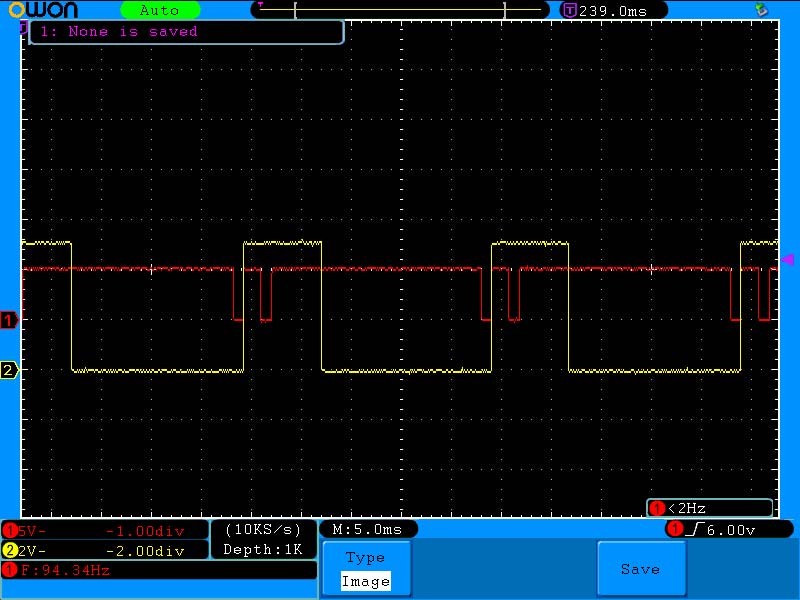
Figure 2. MAX9924 output in red; Timer 6 Mask output in yellow.
Figure 3 shows the vacuum signal from the MPXA6115 in yellow and COMP1 output in red.
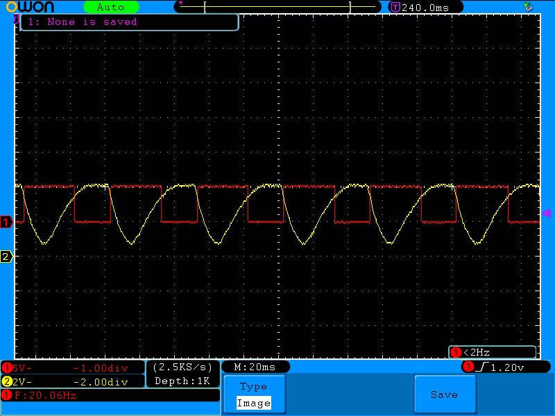
Figure 3. Vacuum signal from the MPXA6115 in yellow; comparator output in red.
Figure 4 shows Timer 5’s ADC read (in yellow) of the vacuum signal (in red).

Figure 4. Vacuum signal in red; Timer 3 activates an ADC read at the yellow timing marks.
Figure 5 shows the mag signal in red and the coil signal in yellow.
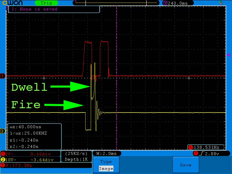
Figure 5. Honda magneto output in red; coil firing in yellow. Note Timer 3 initiates Fire to ground coil, while Timer 2 turns coil grounding off at Dwell.
Figure 6 shows the Honda mag signal in red and the coil driver output in yellow, with five degrees advance.
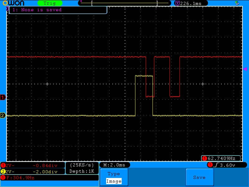
Figure 6. Magneto output in red; coil driver output in yellow with five degrees of timing advance.
Compare Figure 1 to Figure 7.
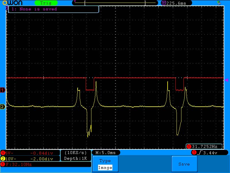
Figure 7. Predator raw magneto output in yellow; MAX9924 output in red.
The Honda magneto generated two negative pulses (Figure 1) on the MAX9924, while the Predator only yields one (Figure 7). After getting the Honda running well, I couldn’t get the Predator to even start. Figure 8 shows the relationship between the MAX9924 output in red compared to the coil driver in yellow.

Figure 8. Predator MAX9924 pulse in red; coil driver output in yellow when INTCON.0 = 1 (INT Inverted Polarity). Timing is too retarded to even get the engine to start.
Changing INTCON.0 from ‘1’ to ‘0’ fixed the issue; refer to Figure 9.
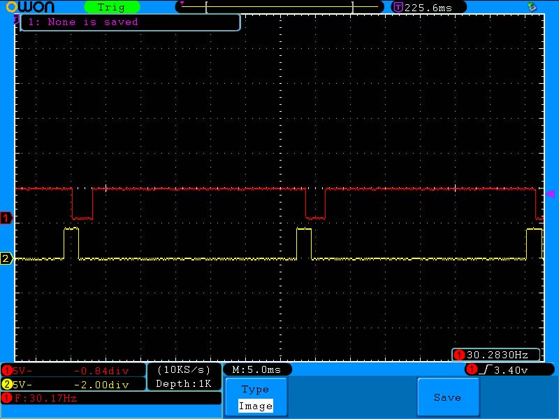
Figure 9. Predator engine when INTCON.0 = 0, INT True Polarity. Now, the same timing table developed on the Honda works on the Predator.
These images should help you better understand what we’re doing.
Programming our PIC
When it comes to burning software to a PIC, there are multiple programmers capable of doing the job. From Microchip, there’s the Snap (low price king at ~$30 US), PICKit 3 (now showing its age and no longer available through Microchip), PICKit 4 (current go-to offering), and the higher-end ICD4 (Figure 10).
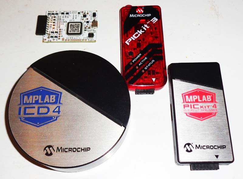
Figure 10. Clockwise from bottom left: Microchip’s ICD4, Snap, PICkit3, PICkit4.
ME Labs offers a useful alternative with their U2 ZIF Programmer (Figure 11), which allows you to put your PIC into the ZIF and hit “Program” from the MicroStudio IDE (PBP IDE).
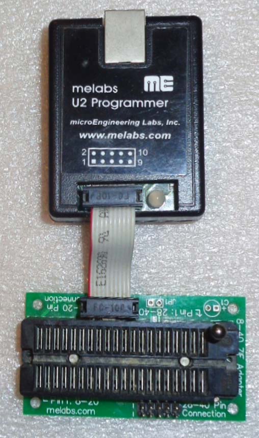
Figure 11. ME Labs’ U2 PIC programmer with ZIF socket.
The PCB board includes provisions for the standard Microchip six-pin ICSP header should you choose to go that route. Almost as an after-thought, open the Nextion program. Click on page0 (Start Screen) and in the Postinitialization tab of the Event pane, add bauds=19200 to set the UART baud rate.
In Conclusion
After learning the basic essentials in Parts 1 and 2 of this series, we built our programmer in Parts 3 and 4. In Part 5, we constructed a lifeless piece of hardware to serve as our actual controller. This time (think Michelangelo’s “The Creation of Adam”), we gave that hardware life.
Next time, we’ll mount a battery, coil, and this controller to a Manco two-seat go-kart and wire it up. We’ll get a baseline, then use the features built into our system to squeeze more power out of a 6.5 HP rated Harbor Freight engine. NV
Resources
Downloads
What’s In The Zip?
SmEngTimCont.pbp
DT_INTS_16F18426.pbp
PICBASIC PRO Compiler (PBP) QuickStart Manual
PICBASIC PRO Compiler (PBP) Reference Manual
Microchip Datasheet