The NixieNeon clock is a product of my love for clocks and electronics. Ever since I was a young child, I have been fascinated with electronics. I remember watching my father build nothing boxes with neon bulbs and 90 volt batteries which would make you tingle right up to your elbows when you touched them (bad influence from my older brother). As the years went by, my primary focus shifted to computers and writing software but still, I enjoy the smell of rosin when soldering and enjoy tinkering with small circuits.
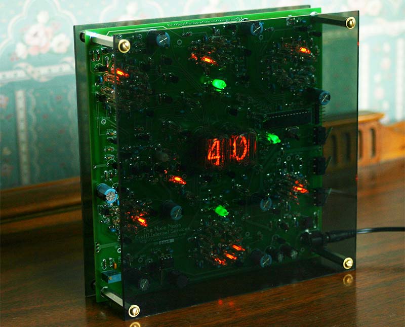
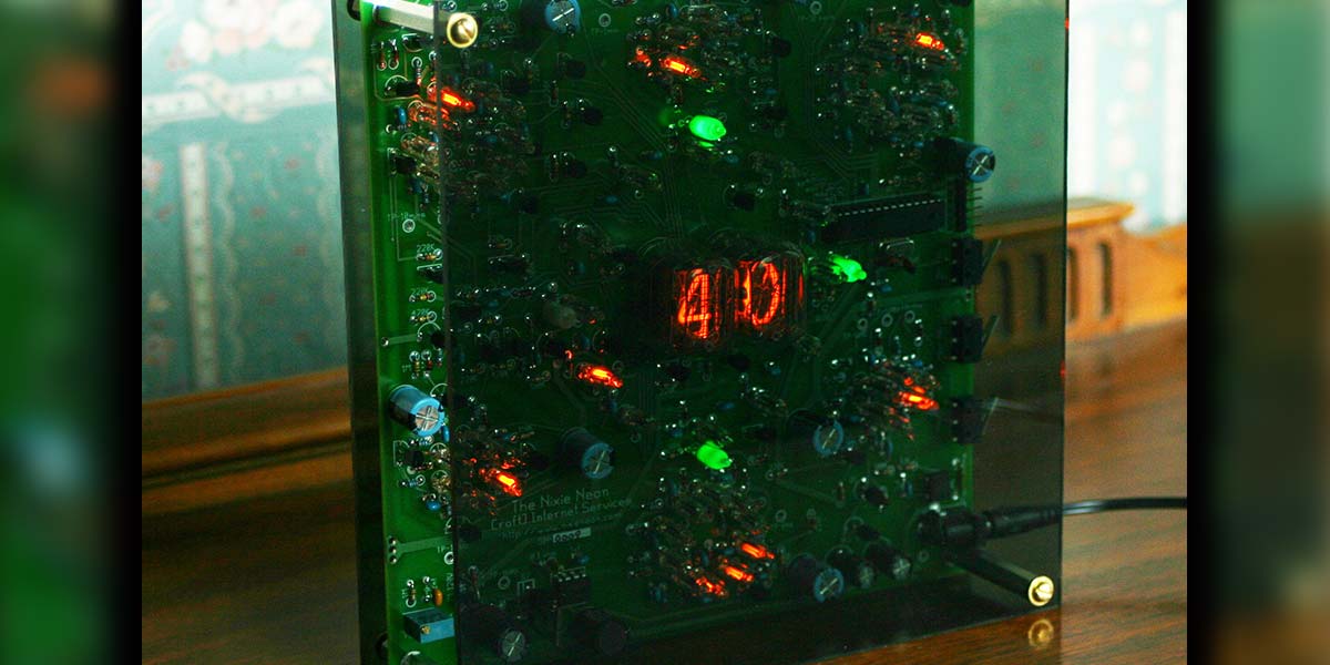
FIGURE 1. The completed clock.
My fascination with clocks was slower to develop. It was awakened when inheriting several very old clocks which were once my grandfather’s.
I have wanted a Nixie tube clock for some time. In the last few years I decided I would build one, but not just another clock driven by a microcontroller where all of the magic of the time keeping was hidden inside a piece of silicon. I wanted a circuit where I could watch it count, like the old skeleton clocks. Scouring through the Internet, I ran across a circuit using neon lamps in a ring counter which then drove the Nixie tubes. At last, my break-through: a clock circuit which was as retro as the Nixie tubes themselves!
At first, I tried to do it without a processor. This worked well, but it had its limitations. First and foremost, the neon ring counters proved to be somewhat erratic over time. Every so often, a bulb would not fire when it should or — just as bad — one would light when it shouldn’t. Either way, this caused the clock to miscount.
After building several clocks of the original design, I decided to add a processor to help hide the occasional miscount; it also helps finding which of the bulbs are misfiring.
To maintain the original goal, the processor does not have an active role in the clock’s operation. It does track the time and will periodically make the rings ‘dance,’ then resets the clock to what it has as the correct time. The ring counters still do the bulk of the job. It can also spin individual rings which hopefully will show bad bulbs. Ultimately, I want to have the processor to monitor the rings to detect miscounts.
Developing this clock has proved to be quite the learning experience for me. From it, I have learned that neon ring counters are quite sensitive. Neon bulbs do not have a consistent behavior from bulb to bulb. As well, the bulbs are sensitive to light. I have also found that neon bulbs can be easily stressed by excessive current. Empirically, I have determined even short periods of excessive current can change their trigger voltage. So, be kind to your neon bulbs.
In the end, the biggest lesson I learned is that time is not on your side with this clock. As the bulbs age, their characteristics change. Over time, there is a good possibility that some bulbs in the clock will not fire or fire when they shouldn’t which will cause it to miscount. It’s not that the bulbs won’t light; they just will not light when they should. For me, I can live with this.
The processor will keep the clock on track for the most part. When a bulb is bad enough or is messing up and making the clock get way off, I’ll just replace it and wait for the next bulb to misbehave.
Circuit Description
The clock consists of a high voltage power supply, seven ring counters, and an Atmel AVR processor. The power supply is shown in the schematic in Figure 2.
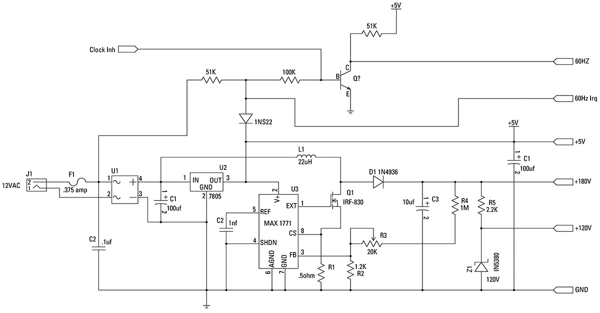
FIGURE 2. Power supply schematic.
It takes 12 volts AC and converts it to DC which drives the Maxim 1771 switching power supply to generate 160 volts. The Maxim 1771 operates by effectively shorting the 12 volts DC to ground through the coil L1 using the MOSFET Q1. When it turns off Q1, this releases the coil from ground and a large positive spike is generated which is then stored in an electrolytic capacitor C3. The diode D1 keeps the capacitor from discharging back though the circuit.
Resistors R2, R4, and the potentiometer R3 make a voltage divider which feeds a small voltage back to the Maxim IC so that it can adjust the pulse’s frequency and duty cycle to regulate the voltage. Resistor R5 and zener diode Z1 are used to regulate this down to 120 volts to drive the ring counters. The AC input is also used to provide a 60 Hz signal to the first ring, as well as an interrupt to the processor.
Three of the ring counters divide by 6, three others divide by 10, and the last ring divides by 12. The divide by 6 rings and the divide by 10 rings are paired to count the 60 Hz down to 1 Hz, the 1 Hz to 1 cpm, and the 1 cpm to an hourly pulse. Each of the rings are similar. The difference being the trigger circuit is different for the first two rings than the subsequent rings.
The first two rings use a single transistor to drive them, while a three-transistor circuit is used to provide clean consistent pulses to drive the remaining rings. In addition to the different triggering circuits, the minutes and 10s of minutes rings have half of the diodes replaced with the base emitter junction of a transistor. Those transistors, as well as others, are used to drive the digits of the Nixie tubes.
The schematic in Figure 3 is indicative of the divide by 10 rings.
Ten-stage ring counter schematic.
It depicts the simpler one-transistor trigger circuit which is used in the first two rings which divide the 60 Hz down to 1 Hz. Notice that the transistor is capacitively coupled to the ring, driving the positive side towards ground in short pulses.
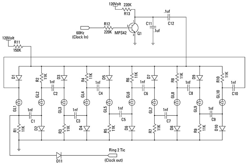
The schematic in Figure 4 is indicative of the divide by 6 rings.
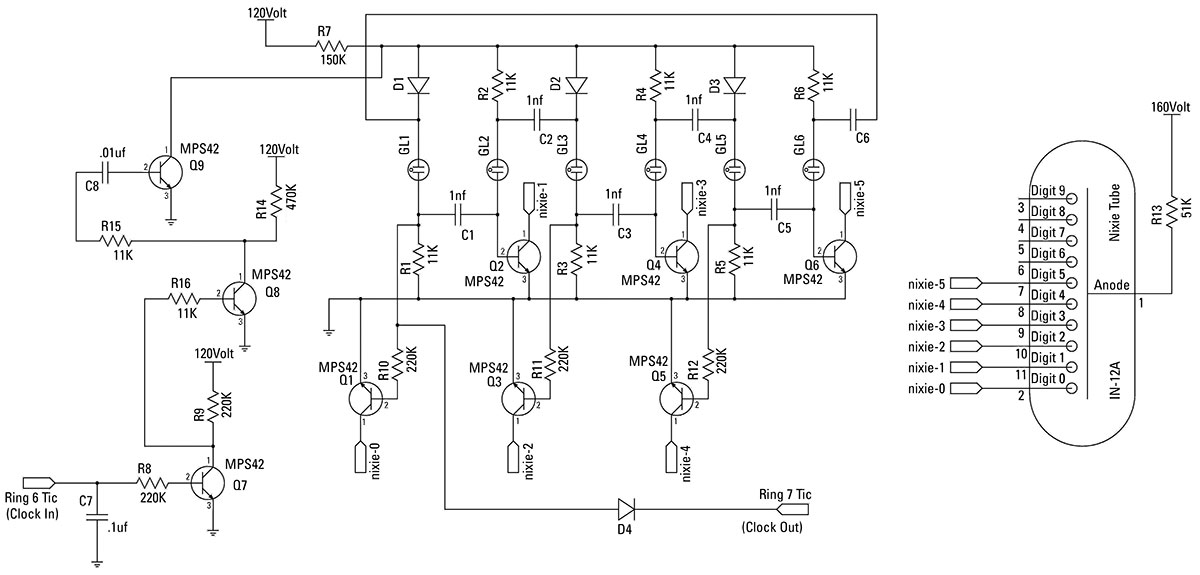
FIGURE 4. Six-stage ring counter schematic.
It depicts the more complex three-transistor trigger circuit used in the latter five rings. This trigger circuit uses the first two transistors to clean up the pulses from the previous stage which then are capacitively coupled to the third stage which is then tied directly to the ring. This provides a short clean pulse to ground with each input transition from low to high.
Figure 4 also depicts the Nixie tube drivers. For driving the Nixie tubes, three of the diodes tied to ground in the standard ring are replaced with the base-emitter junction of a transistor. When the neon lamp lights, the transistor turns on which lights the appropriate digit. This works for half of the
digits. To drive the other half of the digits, a transistor is tied to the lamp side of the resistor through a resistor. The transistor drivers are only used in the ring for the minutes and the ring for the 10s of minutes.
To indicate hours, a 12-stage ring (which is not shown) is used. This ring is similar to the divide by 10 stage adding two stages to the ring, as well as using the three-transistor trigger circuit.
Ring Counter Operation
The ring counters work by relying on the fact that the neon lamps require a higher voltage to turn on than to remain lit. Figure 3 will be used to explain the operation of the ring.
On initially powering up the ring, one (maybe more) lamp will light. We'll assume that lamp GL3 is lit. This will put a 5 to 10 volt drop across R3 which will charge C3 to the same voltage through D4. If a positive pulse is applied to “Pulse In,” a negative pulse will be applied to the ring counter which should extinguish the GL3. This will bring the voltage level on the resistor side of C3 to 0 which will force the diode side of the C3 to -5 to -10 volts.
As the voltage is re-established on the ring, lamp GL4 will light up first because it will have the additional voltage of the capacitor as an advantage over the others. Once it lights, it will draw enough current through the 150K resistor R11 to lower the voltage on the ring down below the level that any of the other lamps will be able to light. The lighting of lamp GL4 will then charge C4 and the process will continue with each pulsing of “PulseIn.”
To cascade rings, “Pulse Out” can be taken from the lamp side of any of the 11K resistors which are tied to ground. It must not be loaded too heavily by the successive stage or its operation will be effected. One important thing to remember — as far as the overall clock is considered — the stage which is used for “Pulse Out” will be 0 for that ring. This is most important for the minutes and 10s of minutes rings.
Board Construction
First, a warning! This clock uses 120 volts and 160 volts which are present throughout the board. Handle the board carefully! The corners are “ground” and the board can be held by them safely.
This board contains parts which must be installed in a certain direction.The electrolytic capacitors must have the positive lead (typically, the long lead) inserted into the hole with the square pad. There is a small plus sign by that pad, as well. Diodes must have their cathode inserted in the square hole.
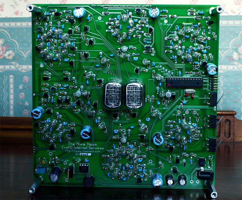
Completed circuit board.
The cathode side of the diode has a stripe painted on it. The transistors and the regulator have their outline silkscreened on the board. Be sure to orient them correctly. The markings on the bridge rectifier are faint, but they match the markings on the silkscreen of the board.
Pin 1 of the two integrated circuits has a square pad. Putting in any of the parts backwards will cause the clock to malfunction or damage to occur to the component or the clock.
I do not recommend using water soluble rosin core solder, either. My attempt at building one of these clocks with it just left me totally frustrated. The water soluble rosin is conductive and you need to wash the board, then dry it completely to test the clock as you build it. Any changes to parts of the rings involve a wash and dry cycle, as well.
For the printed circut board (PCB), the first step should be to solder in the pins for the Nixie tubes. These are small and will not stay put until they are soldered. Insert each of the pins through their hole and then place a piece of cardboard over them and turn the board upside down and solder them in on the solder side. Once they have cooled, the board can be moved freely.
Next, the power supplies should be built; first, the low voltage portion, making sure that 12 volts (may be as high as 15 or 16 volts) and five volts are made. Then, build the high voltage portion. Make sure that it generates about 160 volts. Adjust R3 until it does. About 120 volts should be present on the cathode of Z1.
Next, the miscellaneous parts which have small quantities should be installed. These include the 51K, 100K, 1M, 470K, and 220K resistors. Follow these with the 20 pf, .01 µF, .1 µF, and the 150 µF capacitors. Once these are installed, install the MPSA42 transistors and the four colored neon bulbs which are a frosted white color when unlit.
Next, install the three micro switches, the socket for the CPU, 16 MHz crystal, two 1K resistors, and the J2 header. DO NOT INSTALL THE PROCESSOR YET.
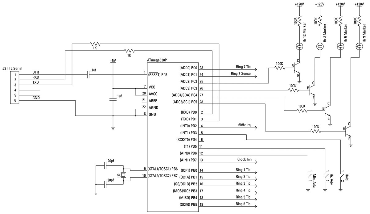
CPU diagram.
Now, we start work on building the ring counters themselves. One at a time starting with the bottom center ring counter, work your way around the board clockwise. We need to test each ring before moving to the next.
In an ideal world, the neon bulbs would have identical firing voltages. Sadly, they do not. After building a number of these clocks, I have found that most of them will only have one or two bulbs which don’t want to work right. Other clocks have had five or six lamps misbehave.
Typically, the first two rings work when built. For the rings after the first two, I recommend they be breadboarded first using a protoboard to weed out any lamps which don’t fire reliably (to be referenced as finicky from now on) or lamps which fire at a lower trigger voltage (to be referenced as erratic).
Either of these types of lamps will cause the ring to misstep.
Figure 2 can be used with the protoboard. When doing the six-stage ring counter, simply don’t populate the last four neon bulbs, and move the wire which feeds back the pulses from the last stage to the first over to stage 6.
Just above the second ring (near the switches), there are three test points: 120V, GND, and 1 sec. Solder a wire to each of these to drive the protoboard.
Typically, if there's a finicky lamp, one or more lamps will be skipped when the finicky one is supposed to light. This can be fixed by replacing the lamp which is the first not to light in the series. Erratic lamps will behave similarly except that at any point in the ring, the lamp will light and the count will pick up from there. Sadly, it's hard to distinguish the two, though I found more often than not that I should assume a finicky lamp before an erratic lamp.
Start assembling a ring by soldering in the diodes. Be sure to take note that the wire of the cathode side of the diode (the side with the line) should be inserted into the hole with the square pad. Follow the diodes with the 11K resistors. Follow these with the capacitors. The capacitor symbol is a bit hard to see; it's two lines which are broken as they pass between the two pads for the capacitor.
Install the transistors for the rings next. The fifth and sixth rings will require more transistors than the other rings.
Once the transistors are in, solder in the neon lamps. On many of my clocks, I have placed a small glass bead on each lead of the lamps to act as a standoff. Be sure to solder them in straight; otherwise, the rings won’t look right. After I solder in the lamps and check that the ring is operating properly, I straighten any bulbs by melting the solder of one leg and tilting it upright.
To test a stage, turn on the clock and verify that one or more lamps light up. It should be easy to determine if the first three rings are operating. After this, the sequencing is slow enough to make it harder to tell.
To speed this up, connect a wire between the 1 sec test point to the test point feeding the ring in question. This should cycle the ring at 1 Hz.
For the minutes and 10s of minutes stages, you can install the appropriate Nixie tube for the stage and verify that all of the digits work as you expect. In both of the rings, the neon bulbs have the number of the digit they are associated with printed on the silkscreen. Unplug the adapter and move to the next stage until all of the stages are complete.
Clock Operation
On power-up, the clock will reset itself to 01:00:00. Reading the clock is fairly straightforward. The minutes are displayed on the two digits, while the hours are displayed by the circle of 12 neon bulbs encircling the digits.
The time can be set by pressing the Min Adv or Hour Adv buttons. When either of these buttons are first pressed, the clock will sequence to the time it has saved in its memory. Once it has set the time, pressing and holding either the Min Adv or Hour Adv button will advance the minutes or the hours, respectively. You can go back and forth between the two switches setting the minutes and hours as needed. The clock will hold its time until the Pause button is pressed and released.
The rings can be run at an accelerated rate. This is useful for forcing rings to miscount. By pressing the Hold button and the Hour Adv button simultaneously, the processor will take over and run the first ring. It will only be at a slightly different speed than normal. Pressing the Min Adv button will cause the processor to move to the next ring. Subsequent presses of the Min Adv button will cause the processor to sequence each ring. Pressing and releasing the Hold button will cause the clock to set itself to the current time, then resume normal operation.
A note of caution! When you go to touch the clock, you should try to discharge yourself first. I haven’t damaged a clock with a static zap, but I have made them display some interesting times on their rings.
Software
The source code as well as instructions for building the clock are available in the article downloads or can also be found at www.nixieneon.com. The software for the board is released under the GNU GPL license. It can be downloaded using the program avrdude from https://www.nongnu.org/avrdude/ or by using WinAvr which can be found at http://sourceforge.net/projects/winavr/. WinAvr is a complete development system.
The clock can be communicated with using the TTL level serial port on J2. The pinout for this header matches the FTDI USB-to-serial converter board sold at www.sparkfun.com. Be sure to get the five volt version. The following commands are available through the serial port. Each command should be typed in, followed by the enter key. Any subsequent input needed will be prompted for.
razzle: Makes the rings dance.
reset: Resets the time to 01:00:00.
seqtime: Sets the speed to run the rings in the diagnostic mode.
settime: Sets the time.
step: Steps individual rings for diagnostics.
sync: Runs the rings to set the clock to its current time.
synctime: Sets the time interval in seconds; the clock will reset its time.
Wrap Up
I believe that I have come up with an intriguing clock design which can provide hours of enjoyment and satisfaction both in its construction, as well as watching it work once it is complete. With over 400 parts, it should prove to be a good challenge for anyone, with the reward of having a very unique Nixie clocks.
As a benefit, if the builder doesn’t have much time soldering under their belt, they will by the time this clock is complete! NV
PARTS LIST
| 1 |
IC Socket 28-pin |
(Mouser #: 571-1-390261-9; www.mouser.com) |
| 1 |
HC-49/S Crystal - 16 MHz 20 pF |
(Mouser #: 73-XT49S1600-20) |
| 3 |
Fuses - Axial Lead, 125V .5A |
(Mouser #: 576-0251.500MXL) |
| 2 |
1/8W 5% Carbon Film Resistors - 1.0K ohms |
(Mouser #: 299-1K-RC) |
| 1 |
1/8W 5% Carbon Film Resistor - 1.2K ohms |
(Mouser #: 299-1.2K-RC) |
| 1 |
1/8W 5% Carbon Film Resistor - 2.2K ohms |
(Mouser #: 299-2.2K-RC) |
| 4 |
1/8W 5% Carbon Film Resistors - 51K ohms |
(Mouser #: 299-51K-RC)10 |
| 10 |
1/8W 5% Carbon Film Resistors - 100K ohms |
(Mouser #: 299-100K-RC) |
| 6 |
1/8W 5% Carbon Film Resistors - 1M ohms |
(Mouser #: 299-1M-RC) |
| 5 |
1/8W 5% Carbon Film Resistors - 470K ohms |
(Mouser #: 299-470K-RC) |
| 7 |
1/8W 5% Carbon Film Resistors - 150K ohms |
(Mouser #: 299-150K-RC) |
| 22 |
1/8W 5% Carbon Film Resistors - 220K ohms |
(Mouser #: 299-220K-RC) |
| 80 |
1/8W 1% Metal Film Resistors - 11K ohms 50 PPM |
(Mouser #: 270-11K-RC) |
| 1 |
1/2W 5% Resistor - .1 ohms |
(Mouser #: 660-SPRX1/2CT52RR10J) |
| 1 |
Multi-Turn Potentiometer - 20K ohms |
(Mouser #: 81-PV36W203C01B00) |
| 2 |
Ceramic Disc Capacitors - 20 pF 50V |
(Mouser #: 140-50N2-200J-RC) |
| 11 |
Capacitors - 0.1 µF 50 volts |
(Mouser #: 81-RPEE41H104M2K1A03) |
| 1 |
Capacitor - 2200 pF 200 volts |
(Mouser #: 80-C320C222J) |
| 61 |
Capacitors - 1,000 pF 50 volts |
(Mouser #: 81-RPER71102K2P1A03B) |
| 5 |
Capacitors - 0.01 µF 50 volts |
(Mouser #: 81-RPEE41103M2K1A03B) |
| 1 |
Electrolytic Capacitors - 10 µF 250 volts |
(Mouser #: 75-515D106M250CG6A) |
| 7 |
Electrolytic Capacitors - 10 µF 160V |
(Mouser #: 140-XRL160V10-RC) |
| 2 |
Low ESR Electrolytic Capacitors - 100 µF 25 volts |
(Mouser #: 140-ESRL25V100-RC) |
| 1 |
Inductors Radial Lead - 220 UH |
(Mouser # 580-18R224C) |
| 70 |
Neon Base Wire Terminal - 65 VAC .7 mA NE-2E |
(Mouser #: 606-A9A) |
| 1 |
Rectifier - Bridge 1A 50V |
(Mouser #: 583-DB101) |
| 3 |
Snap-Action Switches - 50 MA Insert Left |
(Mouser #: 540-DG23-B3LA) |
| 1 |
DC Power Jack PCB 2.1 MM |
(Mouser #: 163-179PH-EX) |
| 1 |
Fast Recovery Rectifier - 1.0A 400V |
(Mouser #: 625-1N4936-E3) |
| 67 |
Diodes 1SS244 - 200 MA 250V |
(Mouser #: 755-1SS244T-77) |
| 1 |
Zener 1N5380 - 120V 5W |
(Mouser #: 863-1N5380BG) |
| 1 |
IRF830 MOSFET Transistor N-Chan 500V 5.0A |
(Mouser #: 844-IRF830APBF) |
| 1 |
LM78L05 Linear Regulator 0.1A Pos Volt Reg |
(Mouser #: 512-LM78L05ACZ) |
| 38 |
MPSA42 Transistors NPN High Voltage Transistor |
(Mouser #: 512-MPSA42_J18Z) |
| 24 |
Socket Receptacles |
(Mouser #: 575-032700) |
| 4 |
Spacers and Standoffs HEX .250x.500 Alum |
(Mouser #: 534-2210) |
| 4 |
Spacers and Standoffs AL 1.500 M/F Thrd |
(Mouser #: 534-8422) |
| 1 |
AC Adapter - 12 VAC 500 MA 2.1 MM |
(Mouser #: 412-212054) |
| 2 |
IN-12a Nixie Tubes |
(www.AllSpectrum.com #IN-12A) |
| 4 |
Green or Blue 15 mm Neon Bulbs |
(All Spectrum #NE-2B-6x15x30) |
| 1 |
Maxim 1771 Power Supply IC |
(All Spectrum #MAX1771) |
| 1 |
ATmega 328P Processor with Arduino Bootloader |
(www.sparkfun.com #DEV-09217) |
| |
Optional but recommended: |
|
| 1 |
Solderless Breadboard 630 + 200 Tie Points |
(Mouser #589-TW-E40-1020) |
| 1 |
USB to 5V serial converter |
(SparkFun #DEV-09115) |
Note to readers: Keep in mind this article first appeared in our August 2009 issue. Some parts may be obsolete and will need to be substituted. We've left the original part numbers and sources that were given at the time of publication listed in case they can be of assistance. There is a complete kit available in our store for purchase.
Downloads
What’s in the zip?
Source code
Kit manual