Hard-wiring is always a problem, especially with an old house. With the new Linx transmitters and transceivers, this can be done wirelessly. The cost of the project is less than $65 + boards. Pre-programmed chips and boards are available in the Nuts & Volts Webstore.
 The primary design shown here was made for a single garage door. Installation is simple. Using Velcro tape, the transmitter is placed on the back of one of the panels of the door, and the receiver is in the bedroom. When the door goes up or down, the receiver indicates its position. There’s no wiring of switches as it uses an internal tilt switch.
If you have more than one garage door, the transmitter can be hard-wired for up to three doors using magnetic switches; it will indicate each door’s position. A single receiver receives and decodes three garage doors, and they don’t have to be in the same location. The transmitter and the receiver use two AAA batteries which should last six months to a year. Both the transmitter and receiver have an audio indicator to let you know when the batteries need replacing.
 The receiver also has a switch that can be activated to be an alarm if any of the doors are opened by a burglar. See Figure 1.
Electronics
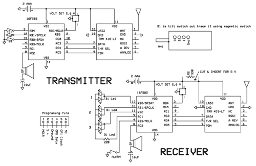
In both the transmitter and receiver are two ICs, a Linx transceiver, and Microchip PIC16F505 which directs the transceiver. A voltage detector is used to determine if the batteries are getting low.
The transmitter is put to sleep to save power. It draws 12 micro-amps when sleeping. The transmitter activates every 2.3 seconds by use of a watch dog timer (WDT). When the WDT times out, the unit checks the battery voltage. If the voltage drops below 2.4 volts, it beeps. The transducer resonates at 2.730 kHz. The micro proves a square wave at this frequency; the 10 µF capacitor blocks DC but allows the AC to pass.
If the tilt switch or any of the magnetic switches activate, it transmits a code to the receiver. The code is 16 bits wide and the first three lower bits determine which door is open. This leaves 13 bits for scrambling 132 = 8,192 combinations. The transmitter turns on the Linx transceiver and sends the codes. It transmits for about five seconds and goes back to sleep. The code combination flow sheet is located on the NV website.
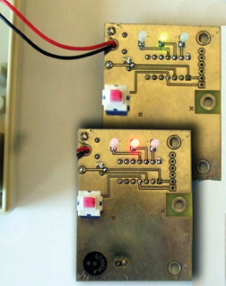 The receiver basically has the same parts but uses three bi-colored LEDs to indicate door positions. See Figure 2. It also wakes up every 2.3 seconds and looks for a valid transmit signal and code for 20 microseconds. If there is none, it goes back to sleep. It counts four 2.3 cycles and then flashes either green or red indicating the door positions. If it receives a signal from the transmitter, it changes its display and will flash the LEDs until the transmitter stops its transmission.
Both micros control the transceiver’s power using the PDN line control. The T/R SEL pin differentiates between sent data and received data.
Construction
Boxes
Go to the downloads link indicated here and download Garage Door Download. There are templates included in the attached files. Print and cut them out. With the two halves together, turn the box over and locate the battery holder area. Place the battery area towards you and turn the box face up. 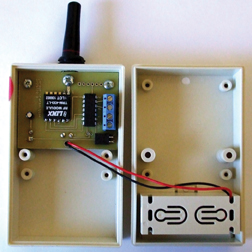 The board and antenna go on the far end as shown in Figure 3. (The box will not go together if the top half is reversed). Using a glue stick, glue the antenna template, front panel template, and side templates to the box. Using a drill press, drill the proper size holes as indicated on the templates. The receiver box is done the same way, however, there are no side holes; only the front panel and antenna. After the holes are drilled, use hot water to remove the templates and glue.
Transmitter
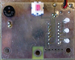
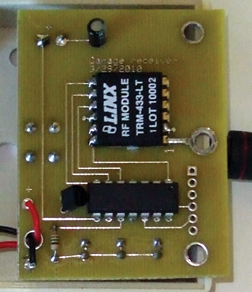
On the top of the board, mount the Linx module first, then the microprocessor, capacitor, terminals, and the voltage detector. The tilt switch is mounted on its side with its terminals toward the edge of the board. 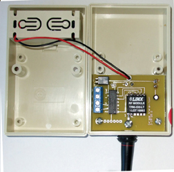 The transducer is mounted on the bottom of the board. Look at Figure 4. Note the polarities on the components which require them. Thread the wires from the battery holder through the slots of the battery compartment, through the antenna, and place it through its hole. Add the board over the antenna and secure with a screw. Use two self-tapping screws to secure the board to the box.
 Receiver
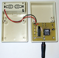
On the top of the board, mount the Linx module first, then the microprocessor, capacitor, resistor, and the voltage detector. Add the transducer, LEDs, and the switch on the bottom side. The best way to insure the correct length of the LEDs is to place them in the board, place the board in the box, seat them in their holes, and solder the leads. Take a look at Figure 5. As above, solder the battery holder wires and install the antenna.
Testing
There are no off or on switches on either box. Once the batteries are installed, they are active. Turn the transmitter box on its side so that its antenna is pointing to the left; observe the receiver. Now turn the box so that it is on its back or front. The receiver light should change. (See the demo video in the NV downloads.)
Mounting
The transmitter should be mounted with the antenna horizontal and pointing left. If there is only one garage door, it can be mounted with double-backed Velcro tape. As the door tips activating the tilt switch, the transmitter will transmit. If you have more than one garage door (up to three), you can use a magnetic switch on the doors and connect them to the three terminals in the box. (Check out Digi-Key CKN6004-ND.) Terminal one is common ground. Cut the trace coming from the tilt indicator. Again, mount the box with the antenna horizontal.
The receiver should be placed on either side with the antenna also horizontal. If the switch is pressed, the unit will act as an alarm if the doors are open.
 Software
The program files are also located on the NV website. It is best to download MPLAB IDE from [url=http://www.microchip.com]http://www.microchip.com[/url] to program or make modifications. They are labeled Garage Transmitter.asm and Garage Receiver.asm. See Figure 6 for the flowchart.
Programming
You will need a PIC II programmer for programming. The chip used is a PIC16F505 which can be programmed from the board. I use programming pads instead of pins. I developed an adapter using Mill Max spring-loaded pins.
You can solder a header to the programming pads if you wish. When programming, make sure that the receiver alarm switch is open. With the transmitter, make sure that there are no wires in the terminals and the tilt switch is parallel to the floor.
Two keys are used for the combination; Key 1 has eight bits and Key 2 has five bits. The combination codes are placed in line 81 and line 85. Both the transmitter and the receiver must have the same code to function. The input pins to the tilt switch and other switches (if used) are programmed to use the micro’s internal pull-up resistors. They are programmed to wake up the micro if there is a pin change. The micro determines if the wake-up was caused by a WDT or pin change using line 107.
Once the unit is awakened by a pin change, the switch results are placed in the first three bits of Key 2. The transceiver is turned on to transmit, and 16 bits of information are sent out using bit-banging 1200 baud. It transmits for about five seconds and then goes back to sleep.
To overcome any noise or random signals in the Linx module, I just made sure that the transmission is high (indicating a true signal) for a period of time and then check to see if there is a start signal sent.
Once this happens, the receiver gets the 16 bits of code and checks the code against its combination. If this matches, it decodes the first three bits of Key 2 and transfers this information to be displayed.
The display uses three bi-colored LEDs which are multiplexed. Each is flashed for a few milli-seconds. Their cathodes are tied together; reversing the pins from Vss to Vpp will determine what their color will be depending on their input pin. (See Figure 7.)
Voltage detection is accomplished using a Microchip voltage detector with a 2.4 volt open drain. This is connected to an input pin which has an internal pull-up pin. When the voltage drops below 2.4 volts, it pulls this pin to ground. The WDT checks this every 2.3 seconds. If the voltage is low, the program jumps to the speaker program. This code produces a 2.7 kHz square wave for 100 milli-seconds (thus giving more of a click to save power), indicating that the battery needs changing.
Using More Than One Transmitter
If you are going to use more than one transmitter, make sure all the transmitters have the same combination.
Go to lines 62, 63, and 64, and swap S1 or S2 with Tilt, e.g., put Tilt in place of S1 (62) and move S1 to the Tilt (64). Now the receiver will read the new transmitter as S1. If you have trouble locating parts, there is a parts source on the website. In upcoming months, watch for hacks for this project posted in the feature article section on the Nuts & Volts website. Happy transmission! NV
Corrections
The templates have been revised for proper location of the switch and speaker on the receiver.
The software was revised for better power savings.* Revision D.
For the antennas to fit properly, file out the clear area on the boards where the antenna mounts.
I have some complaints about battery life on the receiver. The calculated time is about 83 days on a set of AAA batteries. I use Digikey T977-P6P-ND battery eliminator that sells for $6.09. It increases the alarm volume.
Downloads
Garage Door Alarm Schematic
Schematics for transmitter and receiver units in PDF format.
Garage Door Alarm Parts List
Parts List in Excel format with links to suppliers for parts.
Flow Charts in PDF format for operation of both the transmitter and receiver.
All files for the garage door open alarm.