I have always had an interest in astronomy and bought my Celestron telescope in 1978. However, living in Michigan I was plagued by mosquito-filled summer evenings and frozen winter nights, so I began looking for ways to do my observing indoors at my convenience. I have also always been interested in the mathematics behind the motion of the planets, which have been known since the 17th century when Johannes Kepler published his Astronomia Nova which allowed the accurate calculation of planetary locations in the sky. In 1978, Jean Meeus first published Astronomical Formulae for Calculators which allowed these calculations to be performed on the programmable calculators of the day. Using these formulae, I can calculate the location of celestial objects using a microprocessor.
Yet another interest of mine is in steampunk technology and clocks. Thus was born my concept of a steampunk clock that would utilize a small LCD display to show the time in several formats — one of which is a planetarium view of the sky from my home in Las Cruces, NM. The planetarium part was the most interesting and complex, so that is where I’ll start.
Getting Started
I saw an article in Nuts & Volts (April 2012 by Thomas Kibalo) that featured a product from 4D Systems in Sydney, Australia. I did quite a bit of research on their products and support before choosing the uLCD-32PT LCD display with integrated touch. It features a 320x240 QVGA display with 65K color depth per pixel. It also features 15K of program Flash memory, 14K of RAM, and a microSD card on the display board. A program in Flash can load programs from the microSD card into RAM, and execute them from there. The display is powered by their PICASO-GFX2 processor that features "soft silicon." It can be programmed to act as a stand-alone processor in GFX mode, or as a serial graphics display in SGC mode.
My original plan was to simply do all of the mathematics in the GFX mode, then display the stars, sun, moon, and five classical planets on the display. I soon realized that 15K of memory would be a serious limitation. The calculation of the positions of the sun, moon, and planets requires at least nine digits of accuracy to get even close to their true positions in the sky. Since the GFX language only supports integer math, this was going to be difficult.
Then, I remembered a product from Micromega Corporation in Kingston, Ontario. I had purchased one of their uM-FPU V3.1 floating point math coprocessor chips several years ago. The uM-FPU can offload the math calculations from a microcontroller. It worked great, but since it only supported 32-bit floating point, it was limited to seven digits of precision. This past year, they announced their new uM-FPU64 chip with support for 64-bit floating point. Here was the answer to my problems.
The uM-FPU64 provides 15 digits of precision which would allow me to accurately perform the astronomical calculations. The bonus was that the uM-FPU64 has a built-in real time clock (RTC). It can be connected with either an SPI or I2C interface. I was quite familiar with the I2C interface from previous work with the Atmel ATmega, and it was also supported by the uLCD-32PT, so I was now ready to proceed with my project.
Putting the Pieces Together
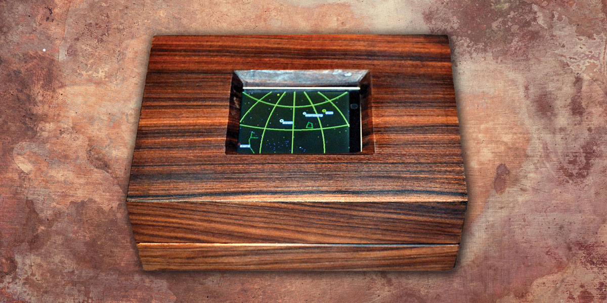
My objective for the steampunk clock was to have an attractive enclosure suitable for display in the living areas of my home, but any project box would work just fine. Figure 1 (at top) shows the 5" x 7" x 2.5" box made from Bolivian rosewood that I had a local woodworker build. The uLCD-32PT is mounted on a carrier board with four tabs to hold it in place.
I purchased the 4D Systems expansion board which provides a convenient breakout of the two headers on the display board to a series of 0.1" headers that are easy to access. I also purchased their USB programming cable which allowed me to upload and debug programs to either RAM or Flash memory.
The GFX programming language is very "C like," so was easy for me to learn. The programming cable also provides 5V for powering the board ... I highly recommend this. The expansion board allows access to the I2C SDA and SCL signals and provides pull-up resistors. If you choose not to use the expansion board, remember to add pull-up resistors for the SDA and SCL signals.
The expansion board also provides access to 400 mA of 3.3V regulated DC, which is just what the doctor ordered for powering the uM-FPU64.
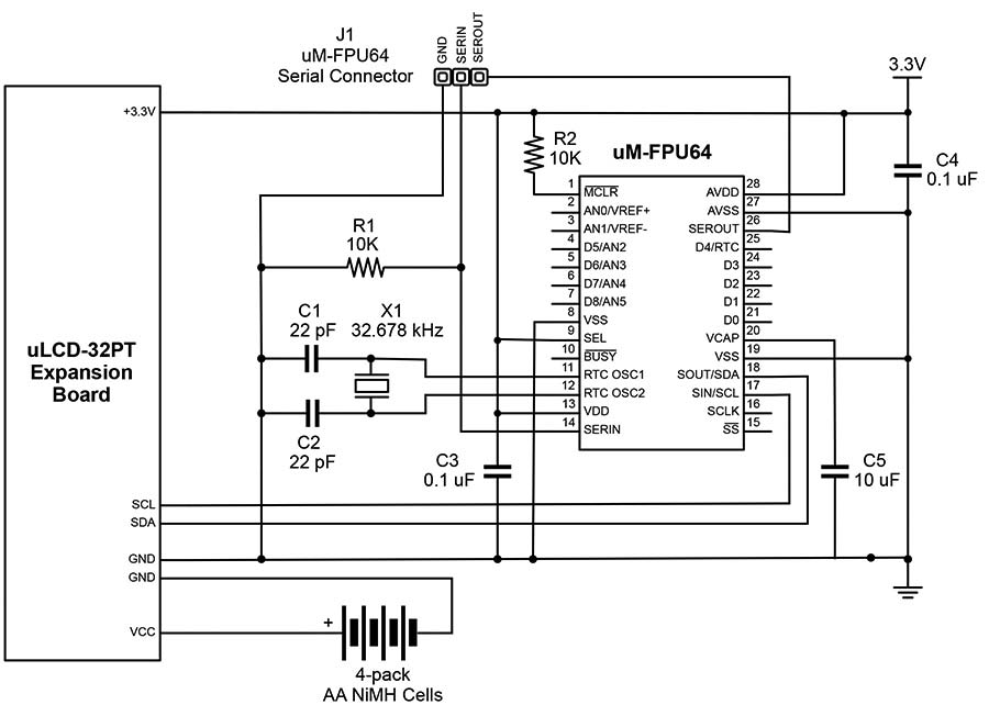
FIGURE 2. Circuit diagram for the uLCD-32PT expansion board and uM-FPU64 connections.
Figure 2 shows the schematic diagram of the circuit and Figure 3 shows a view of everything connected. I used a printed circuit board (PCB) to mount the uM-FPU64 and a standard 32 kHz clock crystal for the RTC. I added header pins to provide power and to access the uM-FPU64 serial connection (for debugging) and the I2C connection.
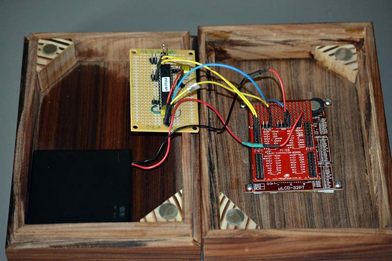
FIGURE 3. The completed electronics mounted in the enclosure.
The documentation provided by both 4D Systems and Micromega is exceptionally clear. In addition, there are excellent forums and support available for both products. (The 4D Systems people in Australia never sleep!)
Finally, power is required when not using the USB programming cable, so a simple four pack of AA NiMH cells makes the entire unit portable with about six hours of run time.
Software
The remainder of the project involved software development, which took a couple of months of on and off work. It was very interesting and always challenging. The uLCD-32PT acts as the I2C master, sending commands to the uM-FPU64 and receiving the results of the calculations.
Early on, a decision had to be made as to how much information to display. Realistically, one does not want to try and display the entire visible sky because a lot of distortion would occur. I chose to show the view from Las Cruces looking south and ± 60 degrees to either side with a vertical range of +80 from the horizon. A series of calculations start from the current date and time.
At initial power-up, the date is loaded into the RTC using a simple keypad on the touch display as shown in Figure 4. After the initial setup, the current date and time is maintained by the RTC. Note that I chose to only work with dates from 2000 to 2099.
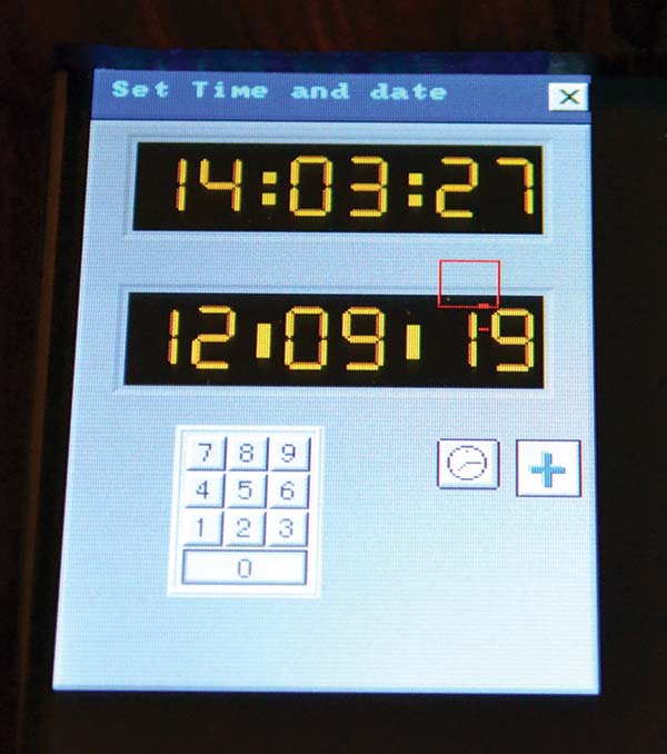
FIGURE 4. Setting the initial date and time values.
The mathematics will accommodate dates and times from ~4000 BC to 3000 AD, so you could easily extend it if you wanted to see the sky as the Spanish missionaries saw it from Las Cruces in the 1600s.
The JulianDate function stored on the uM-FPU64 calculates the Julian Date at 0 hrs Greenwich Mean Time (GMT). GMT is used to avoid the vagaries of daylight savings time. From there, a second function is used to calculate T, the time in centuries since Jan 1, 1900 — a value that is used in many of the following calculations.
The uM-FPU64 has 4 KB of Flash memory to store your functions. I used the same programming cable from the uLCD-32PT to program and debug the uM-FPU64 functions. A third function calculates the sidereal time at Greenwich at 0 hrs GMT. Sidereal time reflects the fact that the earth's revolution on its axis does not correspond with the same view of the sky at the same time each day.
This results in the progression of the constellations that are visible in the different seasons of the year. Orion, for example, is a nighttime constellation during the winter in the northern hemisphere, but is not visible in the evening sky in the summer.
The STatGact and STatLC functions calculate the current sidereal time at Greenwich and then at Las Cruces, NM. The latitude and longitude of Las Cruces are stored in the uM-FPU64 Flash memory, but future modification could allow for those to be entered using the touch display, or even read automatically from a GPS receiver.
It is easy to change the longitude and latitude constants to your own location or any other location on earth. Note that for ease of calculations, most constants are stored in radians rather than degrees, minutes, and seconds.
The real work is done in the AltAz function where the altitude and azimuth are calculated. The altitude and azimuth give the location on the display, as well as the direction you should look to see the object of interest.
In order to calculate which stars are visible, their right ascensions and declinations must be known. I decided to use the microSD card to store that information. A quick search found the HYG database which is a compilation of stellar data from a variety of catalogs, and contains star names, positions, brightnesses, distances, and spectrum information. I used a spreadsheet program to narrow this extensive listing down to the 500 brightest stars and eliminated everything except the star name, right ascension, declination, magnitude, and color. The spreadsheet also converted all degrees to radians for ease of use in the astronomical calculations performed by the uM-FPU64.
I stored this list as a text file on the microSD, which is read and parsed by the uLCD-32PT program. The corresponding data for each object is sent to the uM-FPU64 and the display coordinates are returned. There are some additional mathematics that correct for the projection of a sphere onto a planar display, and I set aside some codes in the color field to be used to draw constellation lines if you wish to.
Once the screen coordinates and magnitude are returned to the uLCD-32PT program, a decision is made regarding visibility on the display. If an object is visible, it is plotted with the correct color and some adjustment in diameter based on the magnitude. The file is read and each star is plotted as it is read, until the end of the file is reached. Once the stars are displayed, additional functions are called to calculate the right ascension and declination of the sun, moon, and other classical planets. The calculations for the moon are very intense. According to Jean Meeus, "In order to calculate an accurate position of the moon, it is necessary to take into account hundreds of periodic terms in the moon's longitude, latitude, and parallax."
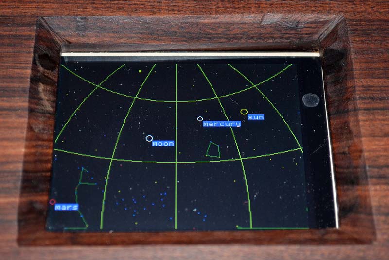
I decided to include only some major perturbations, and sacrifice some accuracy. See the sidebar for some sample uM-FPU64 code. The function to calculate altitude and azimuth screen coordinates is again called for each planetary object and the object is plotted if visible. Labels are also shown for the planetary objects. Finally, a set of 30 degree spaced coordinate altitude and azimuth lines are plotted on the screen for reference. Figure 5 shows a picture of the LCD screen with the planetarium view.
Wrapping Up
This project turned out to be very successful and very rewarding. Additional plans include putting more constellation lines onto the microSD card which is a simple process and does not require anything more than adding lines to the spreadsheet containing the star data.
Some changes to extend the battery life could be made. Turning off the graphics display and putting the uM-FPU64 into sleep mode would lengthen battery life.
A backup battery for the uM-FPU64 would allow the RTC to keep time while the main battery is removed for charging. You can certainly customize your own Steampunk planetarium clock so you can gaze at whatever stars your heart desires. NV
Special thanks to Cam Thompson at Micromega Corporation, for the impetus to write this up and critical edits.
Sample Code
This code sample shows part of the calculations for determining the position of the moon. It gives you an idea of the many astronomical calculations that are being performed on the uM-FPU64. Full code files are available for download at the article link.
; calculate the geocentric longitude of the moon
;-----------------------------------------------
MoonGeoCentLong = MeanLMoon + 6.28875*SIN(MeanAnomMoon)
+ 1.274018*SIN(2*MoonMeanElong-MeanAnomMoon)
MoonGeoCentLong = MoonGeoCentLong+.658309*SIN(2*MoonMeanElong)
+ .213616*SIN(2*MeanAnomMoon)
MoonGeoCentLong = MoonGeoCentLong/360
MoonGeoCentLong = FRAC(MoonGeoCentLong)*2*PI
; calculate the geocentric latitude of the moon
;----------------------------------------------
MoonGeoCentLat = 5.128189*SIN(MeanDisMoonNode)+.280606*SIN(MeanAnomMoon+MeanDisMoonNode)
MoonGeoCentLat = RADIANS(MoonGeoCentLat + .277693*SIN(MeanAnomMoon-MeanDisMoonNode)
+ .173238*SIN(2*MoonMeanElong-
MeanDisMoonNode))
; convert to right ascension and declination
;-------------------------------------------
A = SIN(MoonGeoCentLong)*COS(OblEcliptic)-TAN(MoonGeoCentLat)*SIN(OblEcliptic)
B = COS(MoonGeoCentLong)
RA = ATAN2(A,B)
DEC = ASIN(SIN(MoonGeoCentLat)*COS(OblEcliptic)
+ COS(MoonGeoCentLat)*SIN(OblEcliptic)*SIN(MoonGeo
CentLong))
Please note that in Jean Meeus' book, all equations are in degrees, but the uM-FPU64 uses radians in all trigonometric functions, so conversion from degrees to radians is required. The uM-FPU64 includes instructions for converting between radians and degrees.
PARTS LIST
| ITEM |
SOURCE |
| uLCD-32PT(GFX) 3.2" LCD with touch |
MicroController Pros; www.microcontrollershop.com |
| P1-EB expansion board |
MicroController Pros |
| 4D programming cable |
MicroController Pros |
| uM-FPU64 floating point coprocessor |
Micromega Corporation; www.micromegacorp.com |
| Printed circuit board |
RadioShack #276-150 |
| X1 32.768 kHz crystal |
Mouser #732-C002RX32.76K-APB; www.mouser.com |
| C1, C2 22 pF ceramic capacitor |
Mouser #581-SR152A220KAR |
| C3, C4 .1 µF ceramic capacitor |
Mouser #581-SR215C104K |
| C5 10 µF tantalum capacitor |
Mouser #581-TAP106M025SCS |
| R1, R2 10K 1/8W resistor |
Mouser #291-10K-RC |
| J1 0.1" header |
Mouser #538-22-28-4301 |
| Four pack AA NiMH battery pack |
Various sources |
SOURCES
4D Systems Pty Ltd
www.4dsystems.com.au
Micromega Corporation
www.micromegacorp.com
HYG Database
www.astronexus.com/node/34
Astronomical Formulae for Calculators 4th edition
by Jean Meeus
www.willbell.com/math/index.htm
Downloads
Steampunk Planetarium Clock Code