In Part 1, we talked about how MakerPlot (www.makerplot.com) can aid in your debugging efforts as they relate to your microcontroller projects. That's a given as it can really help, but since MakerPlot is a customizable software GUI it has many more applications for your micro's project than just a debug tool. That's what will be discussed in this article.
To review a bit, MakerPlot is Windows software that plots analog and digital signals that are generated by your microcontroller; this includes many of the popular microcontrollers on the market including the Arduino, PICAXE, Propeller, Raspberry Pi, etc.
The fundamental data connection between MakerPlot and your micro is the serial port; this can be a regular RS-232 serial port if you actually still have one or a virtual comm port that’s created using a USB connection through an FTDI (or similar) chip interface. That said, you can also use MakerPlot’s TCP/IP link if you want to monitor your micro at a remote location. Of course, you’ll need some kind of Internet or LAN connection to do this. With the proliferation of Ethernet and Wi-Fi add-on boards these days, this is easily done.
So, besides a great debugging tool with versatile data connectivity, the real power of MakerPlot is in its ability to become a virtual instrument for your micro’s data. First, however, some language definitions need to be addressed.
MakerPlot Lingo
Over the years, the lexicon of analog and digital electronic hardware and firmware programming terms has evolved as the names used to describe them have changed; at the same time, they still mean the same thing.
For example, a circuit board used to be called just that — a circuit board. If you’re an Arduino user, you know it as a “shield.” It’s fundamentally the same thing, only with a different name — mainly to distinguish it solely for the Arduino class of hardware. The same goes for firmware. Listings of source code are called “sketches” in the Arduino world. “A rose, by any other name, is still a rose,” immortalized The Bard, but apparently he was never much into product differentiation. Following this reasoning, MakerPlot has a few of its own unique term definitions that we ought to get to right now to avoid any confusion later on.
In the MakerPlot world, there are three primary terminology definitions:
• Interfaces — The GUI screens you see on the PC monitor where the data plots and other graphics are displayed.
• Controls — Any of the meters, buttons, switches, or text boxes on the Interface.
• Controller — Any microcontroller, be it Arduino, Propeller, Atmel, Intel, PIC, etc.
That’s about it. Everything else in the MakerPlot space will most likely have the same terminology and meaning that you’re used to in the general electronics and software world, so that should simplify things going forward.
MakerPlot — The "Software Kit"
While we’re at it, you may be wondering why we call MakerPlot a “DIY software kit.”
Most microcontroller projects are hardware kits that you build and program. In that regard, think of MakerPlot as a software kit because like a hardware kit, MakerPlot gives you all the necessary pieces to construct your own Interface screens that consist of multiple types of meters, switches, buttons, labels, LEDs, plot areas, etc. That’s the real power behind MakerPlot because you can do whatever you like to create the kind of Interface screens that suit your application.
We’ll get into customizing MakerPlot in subsequent articles, but for now, let’s look at what comes standard with the software. Just remember that while you examine these Interfaces, in the back of your mind think of all the ways you can modify them for your own use — because you can!
Choose Your Interface
Figure 1 is what you’ll see when you launch MakerPlot from the Desktop icon. This is called the Sign On Interface. You have the choice of up to 10 Interfaces that should serve over 90 percent of your data plotting needs. Just click on any of the graphics to bring one up.
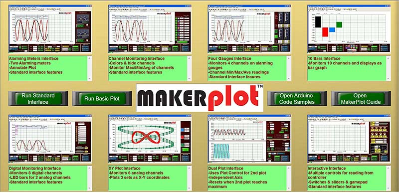
Figure 1. Sign On Interface.
There are also two important Interfaces behind the two large buttons on the left (Figure 2). These are the Basic “no frills” Interface and the Standard Interface — both of which are fundamental building blocks for the other GUI Interfaces — and fundamental to your eventual customization efforts.
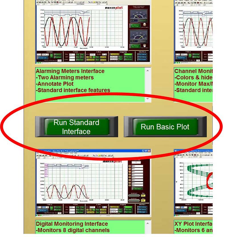
Figure 2. Interface buttons.
Figure 3 shows two other large green buttons that provide you access to the MakerPlot Guide — the major text reference manual about all things MakerPlot. Then, there’s the Arduino Code Samples button that gives you access to many useful sketches that we use to show the capabilities of MakerPlot using the Arduino series of controllers. Of course, you can modify the code to suit whatever micro you happen to be working with. So, let’s take a tour of the 10 MakerPlot Interfaces.
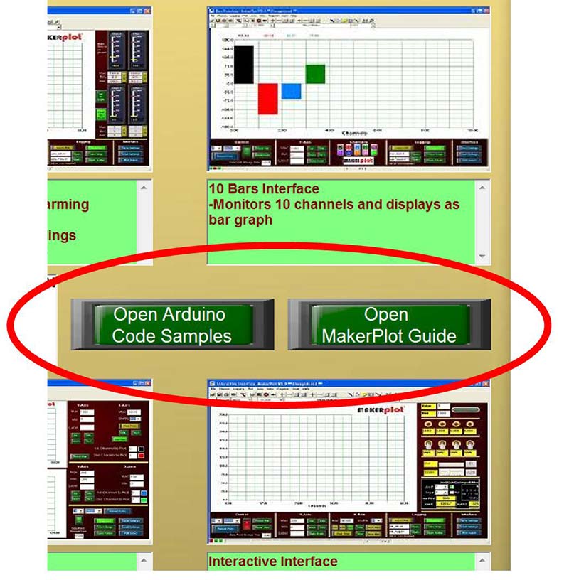
Figure 3. Arduino sketches and MakerPlot Guide buttons.
Basic "No Frills" Interface
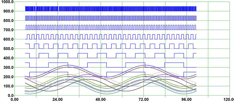
The no frills Interface is about as “basic” as it gets — a blank plotting screen with a set of toolbar icons to set up and control your plots. If you just want to get a quick glimpse of how your micro’s data is doing, this is the Interface to use.
In Figure 4, you can see both analog and digital data being plotted without any meters or switches, etc. — just a plain vanilla data plot to give you an idea of what is being output. Like a lot of things that seem simple on the surface, there is a powerful plotting tool behind this Interface.
Figure 4. Basic “no frills” plot.
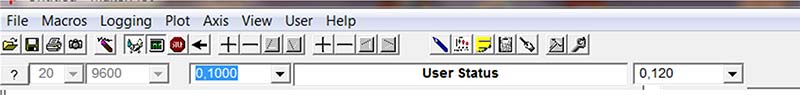
The toolbar icons — along with the top line menu (Figure 5) — form the basis for all the other Interface’s menu controls.
Figure 5. Basic plot pull-down menus and toolbar.
Here, you can set up either a serial or TCP/IP connection to your micro; change horizontal and vertical scales; switch time bases from seconds, minutes, hours, and real time; scale raw A2D (analog-to-digital) output values to their correct voltage levels without any additional micro code (just the raw A2D value); save all the data to an Excel CSV formatted file; print what’s on the screen; and lot’s more.
The Basic Interface is so extensive, in fact, that we’ve devoted an entire video series to it on our website.
Standard Interface
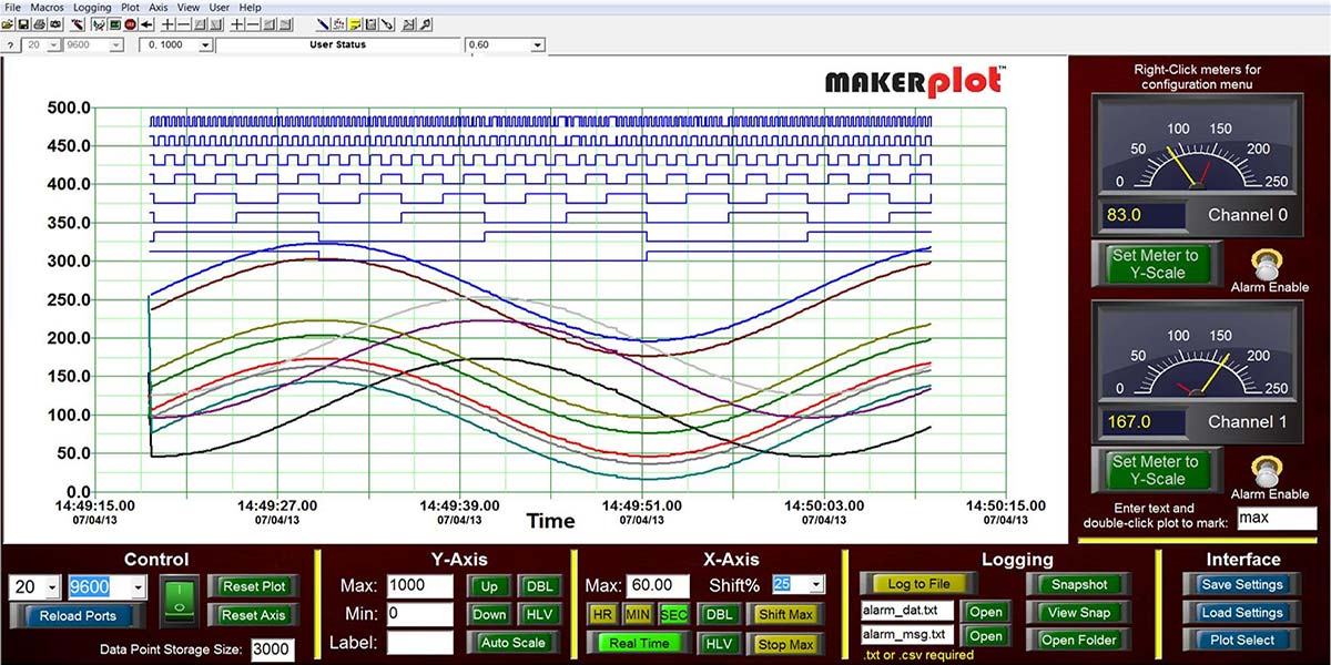
The Standard Interface (Figure 6) is where we add controls like switches, buttons, text boxes, and labels to the Basic Interface. It still has a large plot area along with a set of menu buttons, switches, and text boxes on the bottom for most of the other Interfaces we’ll discuss shortly.
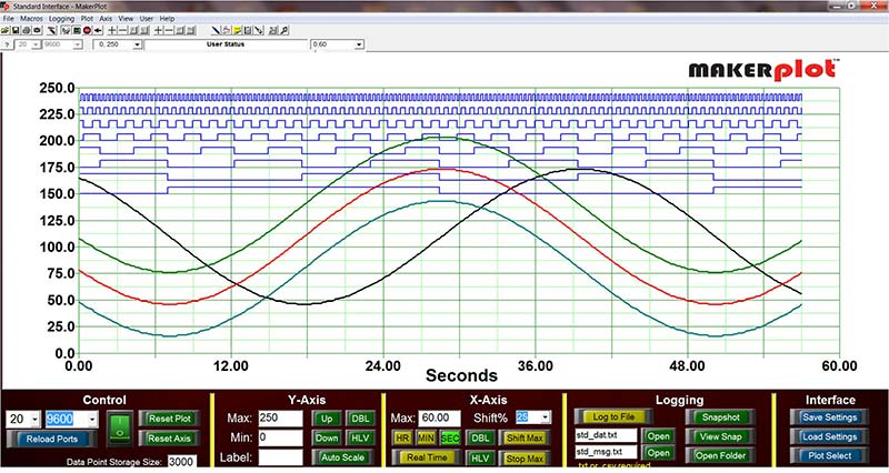
Figure 6. Standard Interface.
Control Menu (Figure 7)
• Select the comm port number to connect to your micro.
• Connect to your micro at the baud rate you select.
• Set the number of data points for plotting.
• Reset the plot.
• Reset the horizontal and vertical plot axis scales.
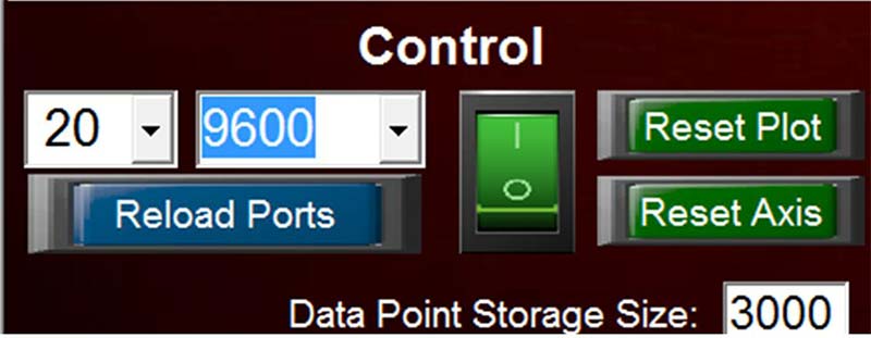
Figure 7. Control menu.
Y Axis Menu (Figure 8)
• Set the Min and Max Y scale values.
• Label the Y scale (keyboard entry).
• Shift the Y scale Up and Down.
• Double or halve the Y scale value.
• Set the Y scale amplitude to automatically adjust to your plotted data.
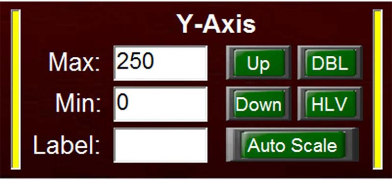
Figure 8. Y axis menu.
X Axis Menu (Figure 9)
• Set the Max time value.
• Set the plot shift percentage.
• Select Hours, Minutes, Seconds, and Real Time.
• Double or halve the time scale.
• Halt or shift the plot at Max time.
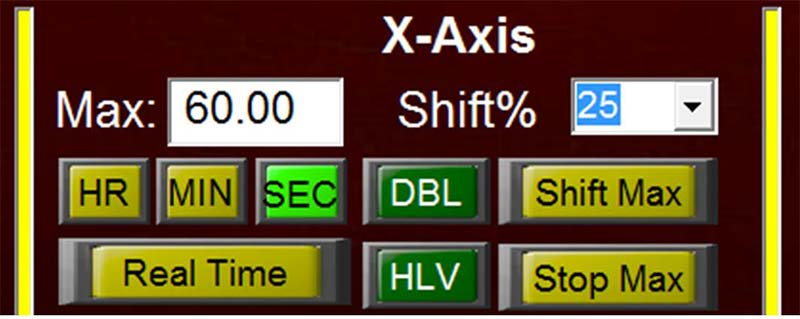
Figure 9. X axis menu.
Logging Menu (Figure 10)
• Create separate log file names for data and messages.
• Select txt or csv (Excel) file extensions.
• Start and stop data logging.
• Snap a jpg image of the screen.
• View any screen capture.
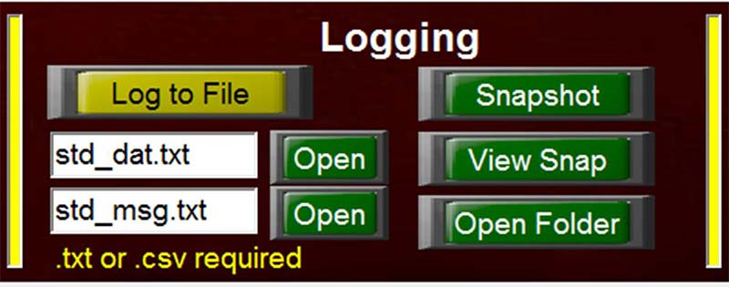
Figure 10. Logging menu.
Interface Menu (Figure 11)
• Save important parameters of this Interface for future use.
• Easily return to the Sign On Interface at the click of a button.
• The Standard Interface forms the basis for many of the other MakerPlot Interfaces (next).
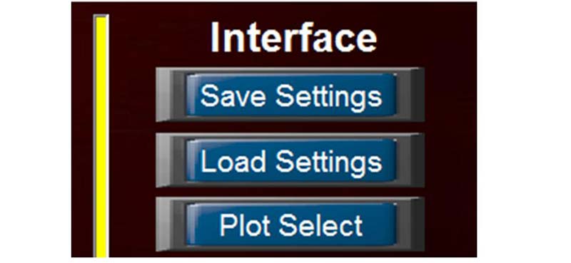
Figure 11. Interface menu.
Alarming Meters Interface
In addition to the Standard Interface menu controls, the Alarming Meters Interface (Figure 12) adds two square meters to the right side of the plot area. While analog and digital data are being plotted, you can configure these meters to select one — up to as many of — the 10 analog channels. You can also set Min and Max alarm conditions that will alert you with audio warnings (that you can also select) when conditions are above or below limits. Finally, you can click the Set Meter to Y Scale button to automatically set the meter’s full scale to the Y axis amplitude.
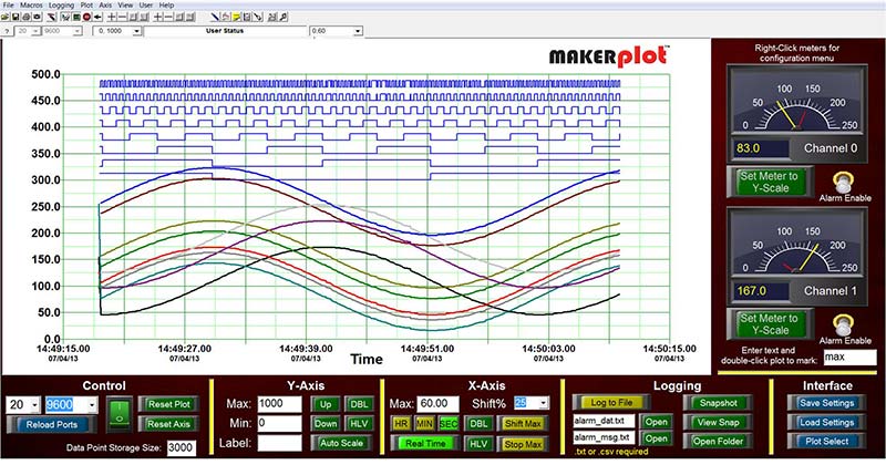
Figure 12. Alarming Meters Interface.
Channel Monitoring Interface
The Channel Monitoring Interface (Figure 13) monitors up to 10 analog channels. You can do the following for each channel:
• Turn the plotted channel data On or Off in the plot area.
• Set the color of the plotted line for that channel.
• View the value of the data in numerical form.
• Configure the value as Min, Max, Average, or Current (real time).
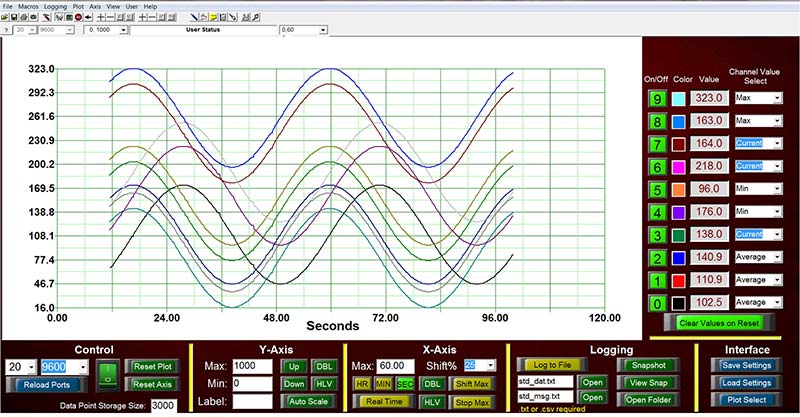
Figure 13. Channel Monitoring Interface.
So, if you want to monitor all your analog data at once, this is the Interface to use.
Four Gauges Interface
The Four Gauges Interface (Figure 14) is like the Alarming Meters Interface with two extra “vertical” meters. Here, you can monitor four analog channels at once and view the Min, Max, and Average values of each channel directly. Like the Alarming Meters Interface, you can set Min and Max alarm conditions with audio warnings, and also set the meters to the Y scale amplitude at the click of a button.
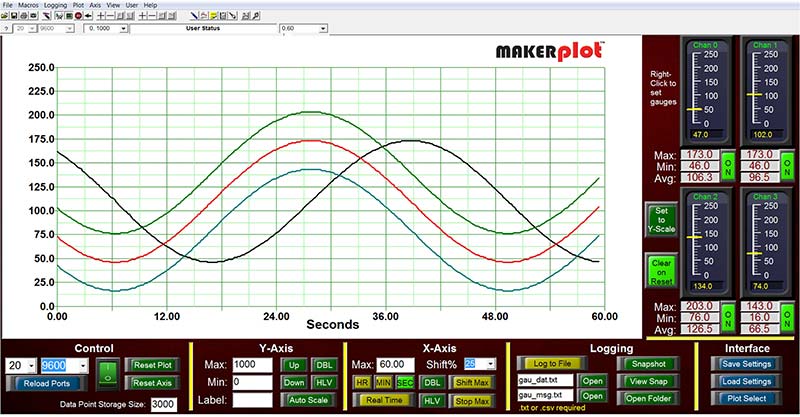
Figure 14. Four Gauges Interface.
Because you can average your analog data setting, this Interface provides the Clear On Reset button that lets you reset the average analog value for each plot across the screen. Or, when not clicked, it lets you average your analog data over long time periods.
This is a great feature when you want to know what your analog data are doing for extended periods of time.
Ten Bars Interface
The Ten Bars Interface plots up to 10 analog channels in bar graph form (Figure 15). The amplitude of each channel is displayed at the top, and you can change the color of any bar using the menu buttons below. This is just another way that MakerPlot gives you to display analog data in another form.
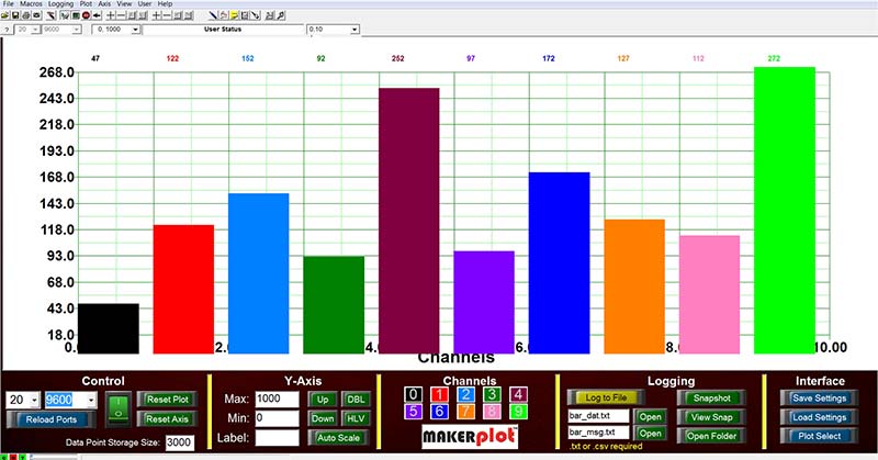
Figure 15. Ten Bars Interface.
Digital Monitoring Interface
With the Digital Monitoring Interface (Figure 16), you can plot up to eight channels of digital data and have individual LEDs flash in relation to the digital signals. You can also label each channel with text to uniquely identify it. There are two 10-segment LED indicators to monitor two channels of analog data, should you want to mix analog with digital.
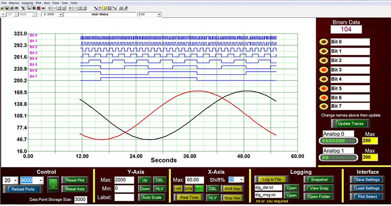
Figure 16. Digital Monitoring Interface.
X-Y Plot Interface
Instead of plotting data against time, the XY Plot Interface plots three sets of analog channel pairs (Figure 17). You can view interesting displays of data in this plotting scenario. For example, the signals that created the image shown here are all sine waves; yet, two pairs produce circles and one pair produces a line. There are lots of other interesting combinations you can generate with your data.
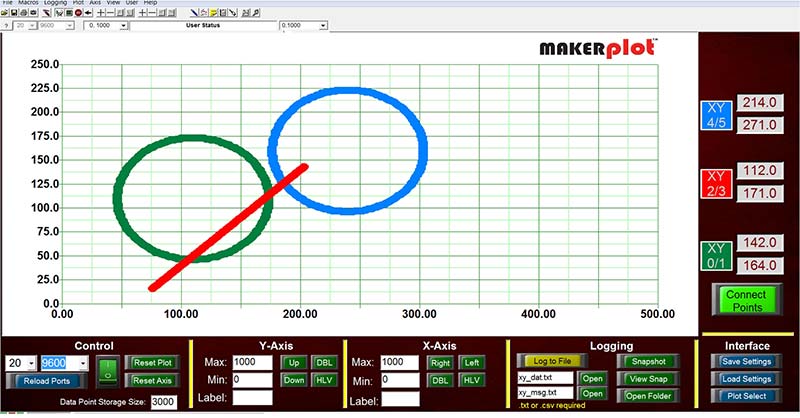
Figure 17. X-Y Plot Interface.
Dual Plot Interface
The Dual Plot Interface (Figure 18) uses two separate plot areas for plotting analog and digital data, and each plot area is independently controlled. The Dual Plot Interface is an example of how you can modify MakerPlot for your particular application. You don’t have to stick with just one plot or set of menu buttons — you can have a separate plot area for each data point.
Figure 18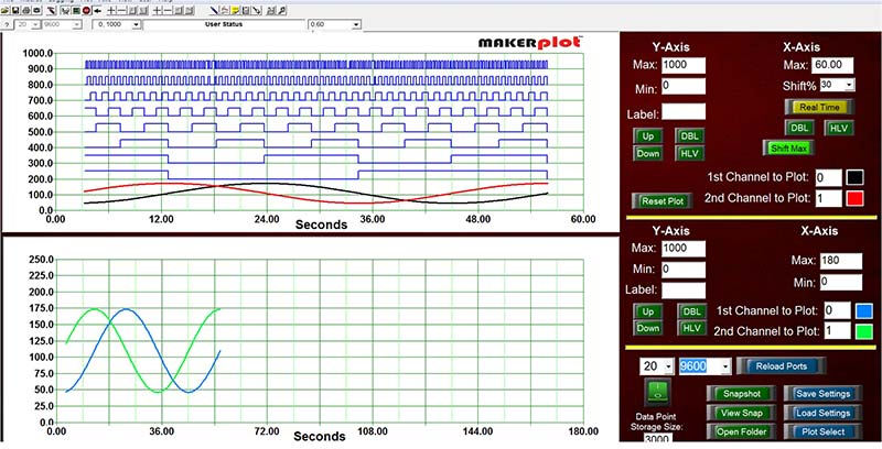 . Dual Plot Interface.
Interactive Interface
Finally, the Interactive Interface (Figure 19) is dedicated exclusively for customized, bi-directional applications that you develop for your micro. You can think of this interface as a “front panel” for your micro with switches and LEDs, along with a slider and dual joystick control. We’ll get more into bi-directional control later.
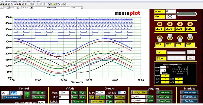
Figure 19. Interactive Interface.
Conclusion
This has been mainly a review of the off-the-shelf MakerPlot Interfaces, and it’s meant to give you a brief insight into what’s available to you for your plotting activity. To get a more complete look at how all the Interfaces perform, be sure to visit the Interfaces Videos menu link on the MakerPlot website as mentioned earlier.
In the next article, we’ll get into how to connect your PC to MakerPlot, and then go on to show how to plot analog and digital data using the Interfaces you just read about. You’ll also learn how MakerPlot can automatically scale raw A2D values to appropriate voltage levels without any coding on the micro side. This is a great feature since scaling raw A2D values does involve some degree of firmware math processing to convert from pure binary values to voltage levels.
We’ll show you how your micro can output messages to MakerPlot so that you can detect when internal events happen.
That’s all for now so just remember: Got data? MakerPlot it! NV
MakerPlot is available as a FREE 30 day trial download from www.makerplot.com. If you like what you see and what it does, you can order it through the NV Webstore at a discounted price!