In our last episode, we continued learning about Fritzing — a novice-friendly electronics hardware design package that we are using to design a real time clock (RTC) shield for an Arduino. We saw how to use Fritzing to take the breadboard design from Part 1 and turn it into a schematic drawing that is crucial for understanding and documenting a design. We also saw how to take that schematic and create a printed circuit board (PCB) design that we sent off to BatchPCB. Well, after three weeks the PCB arrived and it works! Let’s take a look at it and then go a bit further with Fritzing to start learning how to make parts.
THE PCB FINALLY ARRIVES!
Figures 1, 2, and 3 show the Fritzing breadboard, the schematic, and the PCB views, respectively, that were used to generate the Gerber files that I sent to BatchPCB. I purchased one PCB for $26.27 and received it three weeks later (really not bad at all). Plus, they sent me an extra board for free — a two for one hidden sale that you might (or might not) get!
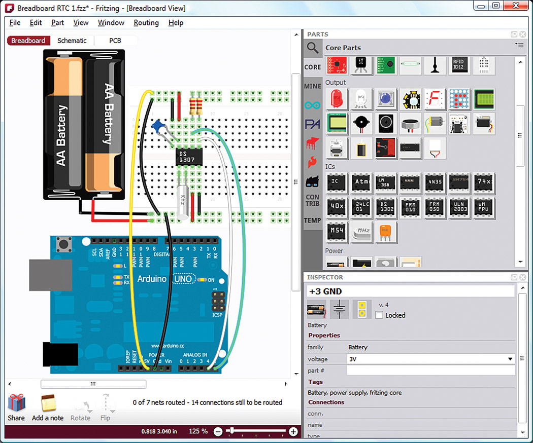
FIGURE 1. A real time clock on a breadboard.

FIGURE 2. The schematic.
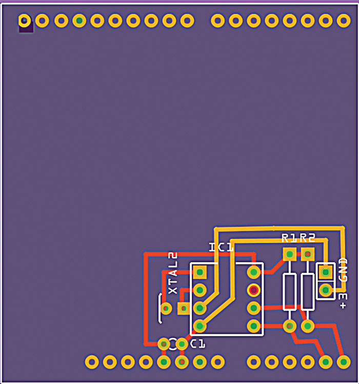
FIGURE 3. The PCB.
The PCB is shown front and back in Figures 4 and 5.
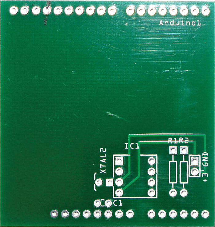
FIGURE 4. Fritzing RTC PCB, top side.
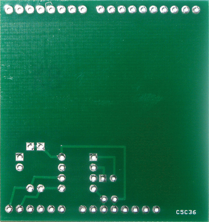
FIGURE 5. Fritzing RTC PCB, bottom side.
The RTC part of the design is fairly small and tucked away in the bottom left corner to be near the Arduino pins needed to provide power and the I2C connections required by the DS1307 chip. That seems to leave a lot of wasted board space, and indeed when I designed (not using Fritzing) a nearly identical circuit, I made the board much smaller. Remember, though, that the purpose of all this is to introduce Fritzing and how to use it to design an Arduino shield. To be a compliant shield, you need the PCB to fit on an Arduino — thus, the rows of holes on the top and bottom to fit over the Arduino connectors.
GETTING BETTER ACQUAINTED WITH FRITZING
Fritzing is a too-cool tool. We’ve had a decent introductory ‘quick start.’ Let’s drill deeper and see what else we can do. Please note that Fritzing is evolving and works on several platforms, so your version may not be exactly what is shown here, but it should be close enough that you can figure out the (hopefully) slight differences.
Figure 6 shows the necessary parts, which are listed in Table 1.
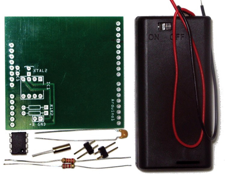
FIGURE 6. RTC PCB and parts.
| Qty |
Name |
Distributor Part # |
| 1 |
DS1307 |
Mouser 700-DS1307 |
| 1 |
32.768 watch crystal |
Mouser 815-AB38T-32.768KHZ |
| 1 |
Cap 0.1 µF |
Mouser 21RZ310-RC |
| 2 |
Resistor 2.2K ohm |
Mouser 660-MF1/4DCT52R2201F |
| 1 |
Battery box - 2 AA |
Jameco 216120 |
| 2 |
Two-pin male header |
Jameco 108338 |
TABLE 1. RTC bill of materials.
Figure 7 shows the board with the parts soldered on and plugged into an Arduino for testing. Plug it into the Arduino as shown in Figure 8. Yup, it worked using the DS1307 RTC software discussed in Workshop #48.
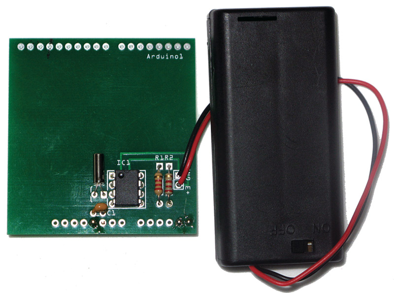
FIGURE 7. The built RTC PCB.
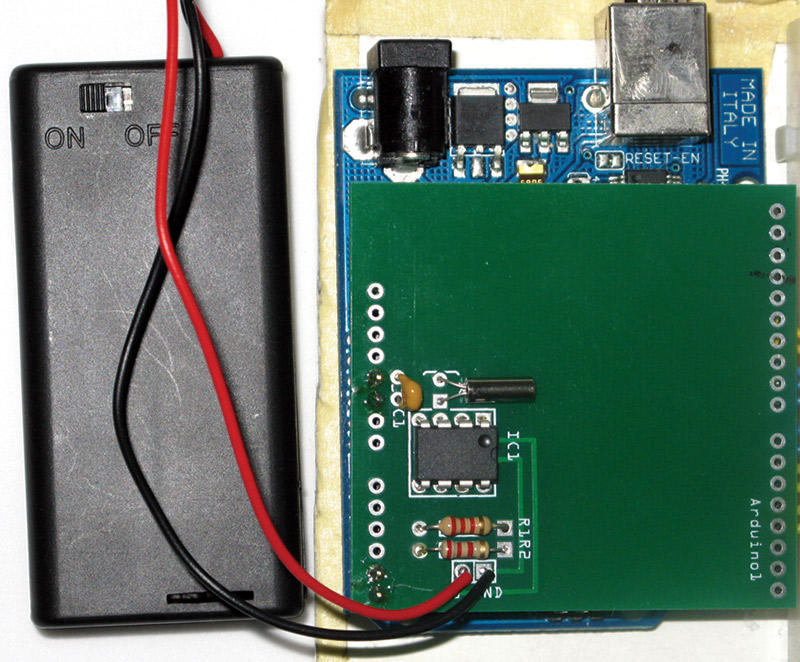
FIGURE 8. RTC PCB tested on an Arduino.
So, you noticed all that empty space. And we mentioned why we can’t make it smaller. We would have to design another part that would represent only those pins on the lower part of an Arduino shield, and then actually only four of those pins. To do that, we would need to design our own part. We’ll get to that momentarily.
Window Views
Open the Core parts bin, and drag and drop the generic IC onto the breadboard as shown in Figure 9.
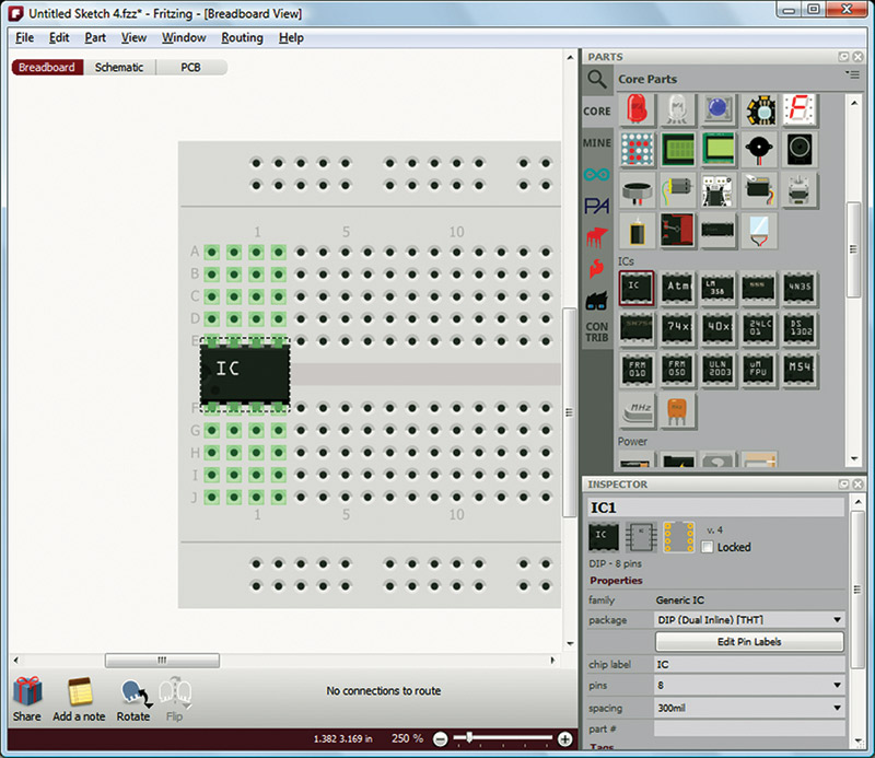
FIGURE 9. Select a generic IC.
In this view, we see the Parts and Inspector views on the right of the Fritzing window. These items are docked to the right, but can be dragged out and undocked as shown in Figure 10.
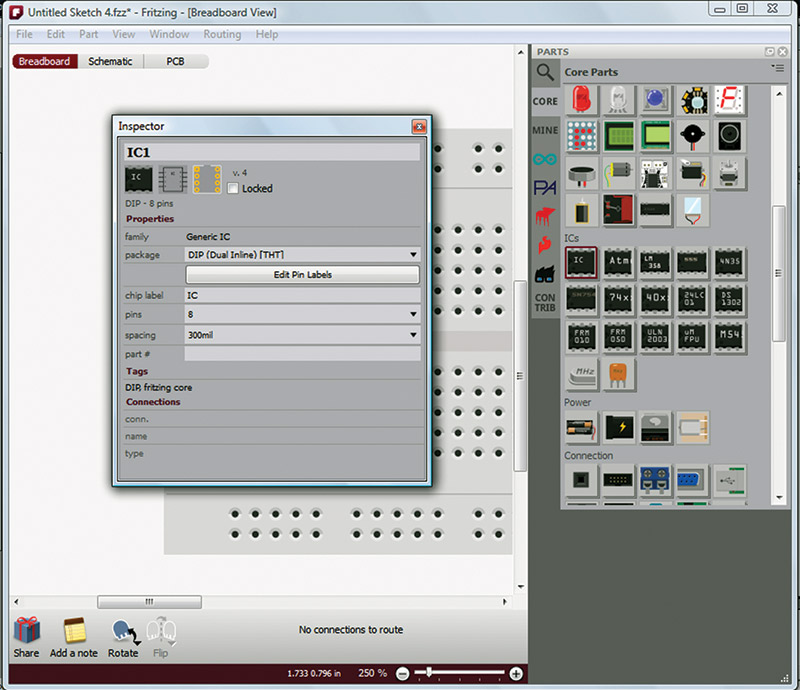
FIGURE 10. Inspector undocked.
There are other windows that we can view by opening the Windows menu item as shown in Figure 11.
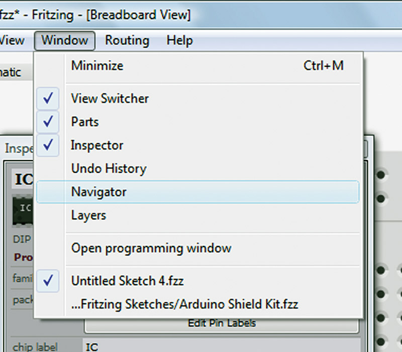
FIGURE 11. Other windows.
Having all the windows open and docked on the right makes things a bit crowded, so undocking them while using them makes most sense as shown in Figure 12.
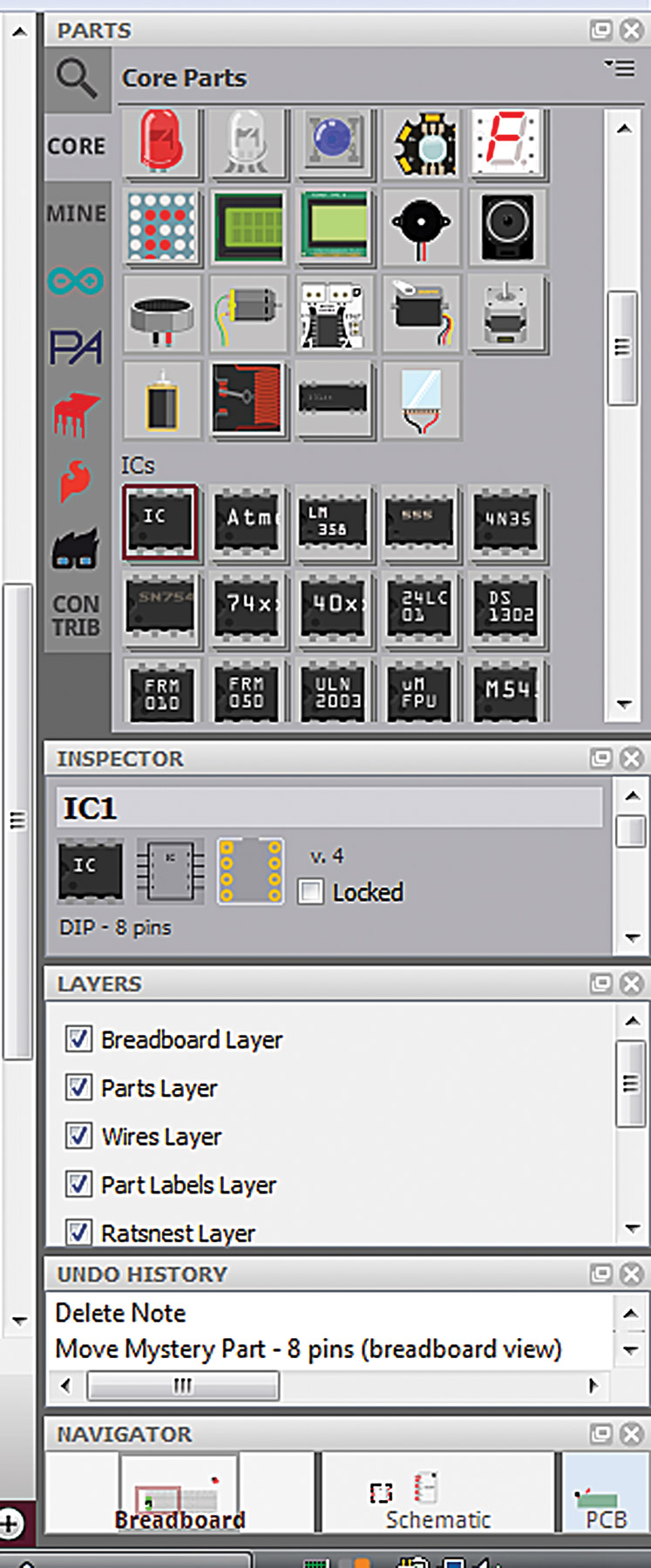
FIGURE 12. All windows open.
Setting Preferences
The Preferences dialog (Figures 13 and 14) has four tabs for setting preferences for Fritzing: General, Breadboard View, Schematic View, and PCB View.
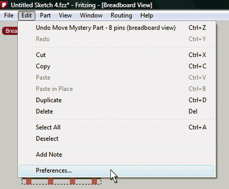
FIGURE 13. Select Preferences.
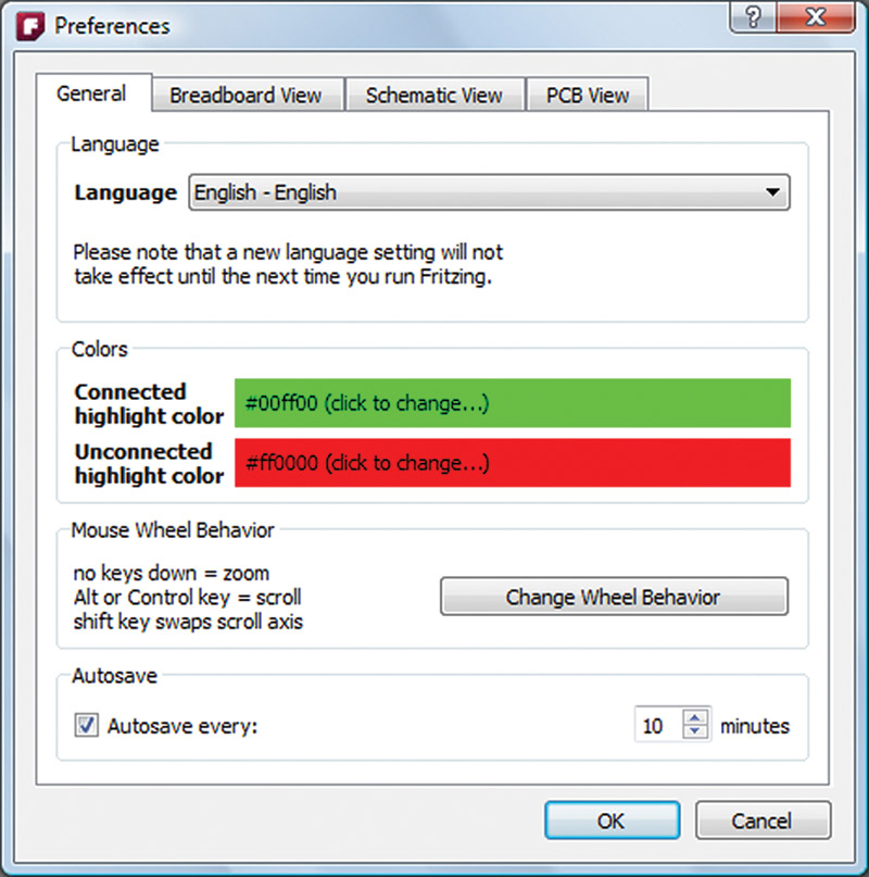
FIGURE 14. Preferences dialog box.
In the General tab, we see that we can select from a bunch of languages, but we’ll leave it on English. Also, we can change Colors for highlighting, plus we can change the mouse wheel behavior and whether we autosave or not, and if so, how often. Let’s leave these at their default values.
In the Breadboard View tab shown in Figure 15, we see that we can set the background color.
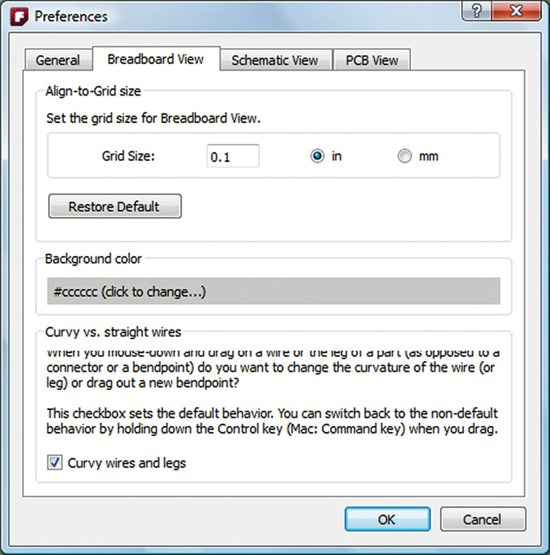
FIGURE 15. Preferences Breadboard View.
Clicking on that gives us Figure 16, where we click on Custom Color that gives us the dialog box shown in Figure 17.
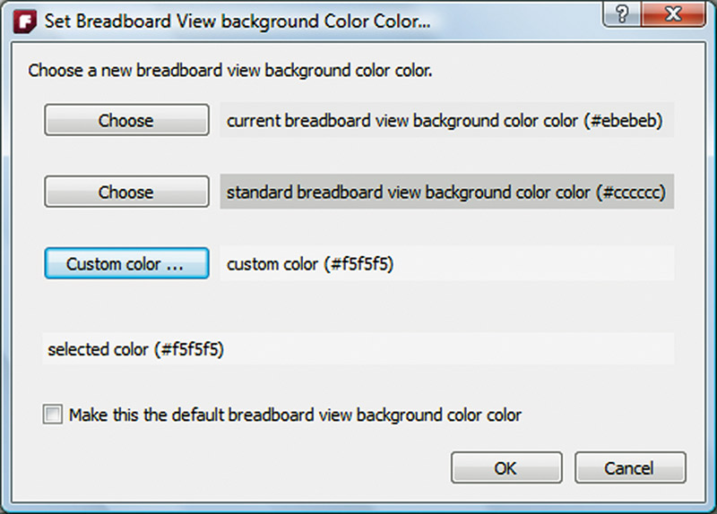
FIGURE 16. Set the Breadboard View background color.
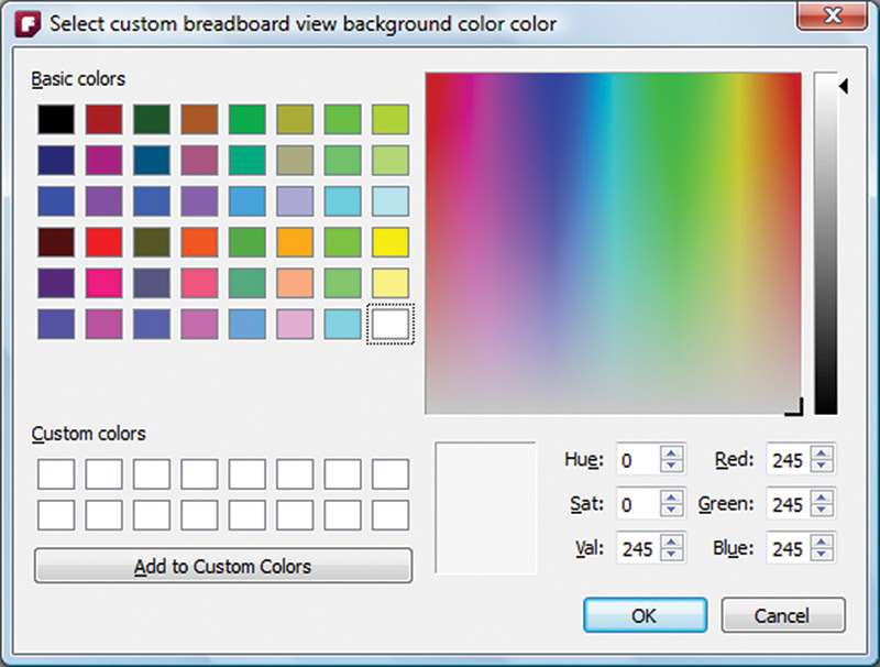
FIGURE 17. Set the Breadboard View background custom color.
We then select the Val for 245 which gives us a much lighter gray background that provides better contrast with the breadboard parts (in my opinion).
You can open the other tabs and change the colors for the Schematic or PCB View as you prefer. I lightened up the PCB background — again for better contrast — but you might like it the way it is.
Add a Note
You can add a note to your project by clicking the icon shown in Figure 18.
FIGURE 18. Add a note.
You can resize the note, move it around, and input multiple lines as shown in Figure 19.
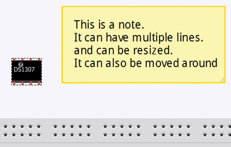
FIGURE 19. An actual note.
Part Floating Menu
Move your cursor over a part and click the right button to open a floating menu of options for things you can do with that part. Figure 20 shows the example of ‘Rotate 45º Clockwise.’ Play with these features for a while to get familiar with them.
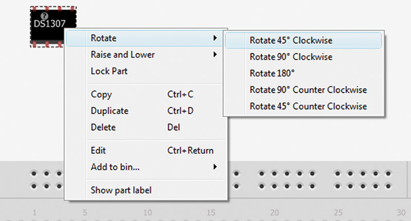
FIGURE 20. Part Floating menu.
CREATING PARTS IN FRITZING
Using the Generic IC to Create a 74HC595 Shift Register
Many of the core parts in Fritzing are generic and are quite easy to modify or create new parts with. We'll look at how to turn the generic IC into a 74HC595 serial-to-parallel shift register. This part is available in the Fritzing core, but we'll build this part as an exercise to get better acquainted with Fritzing's features. Drag and drop a generic IC from the Core bin of the Parts dialog box onto the Breadboard View, then undock the Inspector dialog and set it next to the part as shown in Figure 21.
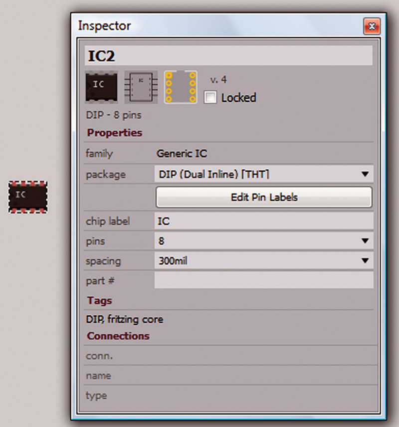
FIGURE 21. Generic IC.
In the Part Inspector, we change the top input box from IC2 to 595, and the chip label to ‘595. Take a moment to open the package drop-down menu and you’ll see a long list of possible packages — mostly SMD that we won’t be using. Change the pins from eight to 16, giving us the new Breadboard View part shown in Figure 22.
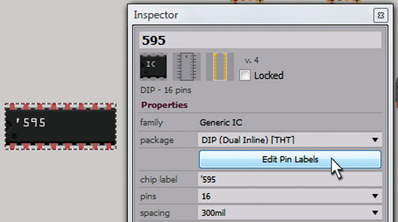
FIGURE 22. The 595 Edit Pin Labels.
Click the ‘Edit Pin Labels’ button to open the dialog shown in Figure 23.
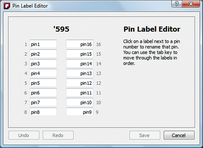
FIGURE 23. Pin Label Editor.
Now, open a datasheet for the 74HC595 (actually any 74xx595 part will do) as shown in Figure 24 and then change the pin labels to match Figure 25.
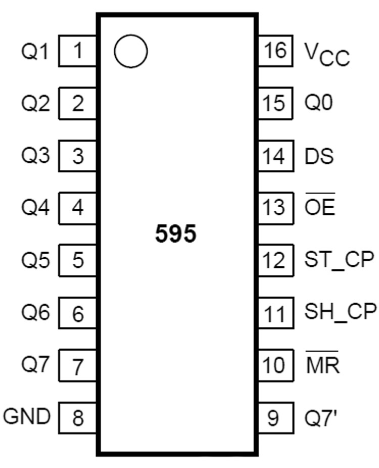
FIGURE 24. The ‘595 pins.
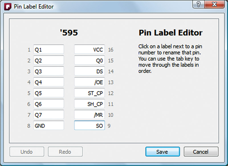
FIGURE 25. Pin labels for the ‘595.
Now, we have a new part for the ’595 serial-to-parallel converter. Figure 26 shows the new ’595 part in the three views (Breadboard, Schematic, and PCB). (By the way, if you’re wondering why I selected the ‘595, you might want to take a look at Workshops 27 & 28.)
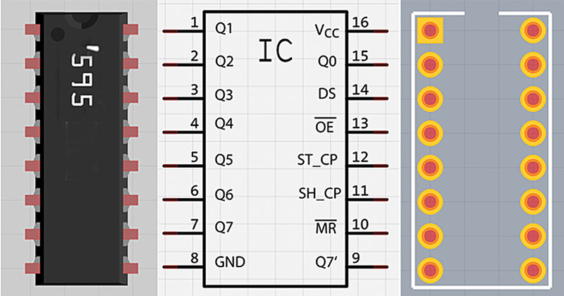
FIGURE 26. The ‘595 part for the breadboard schematic and PCB.
Using the Mystery Part to Create a Partial Arduino Shield
Fritzing has a mystery part that is somewhat similar to the generic IC. We will use it to create a new part that represents the bottom row of an Arduino shield so that we can repeat the RTC circuit design, but for a much smaller PCB (the RTC doesn’t need the top row of the Arduino, so why include it?). So, let’s use these parts to redo the RTC PCB from our last episode. Open that file and save a copy — just in case.
Select the mystery part from the Core Parts bin and you’ll see the part as shown in Figure 27.
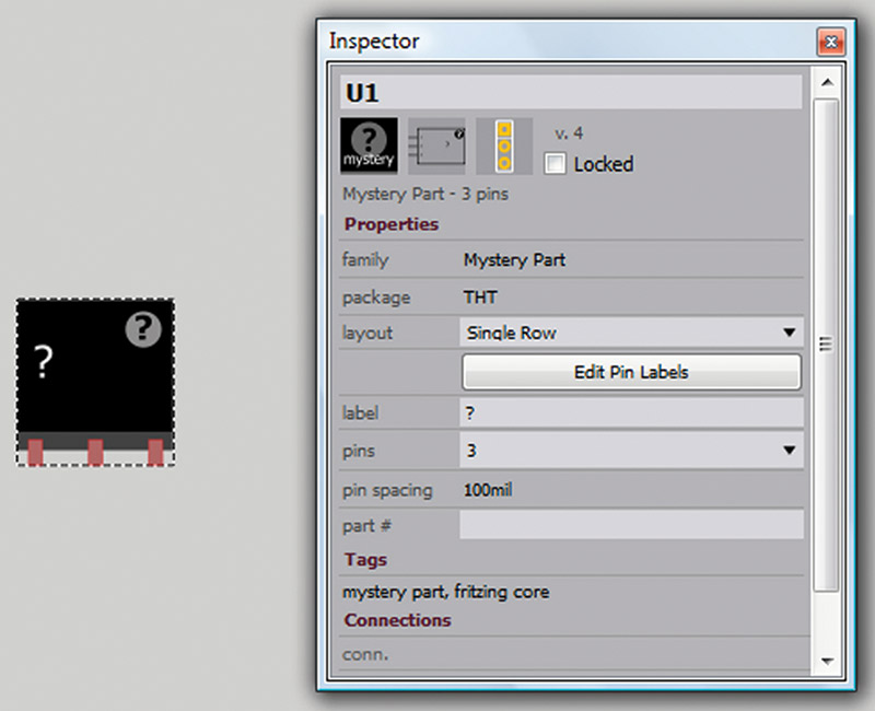
FIGURE 27. The mystery part Inspector.
We will use this to create a part for the Arduino analog pins. Set the ‘pins’ to six, change the name from U1 to Arduino Analog, and then use the ‘Edit Pin Labels’ to change the pin names to A0 to A7. Double-check that you’ve labeled them correctly as shown in Figure 28.
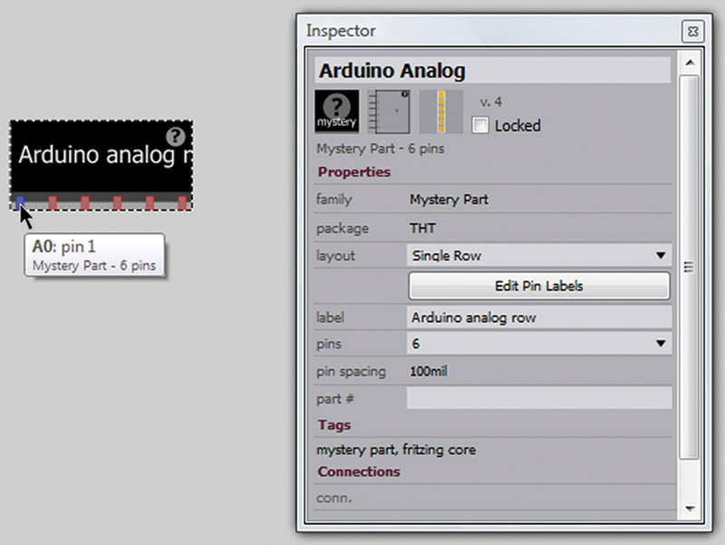
FIGURE 28. The Arduino analog row.
That was easy, so let’s follow the same procedure and create an Arduino Power Row part that we will use to make a new PCB with only the Arduino bottom row.
Figures 29, 30, and 31 show how we used these two parts to replace the Arduino in our design (you might want to refer to our last Workshop for the original process).
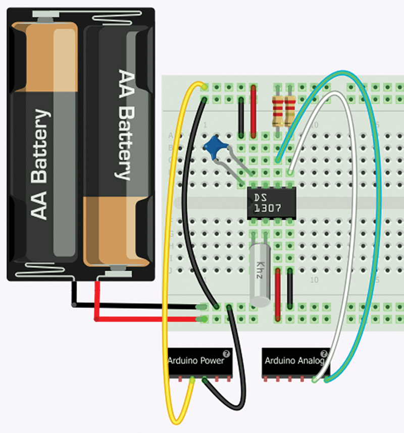
FIGURE 29. New RTC breadboard.
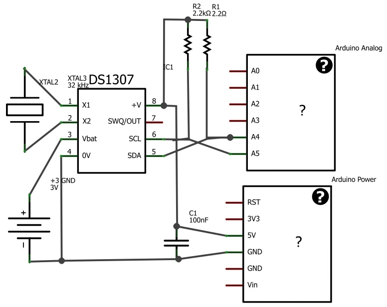
FIGURE 30. New RTC schematic.
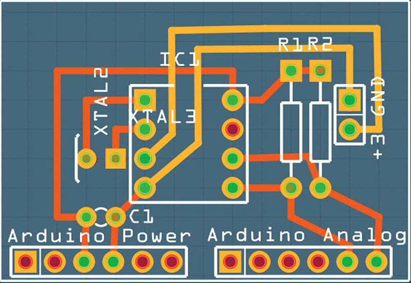
FIGURE 31. Smaller RTC PCB.
One thing to notice is that the breadboard image doesn’t relate to the real world since we don’t actually have physical parts that are the Arduino Power and Analog Row — we are still using the Arduino in our real world breadboard, but we are substituting these ‘virtual’ parts so we can get our smaller PCB.
So there you have it. Our PCB is less than half the original size and will be proportionally cheaper to fabricate.
Using the Design Rule Check
In the PCB View, open the Routing menu and select (DRC). Uh oh! Figure 32 shows that we’ve broken some rules.
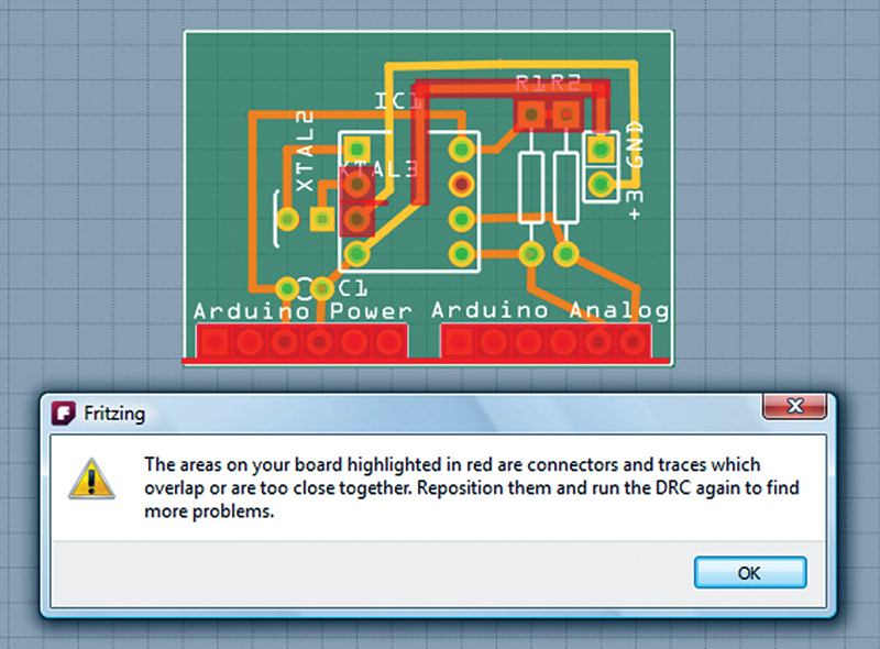
FIGURE 32. Design Rule Check Bad window.
So, we move things around a little and repeat the DRC; we get Figure 33. It is now ready to go.
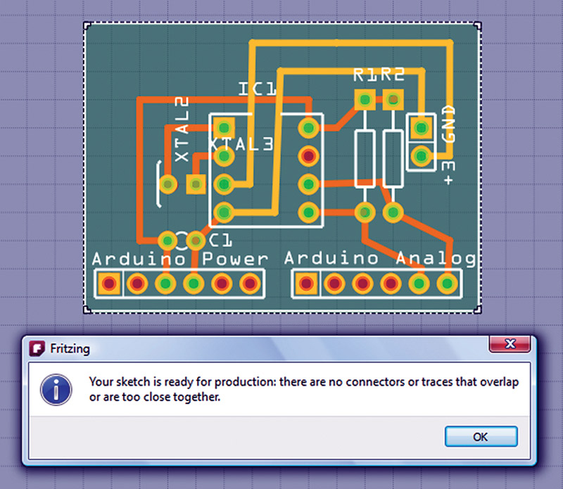
FIGURE 33. Design Rule Check Good window.
MODIFYING AN EXISTING PART
Using Inkscape to Modify the Part
I chose Inkscape — an open source SVG graphics editor — to modify this part in the .svg format used by Fritzing because it is not just free, but a darn good program. I also have the expensive Adobe Illustrator program that draws .svg parts, but I find it less easy to use than Inkscape, so why bother?
I am going to have to assume that you either know how to use vector graphics drawing programs or are willing to learn since it would take many Workshops to explain how to do this.
Let me just say that I keep a browser open and Google almost every action I take when drawing because the procedures are arcane (in both Inkscape and Illustrator) and far from intuitive. I will give a few hints along the way, though, for issues that might take you too long to figure out on your own.
We will only use Inkscape superficially to modify a part, but next time we will use it to create a part from scratch. So, if you think you’re going to really get into making parts with Fritzing, I suggest you take some time to learn Inkscape. The effort will come in really handy in the next Workshop.
Another way to create a part is to modify an existing part. This is a lot harder though, and requires messing with the .svg file, so be forewarned. Let’s fix that seven-segment LED part, which just annoyed me from the get-go. I wondered why, and then I realized that it was displaying the letter F (Figure 34). Being grade conscious, I wanted an A.
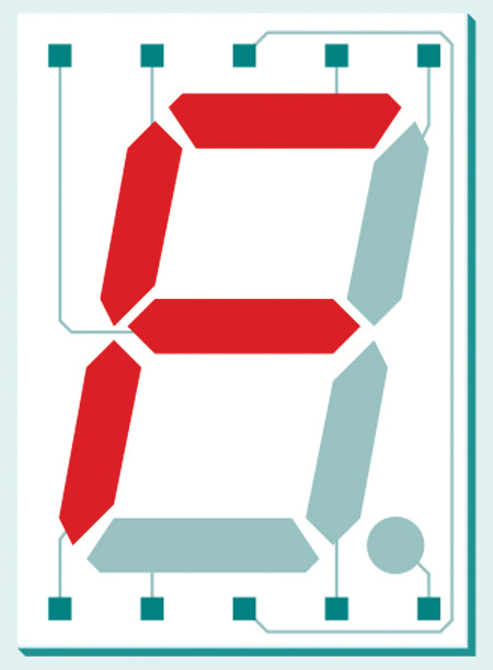
FIGURE 34. Seven-segment F.
You can find this part’s drawing in the Fritzing directory under \parts\svg\core\breadboard\7-segment_13.svg. Before messing with it, make a copy and paste it in the directory so you can restore it if you flub something up. Drag the part into Inkscape. Make sure you set Inkscape up as before with the 0.1” spacing and the page resized to fit the part.
Select the object and ungroup it. I do this by selecting the part and then holding down the shift and ctrl key, then pounding on the ‘g’ key until all the sub-object borders appear as shown in Figure 35.
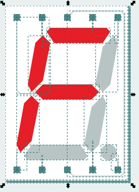
FIGURE 35. Seven-segment object borders.
Next, use the arrow key to highlight each of the gray segments on the left and then select the ‘Pick Colors from Image’ tool on the left. Click a red segment which changes the color of the selected segment to that same shade of red as shown in Figure 36.
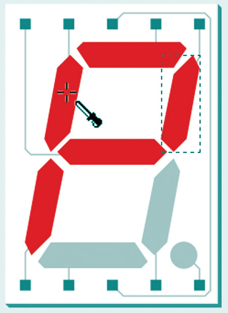
FIGURE 36. Pick colors from image.
Repeat for the lower right segment and you’ve turned the F into an A. Another problem for me was that my particular real world seven-segment LED isn’t white, but a light gray.
So, I selected the white background box and clicked a light gray color. I then clicked the Object menu group item which gives me the image shown in Figure 37.
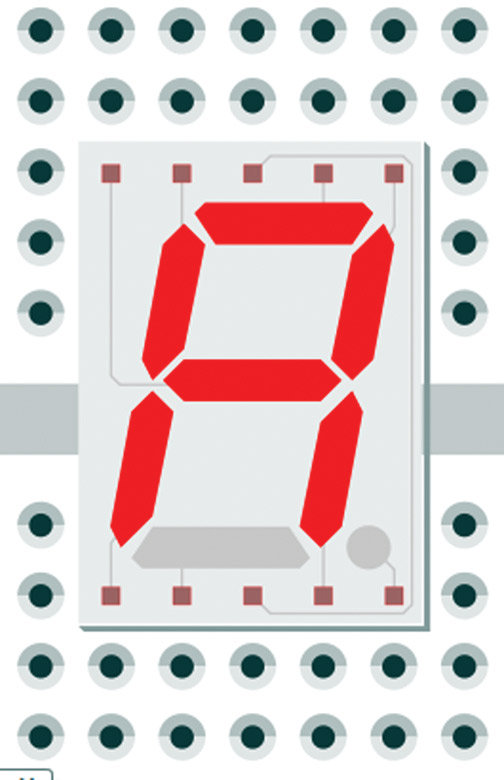
FIGURE 37. Seven-segment A.
Now, open the grid, set it to 0.1”, and disable the snap. You’ll notice that the pins are not on 0.1” centers. Change the size of the part so that the pins fit 0.1” centers, and the upper and lower pins are 0.6” apart.
Finally — and this is critical — before saving this part, resize the page to fit the part and then — even more critical — save the part as a plain .svg, not an Inkscape .svg (I forget this nearly every time). When you open the 13 mm seven-segment LED in Fritzing, you will see (as shown in Figure 37) that you are now getting an A. Good for you!
Our next Workshop will go a bit deeper into making parts with Fritzing. Some of this will be easy, some hard, and some darn near impossible — but hopefully my hints will help keep you from bloodying yourself on some of the same walls I smacked into. NV