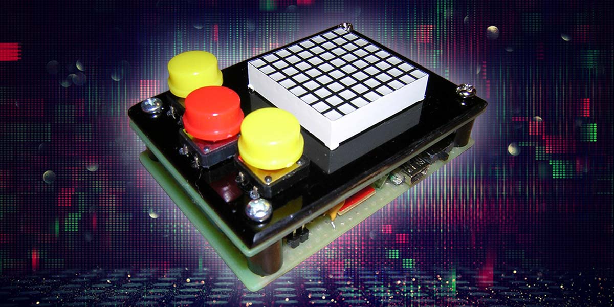
Those 8 x 8 matrix displays are good for more than just making scrolling signs. With a little imagination and a whole lot of extra time on your hands, you can actually use them to create simple yet amazing little action games. No matter how many or how few pixels you have at your disposal, the theme remains the same. It is always a matter of destroy or be destroyed, chase or be chased, or something along these lines. If the game is interesting enough, at some point you stop noticing that it is taking place on a field of only 64 LEDS. The only thing that matters is victory.
Matrix Displays
The most common, simple, and least expensive matrix display is an organization of 64 single or dual color LEDS arranged as eight rows by eight columns. The footprint standards for these displays are typically referred to as small, medium, and large, ranging in size from 3/4 to 1.5 inches square. These LED displays come in two distinct polarity types defined as Anode in Row or Cathode in Row, which denotes how the rows are connected to the diodes.
This polarity definition is important at a programming level, by defining whether a low or high command is issued to light the individual LEDs. The illustration in Figure 1 shows a common organization in which the rows are all connected to the common cathode side of the diodes.
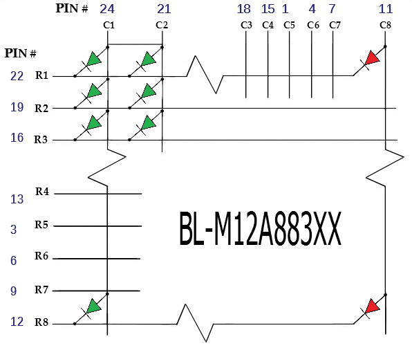
FIGURE 1. Diode connections for a dual color matrix.
The 24-pin dual color displays are all pretty standard as far as pin numbering. I find that the square pattern LED is a better choice for most game play. The square pattern display seems to be less common than the traditional round pattern. Adafruit is a good source for high quality dual display units but they can be had from various places. Futurlec sells a less expensive 16-pin single color display.
All that is needed to illuminate any individual (or combination of) LED is to bring a single or multiple set of rows high, and to strobe the associated column connection to turn the diode(s) on or off. Each LED will illuminate brightly at 3 mA when pulsed at around 50 msec. To discretely turn all of the 64 LEDs on or off will require at least 16 I/O lines from any common microcontroller, or eight port control for the rows and a shift register to control the columns.
In the event that all the LEDs must be turned on or appear on, the device driving the LEDs must be able to source 3 mA x 64 without using a buffering scheme such as discrete transistors or a transistor array package. The PICAXE 28x2 has a total of 20 bidirectional ports and has a maximum current rating of 200 mA. By designing a display driver using only a low voltage microcontroller, we can build a game that can run at least eight hours between charges with a single lithium battery rated at less than 200 milliamp hours.
How the Design Works
Any game worth playing will require at least three buttons for control. Two of the three buttons should be dedicated for directional maneuvering. A third button is essential for actions such as firing control, and can be used for starting the game. The addition of sound capability is also a must for any game design.
Without using a shift register for row control, 16 I/O ports are used for the display. Three ports are used for pushbutton switch input and the remaining single port is used for audio, for a total of 20 I/O ports. Only the display and pushbuttons are located on one side of the board as illustrated by the schematic shown in Figure 2.

FIGURE 2. Circuit schematic for the project.
The three pushbutton switches connect to the upper side of the board. I purposely located the center pushbutton switch offset lower to the other two directional buttons. This is a subtle change that makes a difference given the function of the switch.
You may notice that the eighth column for the display is connected to the red columns of LEDs. This was done specifically for the game that is included with this article. Row 8 is the lower horizontal array and is used for the player paddle construct. You may want to include a jumper to select the green or red color for this column in future games, as shown in the connection to port C.0.
The bottom side of the board holds the lithium battery, a lithium cell charging circuit, the USB-A female socket, and the PICAXE programming port. The lithium battery used is a 3.7V, 140 mAh lithium polymer type which will survive at least eight hours of constant use. This battery is really small with a footprint of only 34 mm x 20 mm x 4 mm.
The schematic shows how the PICAXE connects to the other components of the system. As you can see, the display is connected to 16 bi-directional ports on the PICAXE. The three SPST tactile switches connect to three of the PICAXE ports, and are all configured with 10K pull-down resistors with the button tied to the supply voltage. Connecting the buttons in this fashion will present a logic high to the associated pins when they are depressed.
The piezo element speaker is connected to port B.7 and is interfaced using a 10 µF electrolytic to increase the sound volume. The two programming pins — serial IN and serial OUT — are connected to a stereo jack. This is the typical connection method for programming the PICAXE, converting USB to serial. The 28X2 PICAXE only requires an external crystal to run at frequencies higher than 16 MHz.
The board has been designed to add a resonator later if needed. A miniature right angle slide switch is used for on/off control by breaking the connection to the 3.7V battery supply for the circuit. The circuit is configured to begin charging the 3.7V lithium battery once power is supplied to the USB connector. Charging is accomplished by way of the MAX1811 single cell lithium battery charging manager. The MAX1811 can be configured to charge either 4.1V or 4.2V standards, and at selectable current settings.
The schematic connects the MAX1811 to deliver 500 mA for charging. The MAX1811 displays charge status by lighting an LED at the 2.4V mark and extinguishes once the battery is charged. Unfortunately, the MAX1811 is only manufactured as a surface-mount part and has to be soldered onto an SOIC to DIP adapter board. The illustration in Figure 3 shows how this is accomplished.
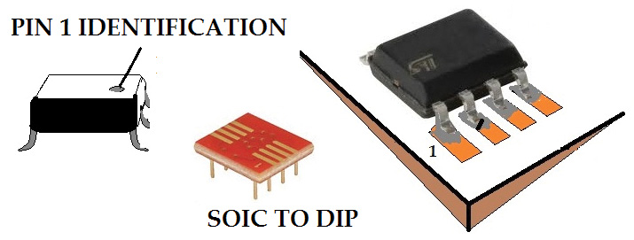
FIGURE 3. Mounting the MAX1811 to the SOIC to DIP adapter board.
I find that it helps to hold the chip in place with an alligator clip or by using double-sided tape before you begin soldering the part to the board. Just be sure to use an adequately heated soldering iron (375 deg) with a proper tip for the task.
Once adapted to DIP, the board can be soldered to the circuit board or in an eight-pin socket.
Designing the Circuit Board
To construct the circuit board for this project, I used a double-sided plated through hole board I purchased from Jameco. I modified the board slightly with a Dremel tool by reducing the space to the sides for mounting the programming socket and miniature right angle slide switch.
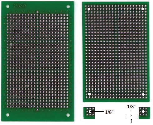
FIGURE 4. Modification of the plated through hole board.
Without trimming the sides, the audio socket and slide switch are too far from the edges. It is a good idea when designing a circuit like this to actually assemble the pieces first before soldering the parts. The illustration of Figure 5 is an example of an assembly using the standoffs to make sure that all of the holes line up and that all the parts have proper clearance.
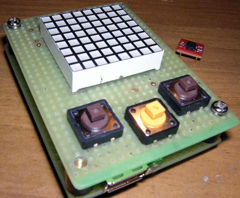
FIGURE 5. Trial assembly of the board using standoffs.
I captured the 29 x 32 pattern of the board using a vector graphics editor. I keep a small library of the images for the parts used in the circuit and replicated the placement using the editor. I use this graphic to plan the interconnections between parts to reduce possible errors. The placement of the components for the top and bottom side of the board along with all the connections is shown in Figure 6. These views can be really helpful when it comes time to solder connections to the board.
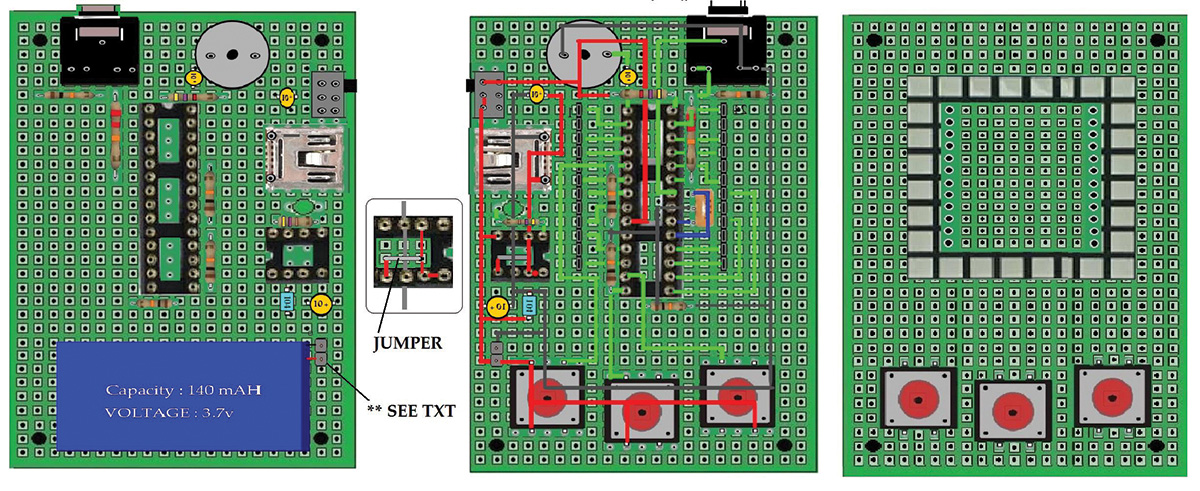
FIGURE 6. Parts placement and interconnect scheme for the circuit board.
I reflected the placement of the parts to help prevent the typical PIN1 orientation error for the two chips used in the circuit. The post shown connected to the battery in the bottom side component view is a two-pin male header. This is something I used as an easy test point and is not required for the circuit to operate. When there are many closely spaced routes on the board, sometimes I find it easier to trace an outline of the route using an ultra fine felt tip pen as a guide. It then just becomes a matter of point-to-point wiring.
There is only one jumper used on the board. It fits neatly under the eight-pin socket for the MAX1811 and it is shown as a close-up in Figure 6. Any interconnect technique should work fine using this plated through hole board. My favorite two methods are shown in Figure 7, but use any connection technique you prefer.
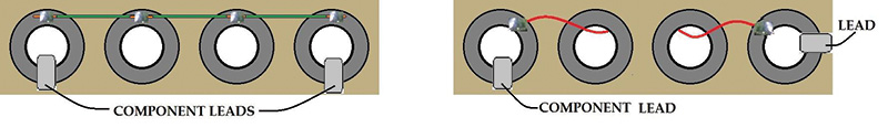
FIGURE 7. Interconnect techniques with plated through holes.
The current flowing through the connections is very low so you can use a thin gauge wire that will make it easier to cover up with the faceplate. Keep in mind that with a plated through hole board, the interconnect can happen on either side. I used whichever side was easier to solder and kept most of the connections on the side that had the most components. By using 30 AWG magnet wire, the component leads and wire can fit in the same hole before and after soldering.
To build this circuit, the prototyping board must have plated through holes. The reason for this is because components need to mount on both sides of the board, so a single-side plated board will not work. To cover up the solder points on the top side of the board where the pushbuttons and display are mounted, I used a piece of high gloss black plastic I bought at a hobby store. The problem with this is that you have to drill holes in the plastic to allow the pins from the display and leads from the buttons to feed through.
I used a fine-tip pen to mark the locations on the plastic and used a 1/16” inch drill bit to make the holes. The matrix leads just make it through to the backside of the circuit board for soldering, but the leads on the buttons are too short. This problem can be easily fixed by soldering extensions onto the leads as shown in Figure 8. The screws included with the standoffs have built-in lock washers that need to be removed to allow the threads to reach through the faceplate. The design needs to have a bottom board; this can be anything you like. I used the same black plastic that was used as a cover plate.
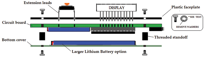
FIGURE 8. Parts placement for the top and bottom side of the board.
This board performs two tasks. It covers the mounted components and provides a back plate to hold on to when playing the game. Another possible benefit is that it can be used to mount a larger lithium battery if you want a longer period between charges. You can easily fit a 1,000 mA battery in the space between the threaded standoffs. I listed the catalog number for this as optional in the Parts List. SparkFun sells a pack of 12 key caps specifically for the tactile switches used for the circuit; they help add a real professional look to the game.
Parts List
| ITEM |
QTY |
DESCRIPTION |
|
| IC1 |
1 |
PICAXE 28X2 controller |
|
| PZ1 |
1 |
Piezo transducer |
|
| SW4 |
1 |
Slide switch |
|
| IC2 |
1 |
Battery manager |
|
| USB |
1 |
USB-A jack |
|
| SW1-3 |
3 |
Tactile switches |
|
| C1, C3, C4 |
3 |
10 µF tantalum |
|
| J1 |
1 |
3 mm audio jack |
|
| D88 |
1 |
(8x8) dual color matrix |
|
| B1 |
1 |
260 mAH LiPo battery |
|
| Standoffs |
1 |
Package of four |
|
| R2-R5 |
4 |
10K 1/4 W resistors |
|
| R6 |
1 |
470 1/4 W resistor |
|
| R1 |
1 |
4K7 1/4W resistor |
|
| R7 |
1 |
22K 1/4W resistor |
|
| SOIC to DIP |
1 |
Breakout board |
|
| D1 |
1 |
3 mm green LED |
|
| Circuit Board |
1 |
Prototyping board |
|
| Optional Parts |
| Asst key caps |
1 |
Pkg of 12 asst key caps |
|
| 1,000 mA battery |
1 |
Larger lithium battery |
|
| 16 MHz XTL |
1 |
External oscillator |
|
| 28-pin socket |
1 |
28-pin socket for PICAXE |
|
| Eight-pin socket |
1 |
Eight-pin socket for MAX1811 |
|
| Miscellaneous hardware/tools |
| Plastic for faceplate/backplate |
| Dremel tool |
| Drill with 1/8 and 1/16” bits |
| Soldering iron |
Checking Your Work
Once you have mounted all of the components, it is time to test the circuit. Before you insert the 28x2, turn the slide switch to the on position and test the supply voltage from either ground pin to the +V on pin 20 of the PICAXE. If the supply voltage is fine, insert the processor and connect the programmer to the audio jack. Load the test routine to exercise the buttons, sound, and matrix display.
Once loaded, there should be a blinking square in the center of the display. Depress the left and right buttons, and the square should move from left to right. Press the center button, and the box will extend outward with a changing tone as it expands. This test guarantees a working display, button control, and sound. The code for this test can be downloaded from the article link, along with the example game; file name is GAME_DIAG.BAS.
How the Game Works
Once you have tested the components of the circuit, you will want to load the example game for the project. The game is entitled DEFLECTO. This BASIC program serves as an example as to how easy it is to program this circuit.
The game begins in the ready to start mode with a red game paddle moving back and forth until you press the center button. After pressing the center button, a ball descends at some random angle toward the bottom of the display as shown in Figure 9.
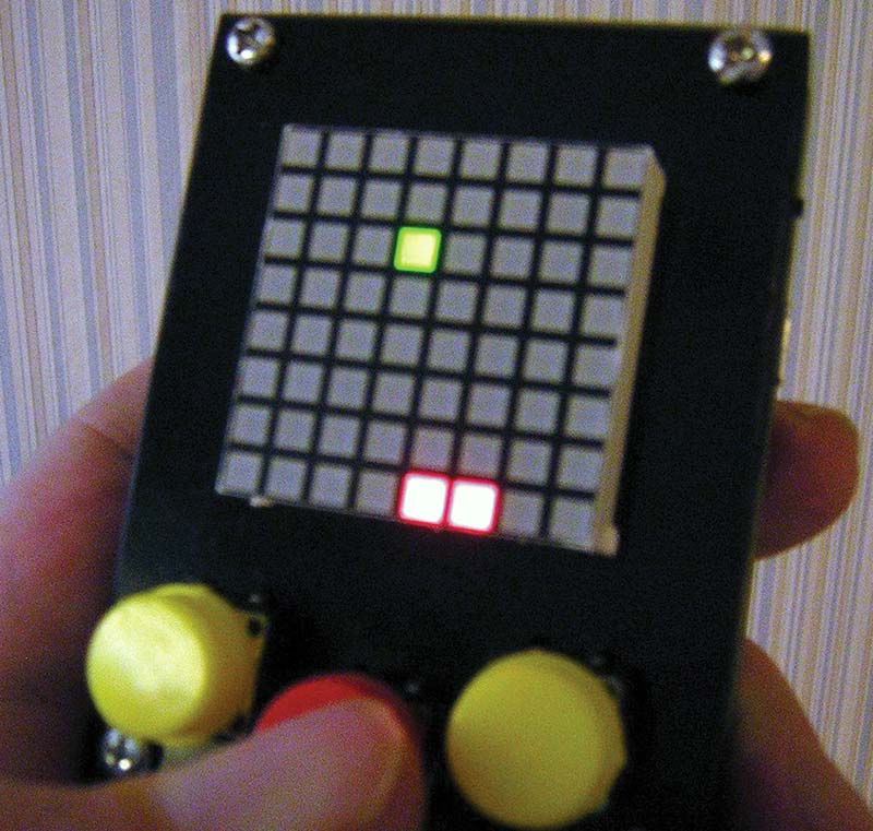
FIGURE 9. Shot of a typical game starting.
The incoming ball can be deflected by positioning your paddle using the left and right buttons. If you miss the incoming ball, a MISS sound occurs and you must press the center button again to initiate the next ball. If you deflect the ball, it returns upward at an appropriate angle back toward the top of the display.
As the balls get deflected, it turns on the pixel that gets struck as it hits the boundary. If the ball strikes a tile that has already been lit, the ball gets deflected and returns as the ball in play. The game is won after lighting all the tiles across the top.
You may want to rewrite the program so that you must keep the last ball in play until you strike the last tile or you lose all of the seven previously turned on tiles.
I have broken down some of the key elements of the game design in hopes that it may help you to understand the program better. The specific named ports that tie to the rows and columns of the display have been symbolized to make programming easier. The primary routine in the game is the player paddle position. Figure 10 illustrates the seven positions the paddle can be in during game play.
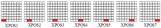
FIGURE 10. Example paddle positions.
The program sets paddle positioning as the primary event, and polls the left and right direction buttons between the start of all other events. A variable used to represent the symbol XPOS is incremented or decremented with each push of the buttons tied to ports C.2 and C.3. If XPOS = 1, row R7 and R8 are held low and column C1 is toggled to light the leftmost paddle position. For the incoming balls, fixed diagonal or vertical lighting subroutines are jumped to randomly whenever the center button connected to the port C.3 is pressed.
There are eight angled inbound ball routines along with six angled and two vertical outbound returns as shown in Figure 11. The game seems very intelligent and complicated when playing, but literally only took about an hour to write.
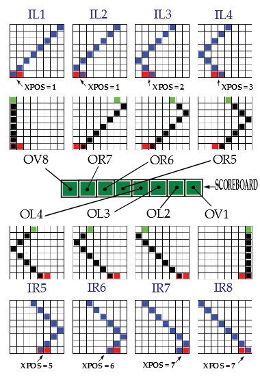
FIGURE 11. Lighting the top eight LEDs with the eight outbound balls.
Deflecting the inbound balls by moving your paddle position to intersect the incoming ball, the rebounded balls should strike all eight upper tiles eventually after successfully returning all eight volleys. Depending on the exact paddle location, the ball returns in a corresponding manner. For example, if the inbound ball IR5 meets a paddle in XPOS = 4, the ball returns vertically.
If the paddle is at XPOS = 5, the ball is returned at an angle. Whenever a deflected ball strikes the top boundary, the individual top LED becomes lit. The game is won after all eight positions have been hit.
The program contains all of the elements you will need to write your own games, including sound routines, button action routines, position tracking, and more.
Game Over ...
Substitutions can be made for most all of the parts in this project. You may have to abandon the exact design if there are great enough differences in size, shape, and lead spacing of the substituted components.
Also, any 24-pin display will work along with any 16-pin models with the appropriate modifications.
I hope that any readers that build this project share their programming efforts in the comments below. NV