Over the past several Workshops, we have been learning to use the Arduino handheld prototyper — a device that lets us design our prototypes on a breadboard with the Arduino proto shield and communicate with the I2C mini terminal — both of which are tied together with a plastic base so that you can carry the entire development system around in your hand (or hang it on a wall as shown in Figure 1).
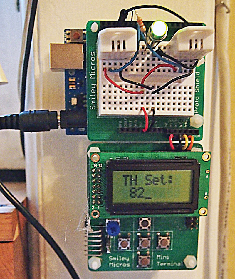
FIGURE 1. Fresh air controller prototype.
Last episode, we began looking at a design using this system for a fresh air controller. This time, we will finish that design — mainly seeing how to communicate with the user via the I2C mini terminal LCD and pushbutton keys. Since we pretty much stopped in mid-sentence talking about the software, I recommend you reread te previoust article. (It's Workshop #62 in the sidebar)
Previously, when we discussed the fresh air algorithm, we specified that the user should set the variables for the high and low temperatures and the humidity. We could do this via the Arduino USB over the serial port of a PC but then it wouldn’t really be ‘handheld,’ would it? For the system to be portable, we have to cut the apron strings from mommy PC and go it alone. To do this, we will use the I2C mini terminal part of the Arduino handheld prototyper.
We introduced how to use the I2C mini terminal over the past two articles; now we will see how to apply it to a real world application: Getting user feedback from the keys and displaying useful information on the LCD for the fresh air controller. We will write a program that has two basic modes: an idle mode for when the user is not accessing the system; and a menu mode for when the user wants to access the system by pressing a key.
The decision for which mode to run is made in the Arduino loop() function where we run the idle() routine until we receive a center (CTR) key press (Figure 2).
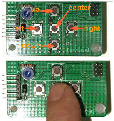
FIGURE 2. Press the center key.
Then, we run the menu() routine to get the user input. When the user is finished, we return to the idle mode. The loop() function is written as follows:
void loop()<br />
{<br />
 if(idle()) // returns 1 if any new key is<br />
           // available<br />
 {<br />
   if(newKey)<br />
   {<br />
     if(newKey == CTR)<br />
     {<br />
       menu(); // Lets us set temps and<br />
              // humidity<br />
     }<br />
   }<br />
 }<br />
}
The Idle Mode
This system is going to be sitting around doing nothing most of the time. Oh, it checks the sensors every so often and turns the attic fan on and off occasionally, but mostly it just twiddles its digital thumbs. We can use some of that excess processing power by displaying a rotating series of LCD messages to show the user what the various indoor and outdoor temperature and humidities are, along with the various set points.
The idle() function does some stuff that — among other things — includes checking to see if a key is pressed. If the button is pressed, it returns 1; otherwise, it returns 0. The ‘some stuff’ mainly consists of showing the user some data on the LCD and checking the control algorithm to see if the fan should be on or off:
// Show the existing data and wait for a<br />
// keypress<br />
// void return if a key is pressed<br />
#define IDLEDELAY 500<br />
uint8_t idle()<br />
{<br />
    mt_printPM(tempOut,0,0);<br />
    mt_print8BitNumber(tempOutdoor,0,1);<br />
    if(checkKeyDelay(IDLEDELAY)) return(1);<br />
    mt_printPM(tempIn,0,0);<br />
    mt_print8BitNumber(tempIndoor,0,1);<br />
    if(checkKeyDelay(IDLEDELAY)) return(1);<br />
    mt_printPM(humOut,0,0);<br />
    mt_print8BitNumber(humidityOutdoor,0,1);<br />
    if(checkKeyDelay(IDLEDELAY)) return(1);<br />
    mt_printPM(humIn,0,0);<br />
    mt_print8BitNumber(humidityIndoor,0,1);<br />
    if(checkKeyDelay(IDLEDELAY)) return(1);<br />
    mt_printPM(tempHighSet,0,0);<br />
    mt_print8BitNumber(setTempHigh,0,1);    <br />
    if(checkKeyDelay(IDLEDELAY)) return(1);<br />
    mt_printPM(tempLowSet,0,0);<br />
    mt_print8BitNumber(setTempLow,0,1);<br />
    if(checkKeyDelay(IDLEDELAY)) return(1);<br />
    mt_printPM(humiditySet,0,0);<br />
    mt_print8BitNumber(setHumidity,0,1);    <br />
    if(checkKeyDelay(IDLEDELAY)) return(1);<br />
    if(idleState < 6) idleState++;<br />
    else idleState = 0;<br />
    return(0);<br />
}
When the idle() function is running, we see the LCD display. The idle mode shows the text on the LCD for a period determined by the IDLEDELAY constant used in the checkKeyDelay function. In Figure 3, we see the flow of the messages with the delay represented by ‘AUTO’ to indicate that the LCD text automatically transitions from one to the next until the user pushes the center button.
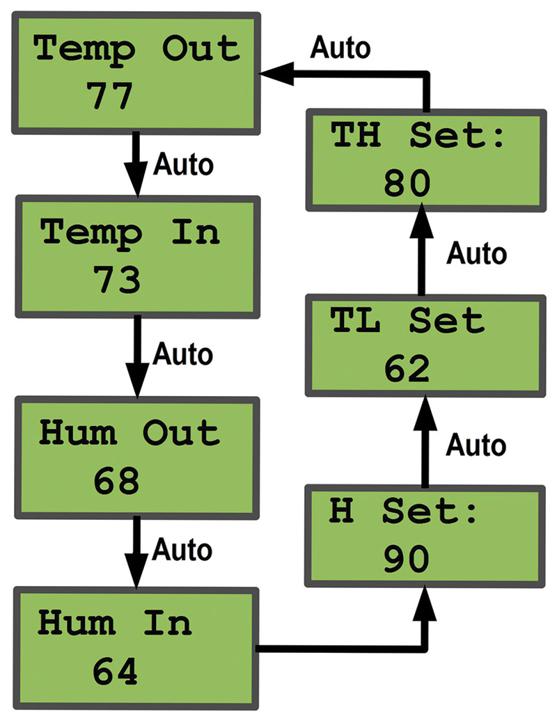
FIGURE 3. Idle mode.
This will put the application into the menu mode:
mt_printPM(tempOut,0,0);<br />
    mt_print8BitNumber(tempOutdoor,0,1);<br />
    if(checkKeyDelay(IDLEDELAY)) return(1);
The loop() calls the idle() function that then runs through all of the functions to display the idle information. It prints the data name on the first line; the data value on the second line; then it calls checkKeyDelay(IDLEDELAY) — the function that checks the key while also delaying for the indicated time, allowing the LCD to display the data for the indicated time. If no key is pressed, then the next set of data is displayed and the buttons checked, and so on until either a key is detected or the data is all displayed. If no key is detected, then the function returns 0 to the loop which runs the idle() function again.
If a key is detected, the idle() function returns 1 and the loop checks to see if there really is a new key available. If the button was CTR, the program runs the menu() function that lets the user input the temperature and humidity settings.
The Menu Mode
One really great thing about the Arduino handheld prototyper is that it provides the Arduino with an LCD for output and pushbutton keys for input — both accessible via two pins on the I2C bus. You have a library of functions that makes using the LCD and the pushbutton keys a breeze. That said, sometimes the logic for getting user input from the keys and showing data to the user can be a bit of a pain. Not only is the logic tedious, but since you only have two lines with eight characters each and five pushbuttons, you have to think about the best way to show the user what is going on using the minimal characters and keys available.
We’ve all messed with TV remotes and have a good idea of how cryptic these limited systems can sometimes be, but we also know this is an inexpensive way to do things. After all, we could just use a PC if we don’t mind the expense.
Typically to use these limited systems, we have some sort of menu structure where the user can use the keys to scroll through text options shown on the LCD and then select the desired action. For the fresh air controller, the actions are fortunately few and simple. We want the user to be able to input the settings for the high and low temperatures and the humidity that the Arduino can compare to the indoor and outdoor sensor readings to decide whether to turn the attic fan on or off. Let’s look at the menu() function:
void menu()<br />
{   <br />
 <br />
  uint8_t inMenu = 1;  <br />
  uint8_t key = newKey;<br />
 <br />
  mt_print(“Move Key”,0,0);<br />
  mt_print(“Up or Dn”,0,1);<br />
  delay(500);<br />
  showSelection(0);<br />
  selection = 0;<br />
 <br />
  while(inMenu)<br />
  {<br />
    if(checkKeyDelay(250))<br />
    {<br />
      checkKey = 0;<br />
      if(newKey)<br />
      {<br />
        if( (newKey == CTR) || (newKey == RGT)<br />
        )// Exit the menu<br />
        {<br />
          inMenu = 0;<br />
        }<br />
        else if(newKey == UP)<br />
        // Scroll up through menu<br />
        {<br />
          if(selection > 0)selection—;<br />
          showSelection(selection);<br />
        }<br />
        else if(newKey == DWN)<br />
        // Scroll down thru menu<br />
        {<br />
          if(selection == SELECTIONS) return;<br />
          if(selection < SELECTIONS)<br />
          selection++;<br />
          showSelection(selection);<br />
        }<br />
        else if(newKey == LFT)<br />
        // Yes, select the current menu item.<br />
        {<br />
          if(selection == 0) doSetTempHigh();<br />
          else if (selection ==<br />
          1)doSetTempLow();<br />
          else if (selection ==<br />
          2)doSetHumidity();<br />
          else // something is wrong<br />
          {<br />
             selection = 0;<br />
             break;<br />
          }<br />
          showSelection(0);<br />
        }<br />
        <br />
        newKey = 0;<br />
      }<br />
    }<br />
  }  <br />
}
When the function first starts, it sets the inMenu variable to 1 so the while loop will continue to look at keys until it gets either CTR or RGT which will tell it to exit the function. It then takes a second to tell the user to move the keys up or down. Then, it moves to the ‘Set TH’ menu item. This is all illustrated in Figure 4.
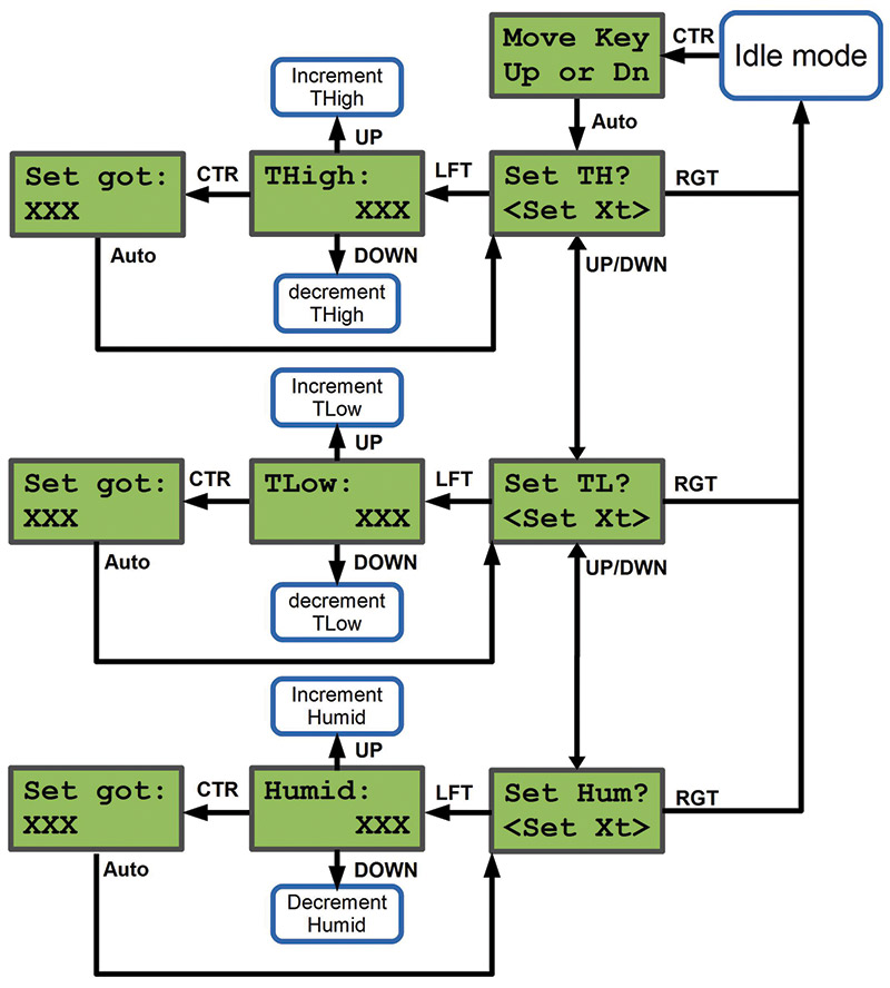
FIGURE 4. Menu mode.
Each menu image is shown in an LCD-like box with arrows showing what happens when you press a key. The ‘Auto’ arrow indicates that the action happens automatically. So, for instance, when you set the high temperature and click CTR, you will see the temperature you set on the LCD. After a moment, the menu returns to the ‘Set TH?’ item where it waits for a button press.
From that menu item, if you press the rightmost button the software returns to the Idle mode. If you press the left key, it goes to the ‘Thigh:’ menu item where you can set the value for the high temperature. If you press the down key, the menu goes to the ‘Set TL?’ (Set Temperature Low) menu item.
This all reads rather complicated, so it is best to do the ‘picture is worth a thousand words’ thing and refer to Figure 4 to see what is really going on. A good exercise is to look at the figure and at the code to see how I’ve implemented this particular menu. My coding style is meant to be educational and may not be the most efficient way to do this, but it is the clearest to me. This should help you understand the style of menu design and programming so that you can follow the method and create your own menus.
The menu calls the showSelection function to write the indicated selection to the LCD:
void showSelection(uint8_t selected)<br />
{<br />
  // Show selected query<br />
  if(selected == SETTH)<br />
  {<br />
    mt_printPM(setTHigh,0,0);   <br />
  }<br />
  else if (selected == SETTL)<br />
  {<br />
    mt_printPM(setTLow,0,0);   <br />
  }<br />
  else if (selected == SETHUM)<br />
  {<br />
    mt_printPM(setHumid,0,0);<br />
  }<br />
  else // something is wrong<br />
  {<br />
    mt_print(“????????”,0,0);<br />
    delay(1000);<br />
    return;<br />
  }<br />
 <br />
  // See if the user wants to set this<br />
  // value<br />
  mt_printPM(yes,0,1);  <br />
}
Notice this has nothing to do with what the Arduino does with the selected item, other than display the selection on the LCD. The work indicated by the selection is done in the menu function under the LFT key part. There — depending on the selection — the working function is called. For example, the doSetHighTemperature() function follows:
void doSetTempHigh()<br />
{<br />
  setTempHigh = mt_get8BitNumber<br />
  (“THigh:”,0);<br />
 <br />
  mt_print(“STH got:”,0,0);<br />
  mt_print8BitNumber(setTempHigh,0,1);<br />
  delay(1000);<br />
}
In this function, the I2C mini terminal is instructed to get an eight-bit number using the second line, and to print “Thigh:” in the first line. The returned value is placed in the setTempHigh variable; then, the LCD is told to print the value it got, wait a second, and return. Again, this is a good time to look at Figure 4 and follow the code to see what is happening.
How It Controls the Fan
Last month, we looked at the algorithm used to turn the fan on or off based on the indoor and outdoor temperature and humidity, based on user input set points. The Idle routine checks the sensors periodically by calling the checkSensors() function we saw last month, then based on the results of the algorithm sets the fanState variable to either 0 or 1. This value is used in the setFan() function that follows:
// Turn the fan on or off<br />
void setFan(uint8_t state)<br />
{<br />
  if(fanState == 1)// turn it on<br />
  {<br />
    digitalWrite(fanPin,HIGH);<br />
    // Set pin to Vcc<br />
  }<br />
  else // turn it off<br />
  {<br />
    digitalWrite(fanPin,LOW);<br />
    // Set pin to ground   <br />
  }  <br />
}
This results in the fanPin being set either high (+5) or low (GND). As you can well imagine, the Arduino isn’t able to supply much +5 volt current to actually run a fan. You have to use this pin to signal an external device — some sort of transistor and/or relay arrangement that turns the fan on and off. Since the fan is almost certainly being powered by mains AC current, you must really know what you are doing to accomplish that step without killing somebody or burning down your castle. My first recommendation is to thoroughly test your system by turning an LED (a fan substitute) on and off to verify that it is all working properly.
As of this moment, that’s all I’ve got on operating the fan. Next month — assuming everything is working properly — we should have the system fully hooked up and tested. Then, we’ll return to the dangerous stuff. In the meantime, wouldn’t it be useful to record all this data we are collecting on the temperature and the humidity, and when we are turning the fan on and off?
Well, first we will want to know the ‘when’ part by teaching our fresh air controller how to tell time.
Teaching It to Tell Time
Fortunately, we just recently went through a bunch of Workshops where we learned a lot about how to keep dates and time on a computer. This began with the January 2013 Workshop where we started looking at how to use the Arduino proto shield to design and build an alarm clock. We then continued through the April Workshop. You can find excerpts of these on my articles repository at blog.smileymicros.com. You can also purchase the associated Arduino proto shield and/or the proto shield alarm clock kit from the Nuts & Volts webstore.
For this section, I will assume you’ve already reviewed that material and can refer back to it if you have questions.
So, Where Do We Put the Clock?
Good question. The fresh air controller pretty much fills out the Arduino proto shield, so where do we put it? Well, remember those stacking headers? Right! We will stack them. Figure 5 shows the alarm clock circuit built on a proto shield PCB (printed circuit board).
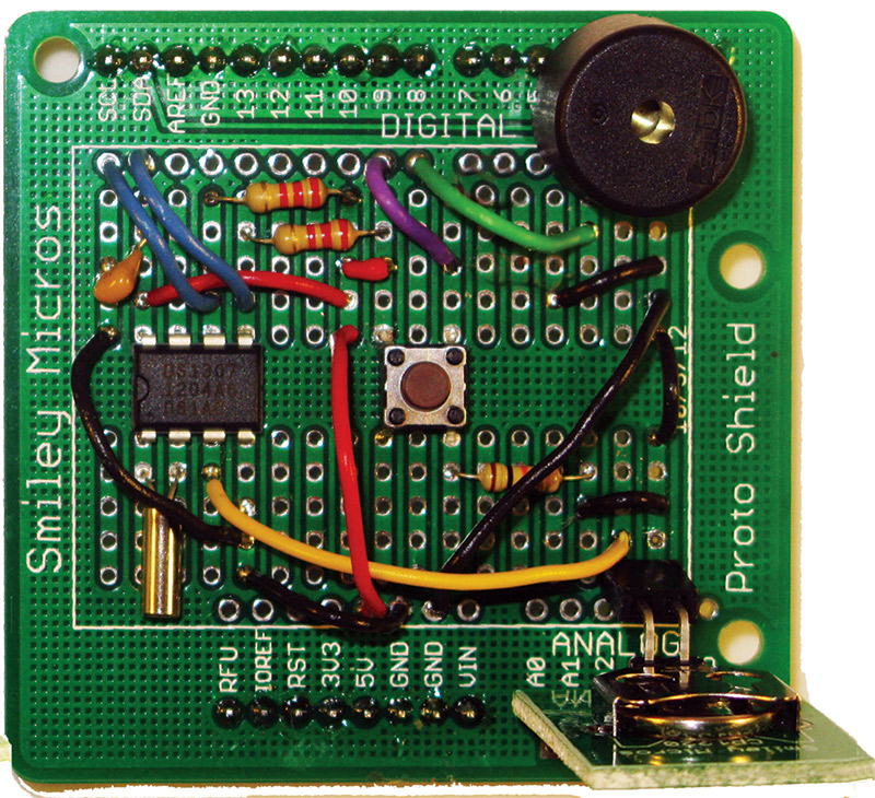
FIGURE 5. Arduino alarm clock.
For the fresh air controller board, you’ll need to add connectors for the DHT22 temperature and humidity sensors so they will have long wires and can be placed off the board. This will make room to stack the alarm clock on top as shown in Figure 6.
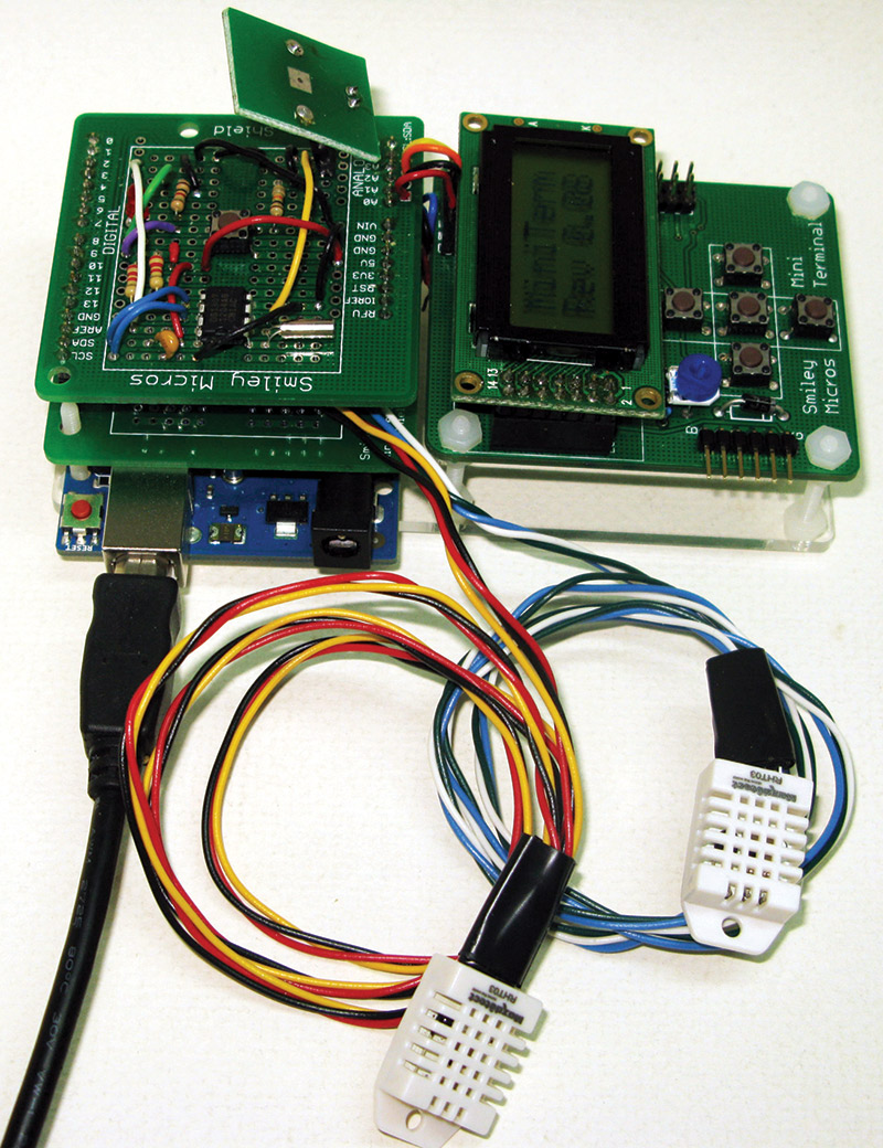
FIGURE 6. Fresh air controller board with alarm clock.
Showing Dates and Times On the LCD
Eight characters by two lines doesn’t give us a lot of space to show dates and times, but it is all we actually need. Both dates and times are traditionally shown with three two-digit numbers separated by two characters: ‘/’ for dates and ‘:’ for time — meaning that eight characters is exactly what we need to show them as we can see in Figure 7.
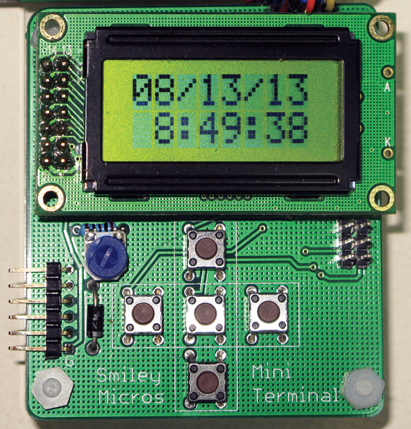
FIGURE 7. Date and time on LCD.
In our earlier Workshops, we saw how to get the date and time from the DS1307 in the DateTime data format. Now, we’ll see how to convert that into characters we can show on the LCD (Figure 7). As usual, there are a couple of unexpected complexities.
The DateTime data type is in military time; that is, hours go from 0 to 23 which is fine if we want to display the time like that, but not if we want to do it the typical way a clock is displayed. We define the variable militaryTime that we set to 1 if we want to display military time, and to 0 if we want the regular time display.
The next complexity is that when we use the itoa() (integer to ASCII) function, we get a buffer with a single character for date and time values less than 10, and two characters for values 10 and above. We have to compensate for this when we display the values, adding a leading 0 to those values from 1 to 9. The following timeToChar function shows how this is done for time. For dates, we use the dateToChar function that is identical in logic, so we won’t show it here:
void timeToChar(char * tim, DateTime myDateTime)<br />
{<br />
 <br />
  char buff[4];<br />
 <br />
  int hour = myDateTime.hour();<br />
 <br />
  if( !militaryTime && (hour >= 12)) hour -= 12;  <br />
 <br />
  // convert the hour<br />
  itoa(hour,buff,10);<br />
  if(hour >= 10)<br />
  {<br />
    tim[0] = buff[0];<br />
    tim[1] = buff[1];<br />
  }<br />
  else<br />
  {<br />
    tim[0] = ‘ ‘;<br />
    tim[1] = buff[0];    <br />
  }<br />
  tim[2] = ‘:’;<br />
  // Convert the minute<br />
  int min = myDateTime.minute();<br />
  itoa(min,buff,10);<br />
  if(min >= 10)<br />
  {<br />
    tim[3] = buff[0];<br />
    tim[4] = buff[1];<br />
  }<br />
  else<br />
  {<br />
    tim[3] = ‘0’;<br />
    tim[4] = buff[0];    <br />
  }<br />
  tim[5] = ‘:’;  <br />
  // Convert the second<br />
  int sec = myDateTime.second();<br />
  itoa(sec,buff,10);<br />
  if(sec >= 10)<br />
  {<br />
    tim[6] = buff[0];<br />
    tim[7] = buff[1];<br />
  }<br />
  else<br />
  {<br />
    tim[6] = ‘0’;<br />
    tim[7] = buff[0];    <br />
  }
  // make the char array a string by terminating<br />
  // it with the NULL ‘\0’ character<br />
  tim[8] = ‘\0’;   <br />
}
The software to use the Arduino alarm clock proto shield kit with the I2C mini terminal LCD is in the Arduino sketch textDateTimeLCD which is available along with the fresh air controller at the article link.
Next time, we will put the date and time code into the fresh air controller so that we can see it as part of the idle() function. We will also begin to learn how to record the data and report it out to a PC so that we can graph the results. NV
Downloads
October2013_SmileyWorkshop63
Alarm Clock and Fresh Air Controller Code