The article, “Build the IoT Sump Pump (or Pretty Much Anything IoT)” generated curiosity about some of the tools utilized to create the device. It’s time to ready Player 2 and penetrate deeper into the utilization of some of the software and hardware features that come with CC3200 Launchpad and Code Composer Studio (CCS).
We will demonstrate step-by-step:
- CCS installation and setup
- How to use the temperature sensor on the CC3200 LaunchPad
- How to adopt a third-party project to work with your environment
- How to upload your code to the external Flash memory
CCS Installation and Setup
For this step, you will need to download CCS for your OS from http://processors.wiki.ti.com/index.php/Download_CCS. We chose Windows Offline Installer for this article. First, unzip the file, run setup, and choose the default install folder (c:\ti). You’ll then be asked to select your processor support. Choose CC32xx Wireless MCUs as shown in Figure 1 and then go to the next step.
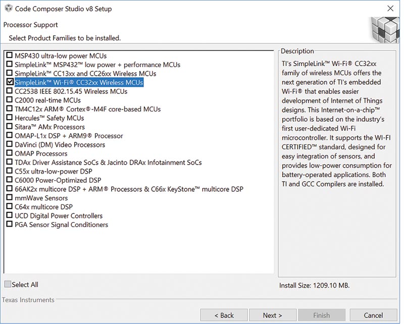
FIGURE 1. CCS processor support.
Keep selected debug probes by default and click Finish. Once installation is complete, click on Finish again and Code Composer Studio v8 should start up. It will ask you to select the Workspace directory.
For this demonstration, we left the default and clicked Launch. At this point, CCS will display the Getting Started tab and is ready for use. However, before we start using it, we need to get a few more items.
Next, we’ll download CC3200SDK from www.ti.com/tool/cc3200sdk.
First, we used Windows Installer for CC3200SDK. Second, we used Service Pack Installer for CC3200SDK. To be able to download these files, you will have to register with Texas Instruments (TI) by creating an account and logging into that account. The software is free.
Once these files are downloaded, run the installer and select the default installation directory (c:\ti).
The last item required is the programming utility UniFlash 3.4.1. Go to www.ti.com/tool/uniflash and make sure you download v3.4.1 with support for CC3200 (the offline installer used for this article). Again, you will need your account with TI to be able to get this free utility. Once downloaded, unzip and run the setup file.
If you have Windows 10, you’ll need to run this setup file in Windows Compatibility Mode. We allowed Windows to automatically select compatibility and it picked Windows 8 mode.
Select the default installation directory (c:\ti\unflash_3.4). On the Select Components menu window, all boxes are checked by default. Keep these defaults and go to the next menu. On the Select Debug Probes menu, no boxes should be selected. Select Next and Finish.
Once installation is complete, let it launch and make sure UniFlash starts up. We have now achieved CCS installation and setup! Figure 2 is what the installation directory should look like once everything is installed.

FIGURE 2. CCS, SDK, and UniFlash home directory.
Temperature Sensor on the CC3200 LaunchPad
We’ll use one of the SDK examples to demonstrate how to use CCS to edit, compile, and run programs on CC3200. Go to C:\ti\CC3200SDK_1.3.0\cc3200-sdk directory. In the ..\docs folder, you’ll find numerous documentation and user manuals. All of the examples are documented and their pdfs are located here as well under the ..\examples directory. The temperature sensor example we’ll use is documented in the CC32xx I2C Application.pdf.
This example demonstrates how to access and read the onboard temperature sensor and accelerometer via an I2C bus. We’ll cover the details of accessing and reading the temperature sensor but accomplishing the same for the accelerometer follows a similar procedure.
In the ..\hardware folder, you’ll find the necessary schematics. Sheet 4 contains the temperature sensor. Refer to Figure 3.

FIGURE 3. TMP006 temperature sensor.
I2C SCL and SDA are on pins CC_GPIO_10 and CC_GPI_11, respectively, so you need to make sure the jumpers J2 and J3 are put in place. The sensor address pins are configured for the 0x41 I2C address.
Now it’s time to fire up CCS. You can close the Getting Started tab. Click on the Open Perspective button (see Figure 4) located in the upper right corner.

FIGURE 4. Open Perspective.
A menu will pop up with a choice of different views. We mostly switch between Edit and Debug views. Typically, CCS switches automatically. However, if you would like to go back to edit mode, select CCS Edit or CCS Simple as shown in Figure 5.

FIGURE 5. Open Perspective dialog.
To demonstrate this feature, we’ll do an example. Go to Project → Import CCS Projects... First, the Import Wizard will open up. Click on the Browse button and navigate to i2c_demo in the ..\example folder. Hit Finish. Refer to Figure 6.

FIGURE 6. Import example.
Go to View and select Project Explorer. Once Project Explorer pops open, you should see the i2c_demo folder. Expand it to see project files and double-click on main.c. Now, go to Open Perspective (from Figure 4 above) and select CCS Simple. You should have a display resembling Figure 7.
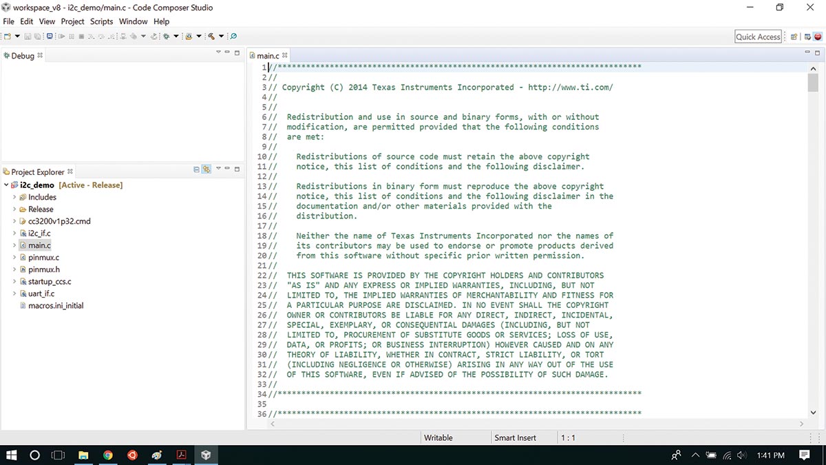
FIGURE 7. CCS Simple.
To clear your workspace, minimize the windows that you no longer need. Also, move and arrange windows for ease of use. Once your screen is organized to your satisfaction, you can begin to edit source files and compile.
This example should compile straight out of the box. However, before we proceed, we should check the project properties and make sure they are appropriate for our demonstration. These projects are a carryover through many CCS releases and sometimes adjustments are needed. Following are the changes we had to make to compile CC3200_SDK v1.3.0 i2c_demo under CCS v8.
Right-click on the project name in the Project Explorer and select Properties. Select the General tab and make sure the latest compiler version is selected; see Figure 8.

FIGURE 8. Compiler version.
Now, select the ARM Compiler tab and if flag --float_support=fpalib is set, click on Edit Flags and change fpalib to none (Figure 9). Click OK, Apply, and Close.
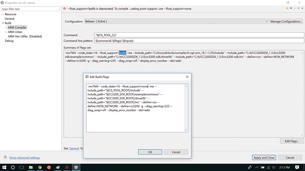
FIGURE 9. Compiler flags.
Go to Project and click on Build Project. The console will open and if successfully compiled, you should get the confirmation “Build Finished” as seen in Figure 10.
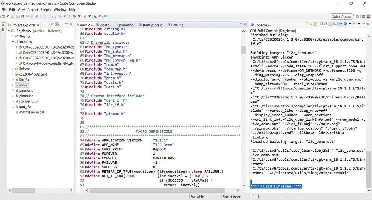
FIGURE 10. Build finished.
Before we proceed with the i2c_demo, let’s explore what this code does.
The application communicates with the user (Terminal Emulator) over UART. It accepts commands to read/write registers on a specified I2C device and displays results on a terminal.
For Terminal Emulator, we used the free application PuTTY. The source code of interest is in the following files:
Main.c - Initializes the board, reads commands via UART, processes I2C commands, writes results to UART.
i2c_if.c/uart_if.c - I2C/UART interface API wrapper that calls driverlib low level functions to open, close, read, and write peripheral.
Pinmux.c - Configures pins and peripherals.
Unpack your CC3200, remove the jumper on header P1 between Vcc and pin P58 if installed, and make sure jumpers J2 and J3 are populated. Connect your LaunchPad to your PC, and the onboard LEDs will come to life.
In CCS under View, select Other. A new menu pops up. Type “target” in the search box and select Target Configurations as shown in Figure 11.

FIGURE 11. Select Target Configurations.
Right-click on User Defined and select Import Target Configurations. Navigate to C:\ti\CC3200SDK_1.3.0\cc3200-sdk\tools\ccs_patch and select CC3200.ccxml as shown in Figure 12. If asked, choose to copy files.

FIGURE 12. Import Target Configurations.
Click on the green bug button on the toolbar to start the debug session. Debugger will start up and if everything loads correctly, you should see the Stellaris In-Circuit Debug Interface. Refer to Figure 13.

FIGURE 13. Stellaris In-Circuit Debug Interface.
Right-click on the In-Circuit Debug Interface in the Debug window and select Connect Target. You are now connected with the target and the target is suspended. Open Debug Perspective and you should see a display similar to what is in Figure 14.

FIGURE 14. Debug perspective.
Next, we need to load the program. Go to Run and select Load and Load Program. You need to specify the .out file that’s located in your Workspace folder. If you selected all default options during installation, it should resemble Figure 15.

FIGURE 15. Load program.
Click OK. Now the program is loaded in RAM, the target initialized, the PC points to main, and all is ready to run.
Next, you need to open your Terminal Emulator. Go to Windows Device Manager and expand Ports. This will show what COM port LaunchPad is connected to. In this case, it was COM4 (Figure 16).

FIGURE 16. COM port.
Now, start up PuTTY. In the category window, select Serial and set it up as in Figure 17 and click Open.

FIGURE 17. PuTTY configuration.
The PuTTY terminal should open a blank terminal screen. In CCS, hit F8 to run the program. The terminal will come alive and after printing out the title, command usage, and parameters, you’ll see a cursor waiting for a command to be entered (Figure 18).

FIGURE 18. PuTTY terminal.
In this example, we want to read the TMP006 ambient temperature register. We can use the readreg command. We need to give it TMP006 I2C address 0x41 and a pointer to the temperature register. From the TMP006 datasheet, the pointer register value is 0x01. Then, we specify how many bytes we want to read.
As you can see in Figure 18, the command returned two bytes: 0x0B and 0x90.
To calculate the temperature in Celsius, we right-shift this number by 2, convert it to a decimal, and divide by 32:
0x0B90 => 0000 1011 1001 0000 > 2 = 0000 0010 1110 0100 = 740(10)
740 / 32 = 23.125 deg C
We heated up LaunchPad using a hair dryer and did the register read again. The board returned 0x1AFC which converts to 53.9°C.
cmd#readreg 0x41 0x01 2
I2C Read From address complete Read contents
0x1a, 0xfc,
Conclusion
The IoT sump pump device design article mentioned earlier initiated several requests for additional details. So far, we’ve explained CCS installation and set-up, and how to use the temperature sensor on the CC3200 LaunchPad.
Stay tuned for Part 2 as we further explore two more items of the device design: How to adopt a third-party project to work with your environment; and how to upload your code to the external Flash memory. NV