My article, “Build the IoT Sump Pump (or Pretty Much Anything IoT)” generated curiosity about some of the tools utilized to create the device. It’s time to ready Player 2 and penetrate deeper into the utilization of some of the software and hardware features that come with CC3200 Launchpad and Code Composer Studio (CCS).
With these capabilities, we can further explore two more items of the device design: How to adopt a third-party project to work with your environment; and how to upload your code to the external Flash memory. Here, in Part 2, we will accomplish this in the following four steps:
- Import CCS project
- Modify it to our specifications
- Compile, run, and test project
- Load project to external Flash memory
We’ll start with the IoT Sump Pump project and modify it to:
- Read the temperature sensor upon every wake-up rather than reading battery voltage.
- Send a text message if the temperature is greater than 50°C.
- We will again use the same wake-up input connected to SW3 on the LaunchPad and simulate real world sensor exercising SW3 instead.
Download, Import, and Compile the IoT Sump Pump Project
First, we need to access the project from GitHub at https://github.com/mkolakovic/IOTSumpPump. Select the Clone or download button and Download ZIP; see Figure 1. Or, you can get the zip file from the article downloads.
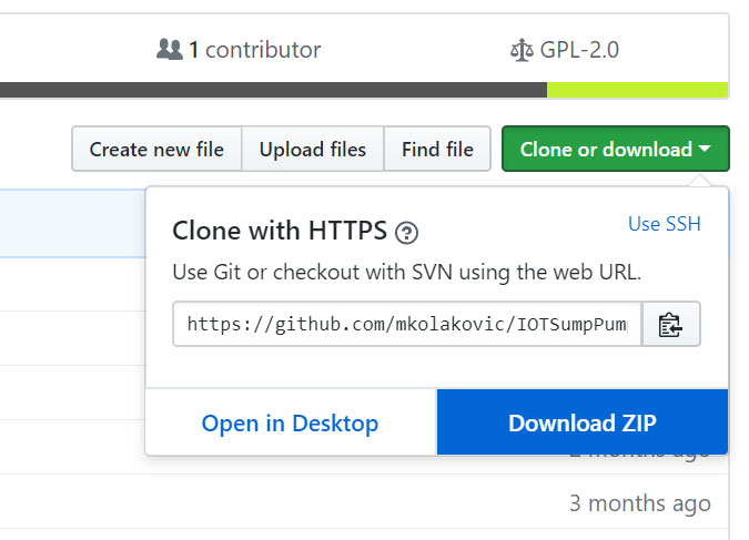
FIGURE 1. Download the project.
Unzip the archive and start your CCS. Go to Project -> Import CCS Projects. First, the Import Wizard will open up. Click on the Browse button to search the directory where you extracted the archive you downloaded. Check the Copy projects into workspace box. Refer to Figure 2.
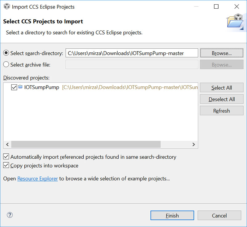
FIGURE 2. Import the project.
Click Finish, then after a few seconds, you should see IOTSumpPump project in the CCS Project Explorer. Click on it to make it an Active project. To rename the project, click F2 and a dialog will open up. Enter a new name such as “IoT_NV_Demo” and click OK (do not use the ‘&’ character in the project name). In CCS Project Explorer, the name has changed. Click on the new project name to make it Active.
Depending on your tolerance for tedious tasks, things are about to get painful. We now have to make changes to the project properties to make the project work within our environment. The original project was created on a Linux machine and all the files and utilities referenced are under different directories. We have to change all that with precision in order for the project to compile.
To open properties, click Alt+Enter. The first thing you’ll notice when the Properties dialog opens is that Compiler Version has a little red box by it. Expand the Compiler Version selection and select the latest version TI v18.1.1.LTS. Just like we did in Part 1, select the ARM Compiler tab, and if flag --float_support=fpalib is set, click on Edit Flags and change fpalib to none. Or, you could accomplish the same by clicking on the Processor Options under the ARM Compiler option and choose “none” from the floating-point support selection menu.
Now, in the Properties dialog left pane, expand Resources and click on Linked Resources.
On the right side, click the Path Variables tab. You’ll notice some variables have their paths defined in Unix fashion (there is no C:/). All these variables must be remapped.
In this case, the “/home/mirza/ti/CC3200SDK_1.2.0” part of the path string should be replaced with “C:\ti\CC3200SDK_1.3.0” which is the location where you installed the TI tools and SDK in the first part. Click on the variable you want remapped and then click the Edit button. In the Edit Variable dialog Location box, you can manually edit the path, or you can use buttons on the left to navigate to it (Figure 3).

FIGURE 3. Edit the path variable.
Next, in the Properties dialog left pane, click on CCS Build. In the right dialog window, click on the Variables tab. Select the “Show system variables” box. If any of these still use the UNIX style path, then remap them; see Figure 4.
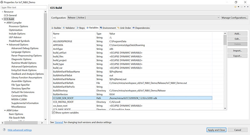
FIGURE 4. Show system variables.
Double-click on the path you want to change and edit the string in the popped-up dialog. It should look like Figure 5. Click OK, Apply, and Close.
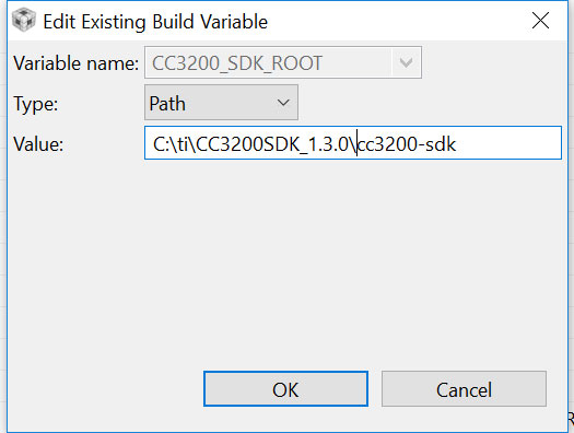
FIGURE 5. Edit the path string.
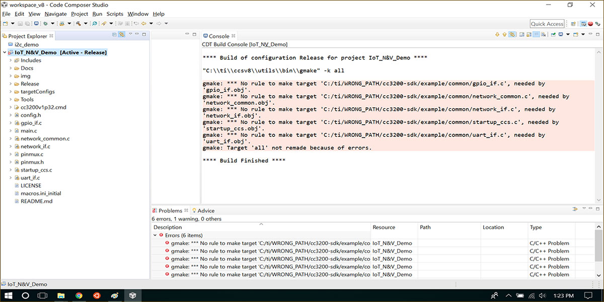
We are now ready to compile! Click the hammer icon on the Toolbar and the project will build. If you got all those properties correct, you should see “**** Build Finished ****” in the output console. If not, check what the compiler is complaining about and go back a few steps, fix it, and recompile until you have no compile errors. Your screen should end up looking like Figure 6.

FIGURE 6. Compile errors due to bad path variable. Easily fixed in project properties.
Modify the Project to Use the Onboard Temperature Sensor
Like we saw in Part 1, the temperature sensor is accessed via I2C. The first thing we need to do is to add the I2C interface to our project.
Right-click on the project in Project Explorer and select Add Files as in Figure 7.
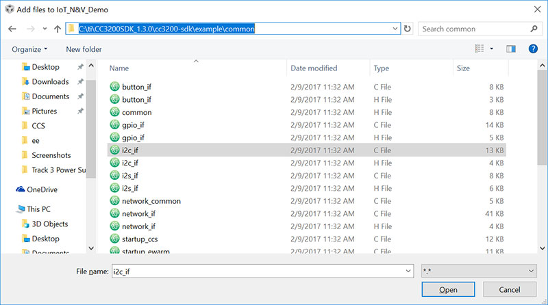
FIGURE 7. Add the I2C interface.
Navigate to your SDK directory and under ../example/common, select the i2c_if.c file. Click Open and when asked, choose to “Copy files.”
Now, we need to include this module editing main.c as in Figure 8.
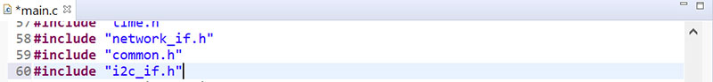
FIGURE 8. Include I2C.
Next, we need to enable peripherals and configure pins. This is done in the pinmux.c file.
Simply use the API provided with SDK to turn the clock on for the peripheral and configure pins for SCL and SCK (Figure 9).
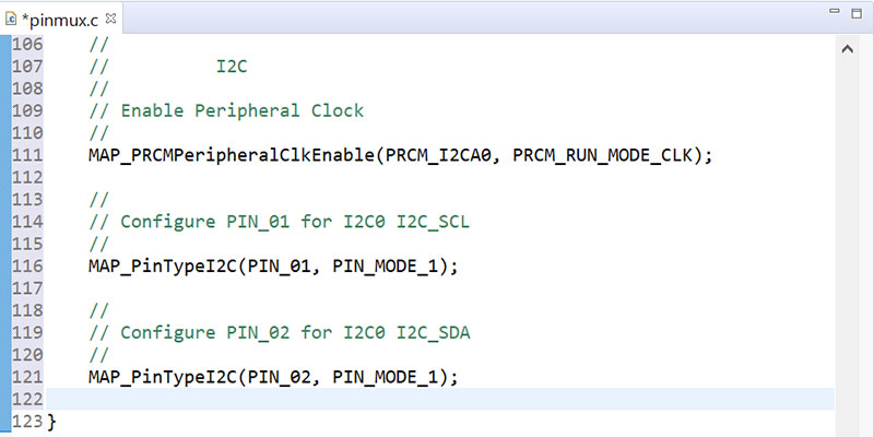
FIGURE 9. Enable peripherals and configure pins.
If you would like to know the details behind API, CC3200 TRM, and the CC3200 Peripheral Driver, the Library User’s Guides are must-reads.
Now, if you look in the i2c_if.c file, you will see a typical programming interface with Open, Close, Read, and Write functions. In the main.c file, go into the BoardInit() function and use I2C_IF_Open() to initialize I2C for Master mode at 400 Kbps. See Figure 10.
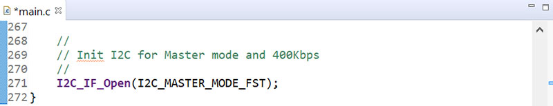
FIGURE 10. Initialize I2C.
At this point, we are all set up as far as hardware is concerned. Since we didn’t modify the board to use a battery monitor for this exercise, we can repurpose the existing VbatMon() function for reading the temperature sensor. Figure 11 is a flowchart that shows how the software works.

FIGURE 11. Software flowchart.
Let’s repurpose VbatMon() now. Find it, rename it to TempMon(), and change return type to float. Gut it and rewrite it using the I2C functions from the interface file. For calculations, see the TMP006 datasheet. Figure 12 shows how it should look when you’re done.
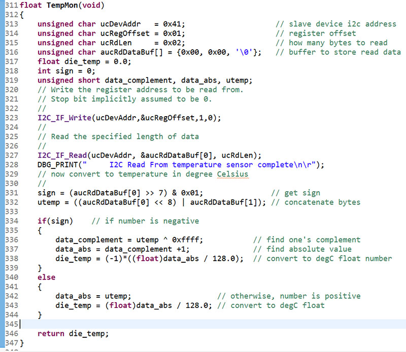
FIGURE 12. Repurpose VbatMon().
Next, in main(), replace references to vbat with temp and change any associated defines at the top of main.c to desired values. Figure 13 shows the part of main() that was changed. Figure 14 shows the new defines.
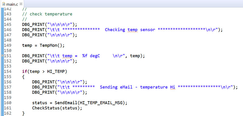
FIGURE 13. Changed main().
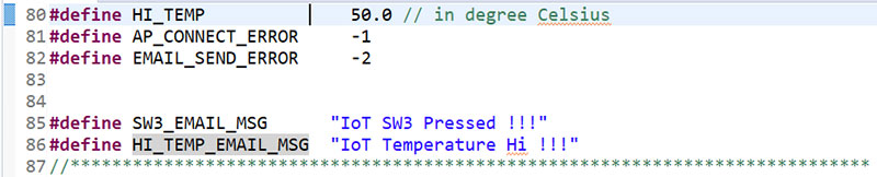
FIGURE 14. New defines.
Arithmetic in the TempMon() is done as described in the TMP006 datasheet, and also verified using data values from the table in the datasheet.
For debugging and testing, you want to load your compiled code in RAM. However, you do not want to let it go to Hibernate. Perhaps use for(;;) or a while(1) loop on the restricted area you want to test out, set the breakpoint, and read your values from the registers when the code hits the breakpoint.
The last thing to do is to set up your wireless Access Point credentials, email account credentials, and your cell phone carrier gateway where you want to send the text messages. All of this is done in the config.h file. See Figure 15 for details.
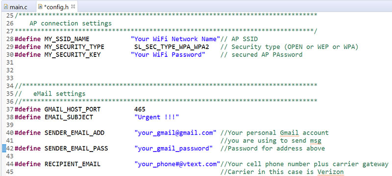
FIGURE 15. Set up access point, email, and cell phone.
Compile, Run, and Test the Project
Now, we’re ready to compile and debug the new project. Click on the hammer icon on the Toolbar to build the project. Once you correct all the typos and errors and the project build is finished, you can connect CC3200 and run/debug it. Before you can run the debugger, you will have to set up Target Configuration like we did in Part 1. There is another way to do this, as well.
Click on the pull-down arrow that is part of the bug icon on the Toolbar and select “Debug Configurations.” Set up Main tab as shown in Figure 16. While you are here, click on the Program tab and make sure “Load Program” is checked. This will help speed up the process. Now, when you click on the bug icon pull-down menu and select CC3200.ccxml, CCS will automatically switch to debug view, connect to the target, and load your code. All you need to do is click on Run(F8).
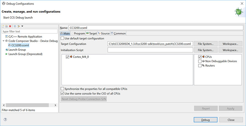
FIGURE 16. Debug configurations.
Again, for debugging, instrument your code so it never reaches Hibernate(). To see all the messages from CC3200 printed via UART, use your favorite terminal emulator. CCS console can also get connected to the UART port for this purpose if you prefer that.
When the code starts executing, you will see debug messages printed on your terminal. It will tell you that the board is initialized, the status of the temperature sensor, the status of SW3, and if it is connecting to AP and sending email. Once it’s done, it will let you know it is gone Hibernating. Refer to Figure 17.
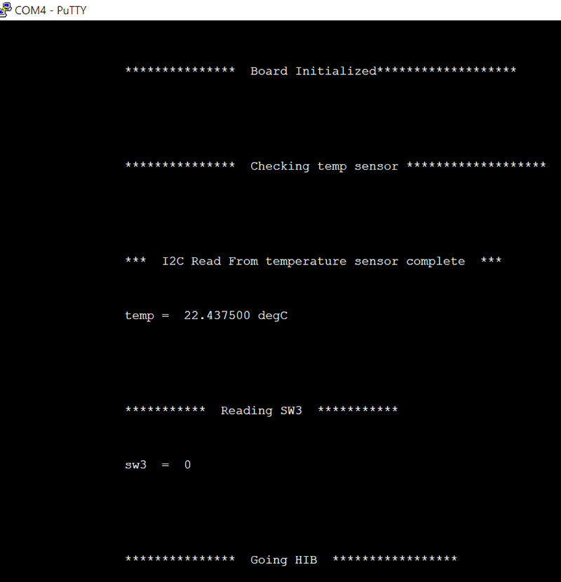
FIGURE 17. Code executing.
If by mistake you let CC3200 hibernate while debugging, you might not be able to re-connect the debugger with it. In this case, power-down CC3200, unplugging the USB cable and trying it all over again.
Load Finished Code to CC3200 NVM
So far, we’ve seen how to upload code to RAM via debugger and run it. But we really need to load code to NVM (non-volatile memory) so it doesn’t get lost on the power cycle. Launchpad provides an external Flash for this purpose. We’ll use the UniFlash utility (see Part 1) to load code to the external Flash memory.
Open UniFlash and click on New Target Configuration, select the CC3x Serial(UART) Interface, and click OK as shown in Figure 18.
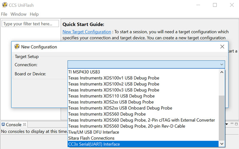
FIGURE 18. CCS UniFlash.
In the CC31xx/CC32xx Flash Setup and Control right window pane, put the correct COM port number in the data field and click on /sys/mcuimg.bin in the left pane as in Figure 19.
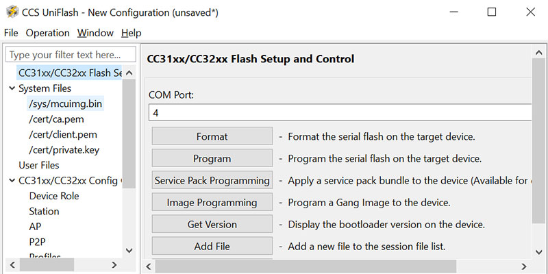
FIGURE 19. Flash setup and control.
Use the Browse button in the right pane to select your project binary and make sure the Erase, Update, and Verify boxes are checked. Refer to Figure 20.
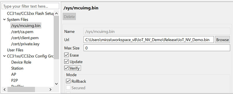
FIGURE 20. Select project binary.
We are now all set to program our code to LaunchPad Flash memory. However, before you can issue the command to program Flash, you must set jumper J15 to ON and reset (SW1) the board. This will reboot the board and the bootloader will get in programming mode (Figure 21).

FIGURE 21. J15.
From the UniFlash menu, select Operation -> Program and the programming will start. You can see the progress in the UniFlash console output. If everything goes as it should, you won’t get any errors and when done, your code will now be in Flash memory.
Take jumper J15 off, open your terminal emulator, and connect it to the COM port. Now, reset LaunchPad using SW1. Your code should be running and you should see all the UART info on your terminal. It will look exactly like we saw it in Figure 17 except it will read your ambient temperature instead of ours.
At this point, the board is hibernating, and is set up to wake up every 18 hours or if SW3 is pressed. Test the board briefly by pressing on SW3 and you should see the board wake up and print all the same info.
You will notice that SW3 reads “0.” This is because the debouncing algorithm is set up to sample the switch for one second and all the samples must read “1” to set the SW3 state to 1.
Now, press SW3 and keep it closed for slightly longer than one second. This will initiate the Wi-Fi connection and send email. Reset the board. Take a hair dryer and heat up the board in the area where the temperature sensor is located (south from SW1). Just briefly close SW3 to wake up the micro (or if you are extremely patient, wait 18 hours for it to wake up itself). If the temperature is greater than 50°C, an email will go out (Figure 22).
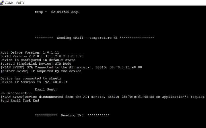
FIGURE 22. High temperature email notification.
You’ll get a text message on your phone as shown in Figure 23.

FIGURE 23. High temperature text message notification.
Ready for Action
With this, we’ve accomplished the goals of this tutorial. We will leave you with a few more words about interfacing LaunchPad with external switches or sensors.
It’s not good practice to have the input go directly to the microcontroller pin, so add an RC filter to the input in case you’re interfacing to external circuitry. We did have an issue with the orginal sump pump project where an EMI blast would couple onto the reed switch wires and wake up the board.
No damage was done, but it was generating false wake-ups. These false wake-ups were dismissed by the debouncing algorithm, but battery life suffered. Adding 10 nF, 100 nF, and 1K ohm in a pi configuration to the input (see Figure 24) indeed did solve the issue. This would have been an appropriate addition in the initial design.
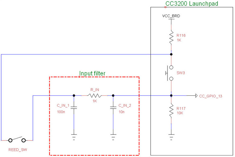
FIGURE 24. Schematic of additions to improve initial design.
We wish you success with your own unique application of the project. NV
Downloads
What’s in the zip?
Source Code
Extra Images
Instructions