My house has a roomy foyer with cathedral ceilings and was built over 30 years ago. When we started thinking about a door bell, we wanted something that would benefit the space and was audible throughout the house. My wife is somewhat hearing challenged, so we kept that in mind while we looked for something. We settled on a NuTone™ chime with four large brass tubular bells, which was presented to us by my parents. It filled all the requirements and more, especially since the sustained melody removed any auditory uncertainty (Did I hear the bell???).
Now, years later, the chime has died and needs replacement. Because of the sentimental value attached to the chime, I started looking at repair options. The bells are struck by four electric solenoids sequenced by a motorized (mechanical) switch mechanism (Figure 1). Unfortunately, the motor was dead (Figure 2).
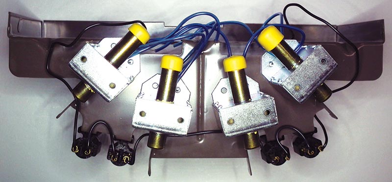
FIGURE 1. Bottom view showing striker solenoids.
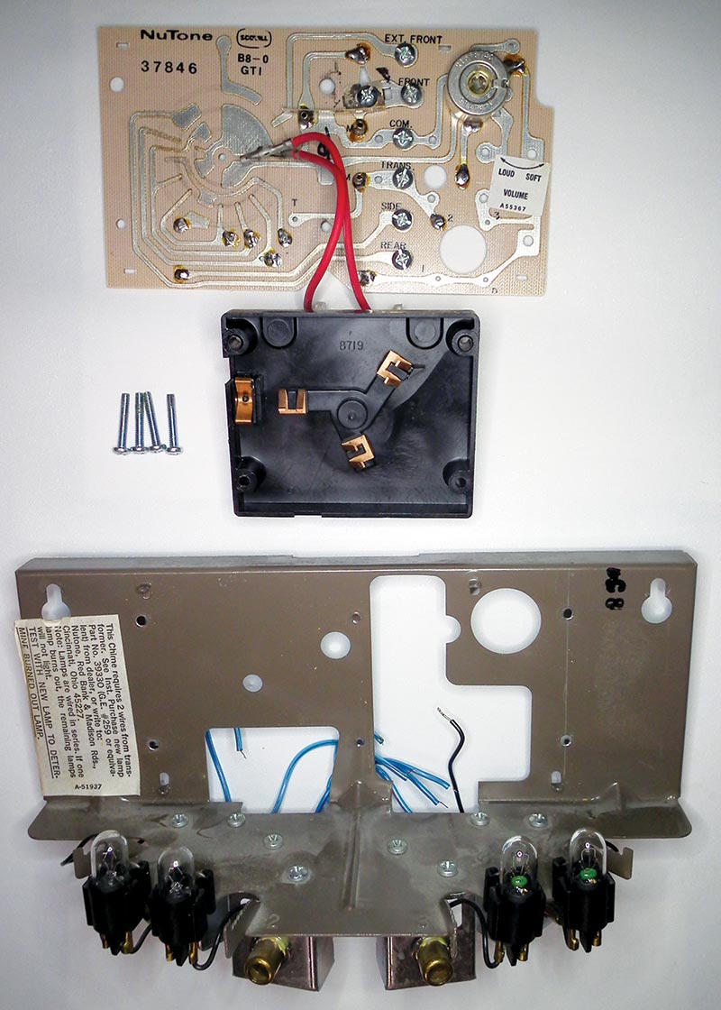
FIGURE 2. Frame, circuit board, and sequencer motor.
Setup
The chime’s electrical setup is basically standard for most door bells: a 16V AC (15VA) transformer feeds the chime, with a standard (LED lighted) pushbutton (Figure 3) at the front and back door. For aesthetic value, behind the cover the chime incorporates panels with four small 6V 1.7W incandescent bulbs in series which provides a pleasant glow at night in the foyer. The front door button activates an eight tone tune; the back door a four tone tune.
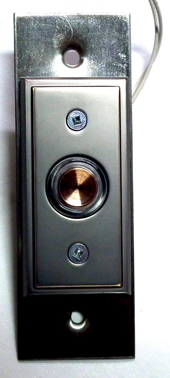
FIGURE 3. Outside lighted button.
The Challenge
I had to save the chime, somehow. Disassembly and removal of a couple dead spiders revealed a remarkably well preserved system.
The chime has four brass tubular bells: 43-27/32”, 37-21/32”, 35-19/32”, and 33-1/4” long; OD is 1” and ID is 0.940”, making the wall 0.03” thick. Each tube has a metal plug and a plastic loop in one end from which it hangs. The solenoids “fire” a plunger (Figure 4) at the top of the tube, producing the sound.
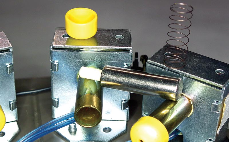
FIGURE 4. Striker solenoid with plunger, end cap, and return spring removed.
In my quest to understand more about the unit, I set out to determine the fundamental frequency of each tube, and therefore its musical tone. I searched the “net” and came up with a number of sites dedicated to wind chimes, but not much on door chimes specifically. Although rather interesting (see sidebar), it was not critical in the rebuild process since we wanted the same melody as before.
Determining resonant frequencies of the bells is actually not a simple matter. Charts (and MUCH more) for wind chimes using open-ended tubes can be found at http://leehite.org/Chimes.htm as well as many other sites.
Unfortunately, most of them cannot be applied to a bell with a closed end. A bell with open ends produces an antinode (the position of maximum displacement in a standing wave system) on both ends, while a tube with a plug in one end will produce a node on the closed end. More on this can be found at www.studyphysics.ca/newnotes/20/unit03_mechanicalwaves/chp141516_waves/lesson51.htm.
Interestingly, some of this sound theory is very similar to antenna properties. Not totally surprising, of course, since both involve waves but in a different frequency range.
Nonetheless, I estimated the notes to be G, C, D, and E (subject to verification). Some time with a small wooden stick and a lot of banging on the bells, we reproduced the original melody (E, C, D, G, pause, G, D, E, C). It was now time to go through my parts bins. I found a small eight-bit PIC (16F627A); it had two eight-bit ports, an internal oscillator option, external interrupt pin, and sleep function. I also found a bunch of small SSRs (Solid-State Relays) of unknown specifications (a ham flea market treasure). No problem!
A bit of empirical testing (abused the crap out of one) proved they could handle way more than what was required here. I had lots of other passive parts in various drawers, so I should be all set. This should be easy!!
Circuit Design Discussion
The PIC and SSRs require 5V; the SSR’s emitter diode can be driven directly from the PIC port (at 20 mA, they must have a limiting resistor or something built in). The SSRs could easily be replaced by miniature five volt relays, but since they were there — plus the fact they operate absolutely noiselessly — it made them a great choice. Most SSRs can only switch AC power, and they do not have an inductive coil (safer for the PIC) like standard relays do.
The supply transformer (in the basement) is rated 16V/15VA, and is permanently wired into the 120V house wiring. In order to keep power consumption down, I decided to go with a switch mode type power supply (Figure 5) since I also planned on replacing the incandescent bulbs with LEDs, but more on that later.
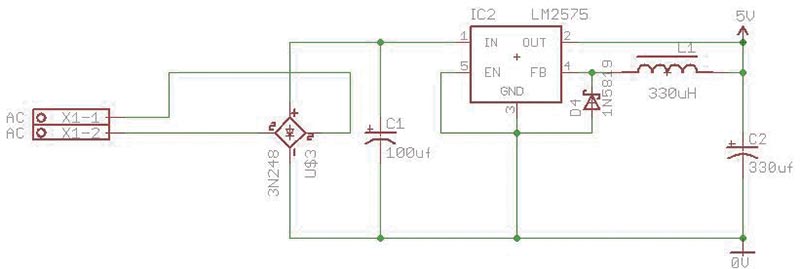
FIGURE 5. Diagram of power regulator.
The LM2575 datasheet recommends a 330 µH inductor, but since we only draw a fraction of the max current, the regulator is happy with the 470 µH inductor. The AC striker solenoids hit best when provided with adequate power, thus additional power conservation during operation was a factor since 15VA is not much to start with.
Next challenge was the buttons. Since the buttons are outside and connect to a sensitive PIC port, static electrical insulation was required. An optocoupler is ideal for that. The port is pulled high by a 9.1K (close enough to 10K; I have a whole spool of them!) resistor, and pulled low (to 0.6V) by the optocoupler. The 3N33 emitter diode has a forward voltage of 1.1V, and a max forward current of 80 mA. The input voltage is limited by a 4.7V zener (1N4732A) and the current by a 120 ohm resistor. The max emitter diode current, therefore, is (4.7-1.1) / 120 = 30 mA — enough to push the output transistor in saturation for the low current required.
Since the power is only half wave rectified (the 1N4001 diode), I included a small electrolytic capacitor (1 µF) and a bleed down resistor (1K) to improve performance of the optocoupler. The current through the zener must therefore be higher than 30 mA for it to be able to maintain its rated 4.7V voltage. When I connected the pushbutton, the chime started ringing steady. What was going on here?
The current drawn by the built-in LED in the button was enough to saturate the optocouplers! A 220 ohm resistor was added to sustain the button LED current, and an additional 8.2V zener (1N4738A) was added to further isolate the optocoupler circuit from the button. A 10 µF capacitor was added to smooth the half wave power.
Let’s look at the (rough) numbers to see if this should work. Refer to Figure 6 for the following description.
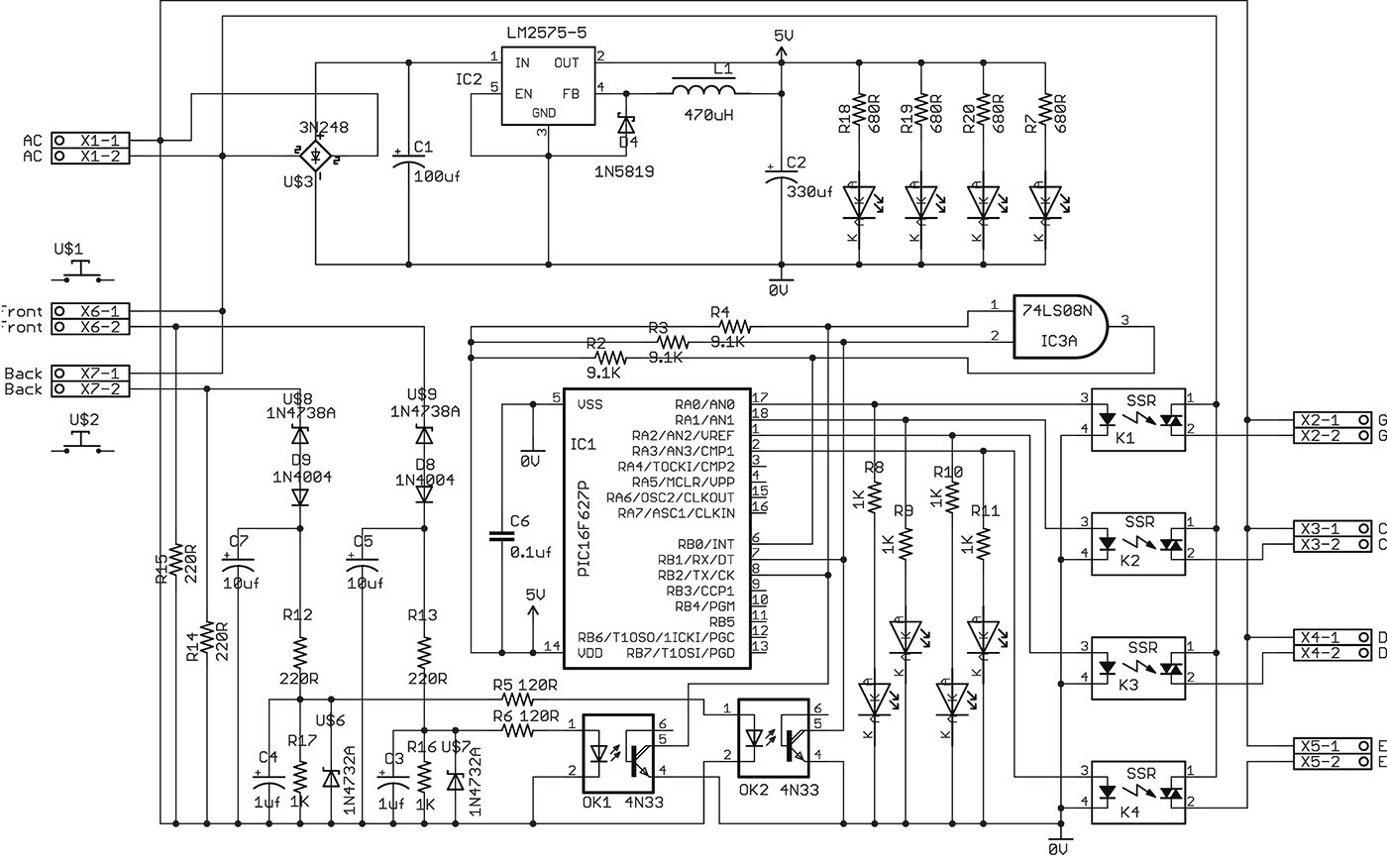
FIGURE 6. Full circuit diagram.
Out of circuit (on the test bench), the lighted button fed with 16V AC and a 220 ohm resistor drew about 30 mA. I’m not sure exactly what is inside the button, but I assume there must be a rectifier and resistor of some sort to provide DC to the LED. This resulted in about 220*0.03 = 6.6V AC to the optocoupler circuit. The 1N4738A zener and the reverse voltage of the 1N4001 (8.2 + 0.7 = 8.9V) ensure that there is now no current flowing in the optocoupler circuit when the button LED is lit.
When the button is pushed, it is shorted and its LED (predictably) extinguishes. We now have 16V AC over the optocoupler circuit. Despite the 10 µF capacitor, there is still a fair bit of ripple in this power line. That’s not a problem, and as such I’m going to ignore that for now (by the time it gets to the optocoupler emitter diode, it is clean enough). To determine our zener current through the 1N4732A diode, we now approximate the following:
(16 * √2) - 8.2 - 0.7 = ~13.7V at the 10 µF capacitor
Therefore, the zener current through the 1N4732A diode is about (13.7 - 4.7) / 220 = 41 mA. Great! That’s 11 mA over our minimum requirement here. The current through the first zener (1N4738A) is now 41 mA, plus the current through the 1K bleed resistor: (4.7 / 1000) + 41 = 45.7 mA.
I’ve got a couple more things to check. Both the zeners are 1W types. Dissipation in the 1N4732A (4.7V zener) is 4.7 * 0.041 = ~0.2W, and for the 1N4738A (8.2V) zener is 8.2 * 0.046 = ~0.38W, so we are well within the 1W limit. The transformer voltage dropped to about 14V (AC) while the strikers are activated, so now we have (14.5 * √2) - 8.2 - 0.7 = ~11.6V at the 10 µF capacitor. Zener current (1N4732A) is now (11.6 - 4.7) / 220 = ~31 mA. That’s enough.
The resistors are 1/2W types, and similar power limit calculations can be done for them. Please remember these are all approximations since I am ignoring capacitor ripple currents, as well as the fact that the power transformer 16V output drops a fair bit when loaded. The objective is to verify that we have reasonable “swing” room in the various sections of the circuit, so it will work as designed.
The PIC
There are always several ways to make something work, and probably the easiest way to detect a button push is to run a scan routine. I decided to use the PIC sleep capability, so I needed an interrupt routine to wake the PIC when a button was pushed. I used the external interrupt on change pin. It can be programmed to trigger on the negative or positive going transition.
Since the pin is held high by the 9.1K resistor and pulled low by the optocoupler, I needed to look for the positive to negative transition. Since I have two individual buttons and only one INT pin, I needed to combine these signals into one, but keep them separate at the same time. I therefore used an AND gate.
The 74LS08N is a quad AND gate; I used only one section (inputs of the unused sections are pulled high). The AND gate will have a high output as long as both inputs are high. Now when a button is pushed, INT goes low, interrupt is set, PIC wakes, looks which button has gone low, and plays the correct tune. When done, the interrupt is cleared, and the PIC returns to sleep.
Circuit Board
This is a one-off project, so nothing too fancy here. The most important thing is probably the switch mode power supply. If building on proto boards, try to keep connections as close as possible to the regulator, since long connections can introduce undesirable oscillations.
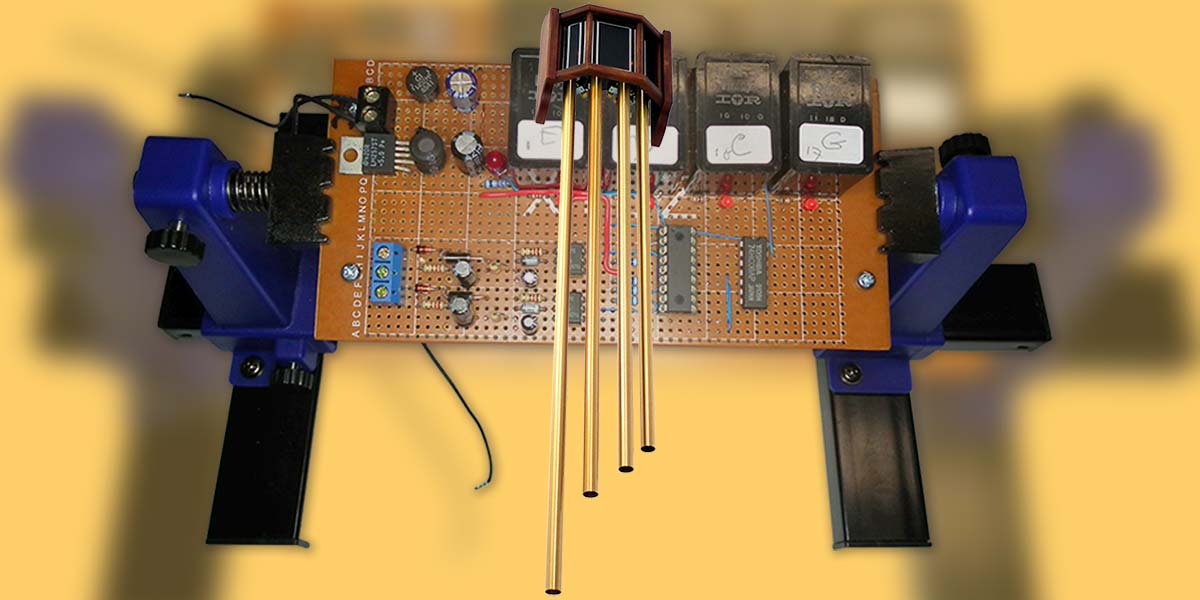
I do not anticipate that many readers will be building one of these, but if you do have a similar chime, they are worth preserving. With that in mind, circuit construction was done on a simple dot type proto board (Figures 7 and 8). Once the extraneous parts were removed from the chime, there was lots of space for the new board. I mounted it on four brass stand-offs.
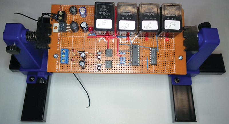
FIGURE 7. New circuit board in assembly stand.
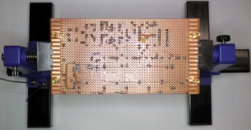
FIGURE 8. Bottom view of new circuit board.
Lights
The chime has four small light bulbs (#259, 6.3V, 1.7W peanut style) wired in series. My original plan was to replace them with LEDs (as shown in the diagram), but I missed the warm glow of the incandescent bulbs!
It also occurred to me that I had never replaced them in the 28 years since we installed the chime, and they were still working when I took the chime down. Let’s see, that’s 29 * 365 * 24 = 254,040 hours of continued operation!
Interestingly, when I checked the original bulbs again during re-assembly, they were all defective. I suppose that the filaments were so brittle that my disturbance shattered them.
If there was ever any doubt that lowering the light bulb voltage extends its life, here is the proof: 16 / (4 * 6.3) * 100 = 63.5% of the rated voltage. I got four new bulbs, and I have my nice glow back.
Final Bell(s)
Well, there you have it. I enjoyed refurbishing this old chime, as well as documenting the process. I hope you enjoyed reading about it, and perhaps it may even inspire someone to tackle a similar project.
I put together a small download package which includes a short video of the chime after refurbishment as well as the firmware for the PIC.
The firmware for this project was written in C, and since my other projects were always done in assembly, this was a first for me there.
The program is very simple and well commented. NV
Downloads
What’s in the zip?
Source Code
Data Sheets
Movie File