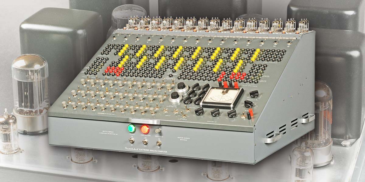
When I first got into electronics in the mid-1950s, I would pour over the Heathkit catalogs and dream about owning a 5” scope. When they came out with the ES-400 Electronic Analog Computer with its 45 vacuum tubes across the top, I wanted one in the worst way. It looked so cool (Figure 1)! And it was only $945. Gulp!
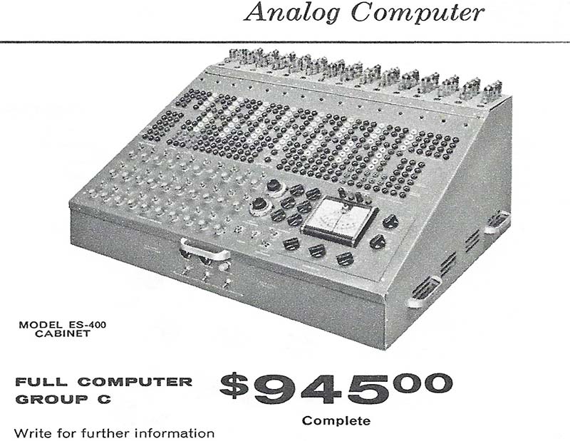
FIGURE 1. Heathkit ES-400 sold from 1956 to 1962. Equivalent to $8,175 in 2019 dollars.
Fast forward six decades. Today, I finally have one in my shop on my bench completely restored! Figure 2 is the proof. It took me eight months of part-time work to restore all 168 pounds. In this article, I would like to share a few of the trials and tribulations I went through to resurrect this beast.
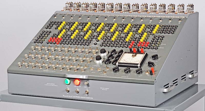
FIGURE 2. The 60 year old computer took eight months of part-time effort to restore.
FREE IS NOT ALWAYS FREE
Several years ago, I restored Heathkit’s smaller analog computer, the EC-1. You may have read about it in the May 2016 issue of Nuts & Volts. Afterwards, I vowed to find and restore my dream computer: the ES-400. Amazingly, a nice gentleman in Northern California heard about my quest and just happened to have one in his storage locker. He said I was welcome to it for free if I would give it a good home. What a laugh!
I’m located in Southern California, so we met up the coast about halfway between us, and made the transfer. Unfortunately, on the trip back down to my shop, I had a major problem. The transmission in my SUV failed and the computer and I shared a tow the final 103 miles — $2,200 later, the SUV was back in operation and the so-called “FREE” computer was safely in my shop. C’est la vie!
SPECIFICATIONS
The “Big Kahuna” had 25 major assemblies containing a total of 73 vacuum tubes and the following specifications:
- Model: ES-400 (sometimes called H-1)
- Original Price: $945 (equivalent 2019 dollars = $8,175)
- Time Period Sold: 1956-1962
- Quantity Sold: Approximately 250-400*
- Weight: 168 pounds
- Dissipation: 450 watts
Assemblies:
- (1) ES-2 Amplifier Power Supply (regulated ±250V at 250 mA, -450V at 50 mA, 6.3VAC at 14.5A)
- (1) ES-50 Reference Power Supply (regulated ±100V)
- (3) ES-100 Initial Condition Power Supply (2x floating 100V, in each supply)
- (1) ES-151 Relay Power Supply (2x 50V)
- (15) ES-201 Operational Amplifier (gain = 50,000, output range ±100V at 10 mA)
- (1) ES-400 Cabinet and Front Panel (364 jacks, 52 switches, 38 pots, 14 connectors, one meter)
- (1) ES-505 Repetitive Oscillator (0.6-6 Hz)
- (1) Sola Voltage Regulator Transformer (250 VA)
- (1) ES-600 Function Generator (optional)
*Estimate by Chuck Penson WA7ZZE, author of Heathkit Test Equipment Products
WHAT WAS I THINKING?
What is that old saying, “be careful what you wish for?” When I finally got the computer in the shop and had a good look at what needed to be done, I wondered about my sanity. Figures 3 and 4 illustrate the as-received condition of the front panel and interior.
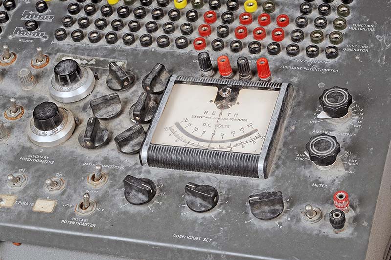
FIGURE 3. The unrestored front panel needed some TLC. Two knobs on the right side were not original.
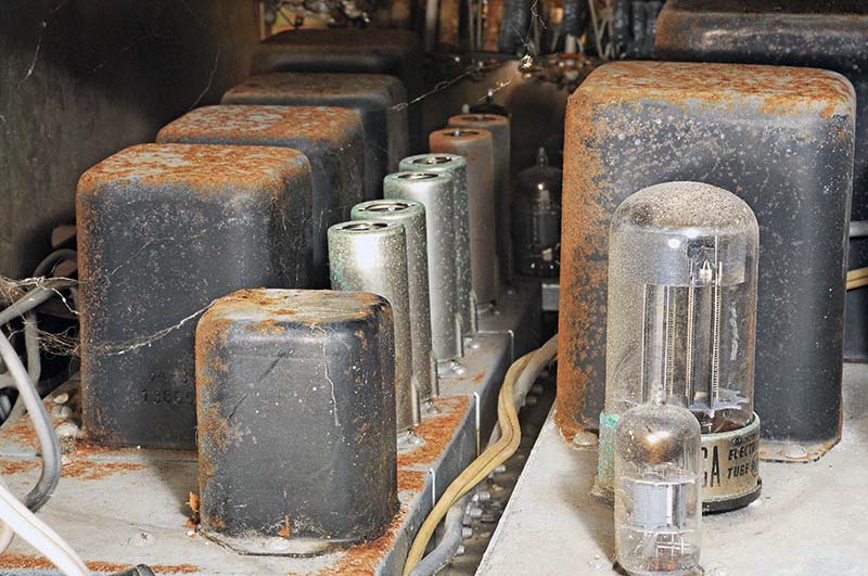
FIGURE 4. The transformers and steel chassis were rusty but not damaged.
The rust on the transformers and chassis inside would be easy to take care of, but what worried me the most was the front panel. There were ugly masking tape labels and grime to remove that could scratch the delicate silk-screened lettering. Not good.
I started by removing all the assemblies (mostly power supplies) from the cabinet. Figure 5 shows me struggling to extract the 43 pound ES-2 amplifier power supply. I then had an idea about how to attack the front panel, which had hundreds of wires and cables connected to it.
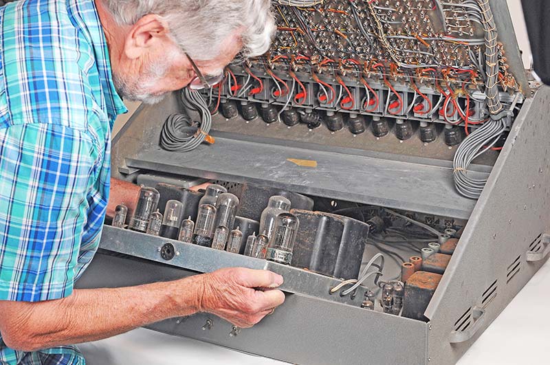
FIGURE 5. I struggled to remove the heavy 43 pound amplifier power supply.
Perhaps I could remove all the pots, switches, and jacks from the rear with the wires still attached, all in one piece as a harness. This technique worked beautifully, although unscrewing 364 banana jacks had me seeing double.
Figure 6 is the harness with its rusty pots and 800 soldered connections.
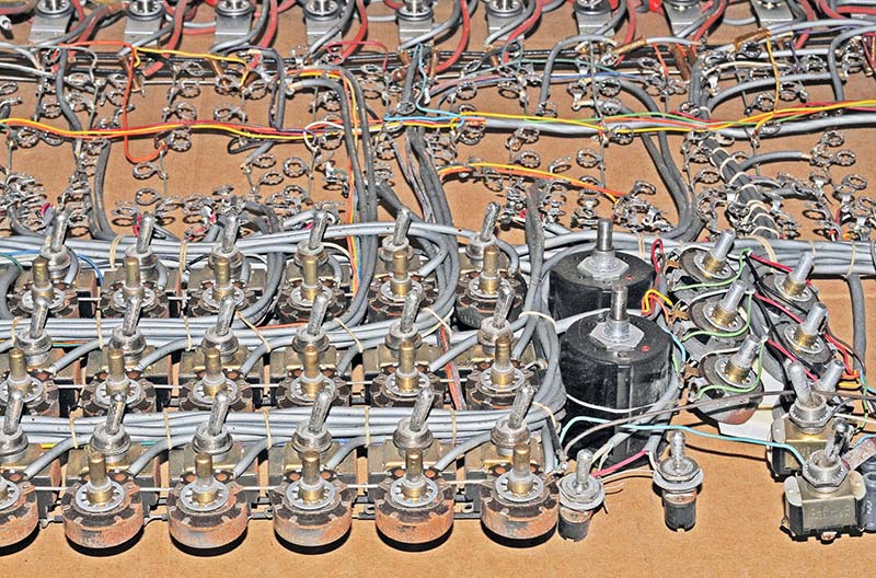
FIGURE 6. The front panel components were removed via the rear as a single harness, in order to clean the front.
ATTACKING THE FRONT PANEL
The bare panel was a mess. The hardest thing was carefully scraping off the masking tape labels. I tried using different tools, but my thumbnails worked best. The old adhesive still left patterns in the panel and there were quite a few tiny pinholes in the gray paint.
So, I tried all kinds of gentle chemicals like 409, Citrus Magic, Goo Gone, lighter fluid, and various alcohols, but none were very effective and some actually attacked the paint. In the end, I had to settle for an “adequate” job on the panel, instead of perfect.
To finish it off, I was advised by a Heathkit restoration expert to vigorously clean the whole panel with Meguiar’s Ultimate Compound, then apply two coats of Meguiar’s Cleaner Wax.
I’ll have to admit the end result was really smooth and looked 200% better. It wasn’t perfect, but for a 62 year old panel it looked pretty darn good. Plus, it was heavy since it was made of steel not aluminum.
Figure 7 shows how it looked after I put it back together. You might compare that with how it looked before in Figure 3. Big difference!
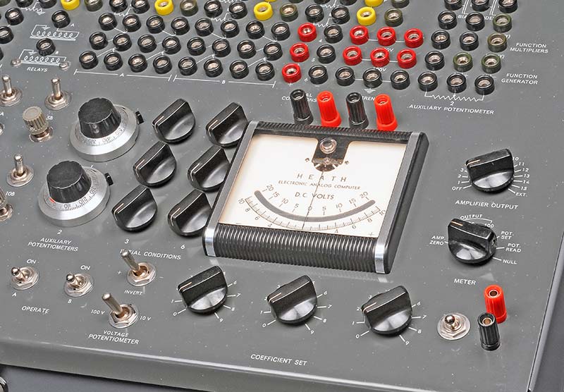
FIGURE 7. The front panel cleaned up nicely compared to Figure 3. All knobs now match.
Also in Figure 3, you might have noticed that the two black knobs on the far right side were not original. I purchased two vintage “for-parts” Heathkit MM-1 VOMs on eBay for $10 and $20 and scavenged their unique Daca-Ware knobs. Later, I found the same knobs on eBay for $3 each.
Oh well.
ES-2 AMPLIFIER POWER SUPPLY GENERATES SMOKE
As you probably know, electrolytic capacitors are prone to drying out over time and reforming them is a technique that only sometimes works. The ES-2 had 16 large axial electrolytics ranging from 20 mfd at 350V to 70 mfd at 350V.
Just to be safe, I replaced them with new ones from Antique Electronic Supply (TubesAndMore.com). I also replaced the smaller caps too. Less chance of problems that way.
It was necessary to take the big power supply completely apart in order to clean and paint the rusty transformers and chokes. Two coats of primer and satin black paint made them look like new. Figure 8 shows the finished unit.
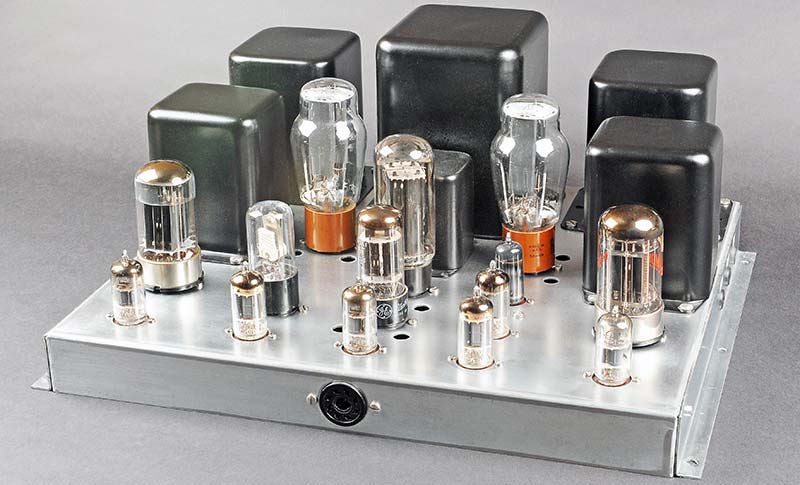
FIGURE 8. The restored amplifier power supply looks almost new. All electrolytics were replaced.
It came out pretty good compared to how it looked in Figures 4 and 5. Reminded me of a stereo Hi-Fi amplifier.
After it was reassembled, I tested the outputs with a bunch of Dale power resistors and expected them to get hot, but not hot enough to MELT MY FAVORITE TEST PROBES!
The problem was that the power supply was temporarily surrounded by three pieces of wood to support it and there wasn’t enough circulation to properly cool it.
After five minutes, it stopped regulating and applied unregulated high voltage to the loads which, in turn, overheated and caused my DVM probes to melt and generate smoke.
Lesson: Give vacuum tube equipment room to breathe or add a fan.
THE AWESOME 15 OP-AMPS ACROSS THE TOP
The (15) ES-201 op-amps took the most time of anything to disassemble, clean, paint, stuff the PCB (printed circuit board), and test. Many of the original 1% resistors were a little corroded and the three tube sockets definitely needed to be replaced with shiny new ones.
So, I carefully unsoldered the components from the PCBs, being careful not to overheat and lift any of the traces. Fortunately, there were only two pads that consistently lifted a bit, but none broke off.
Figure 9 shows a couple of bare boards. I measured the 1% resistors, and most were within spec. I didn’t trust them, however, since there was green copper oxide corrosion on the metal caps at each end.
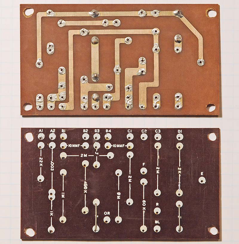
FIGURE 9. Each op-amp had a one-sided phenolic PCB. All parts were replaced.
The carbon resistors were all over the place in value, so they also got the toss along with the capacitors. I figured that installing all new parts would save me headaches down the line.
Figure 10 shows the finished amps, ready to be tested. Figure A at the end of the article is the schematic of one op-amp. The only problem I encountered was that one of the vintage NE-51 neon bulbs wouldn’t light.
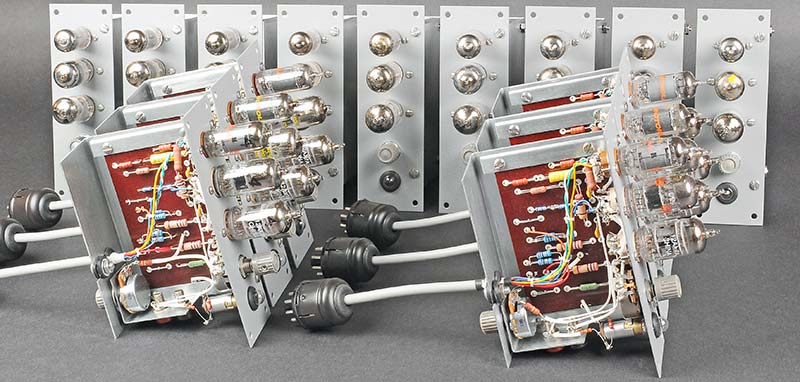
FIGURE 10. The 15 op-amps took what seemed like forever to clean, rebuild, and test.
PROBLEMS, SOLUTIONS, AND ADDITIONS
My goal was to restore everything as close to original as possible, but sometimes changes had to be made. Here are some of the issues I had to deal with.
Problem: No assembly or operation manuals came with the computer.
Solution: Found a set for $50 after a brief search. You gotta love the Internet!
Problem: The interior surfaces of the cabinet panels were not painted originally, and after 60 years they were rusty and looked terrible.
Solution: I had the (eight) 16-ga steel panels sandblasted and powder-coated inside and out with textured gray; cost $180 (see Figure 11). They looked great! I used star lock washers to cut through the paint during reassembly, so all the panels and metal chassis were grounded.
Aside: Electrical ground — which included numerous shielded cables — was completely isolated from chassis ground.
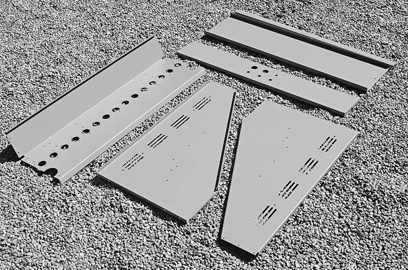
FIGURE 11. A textured gray powder-coat made the steel cabinet panels look great.
Problem: There were NO silkscreened labels on the front power panel or rear connector panel, i.e., the Main Power and HV switches had no ON/OFF labels. Photographs of other vintage ES-400s showed that some of them had numerous labels and others had none. Weird.
Solution: I used Word to regenerate the original labelling and ordered a custom dry transfer sheet from CustomRubOnTransfers.com for $65 (see Figure 12). It turned out really nice!
Drawback: Rubdown letters are not as scratch-resistant as silkscreened versions, even after spraying with clear coat.
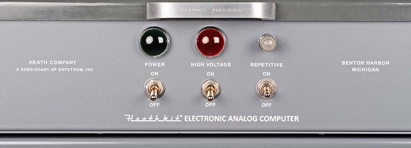
FIGURE 12. A custom dry transfer sheet duplicated the silkscreening on other ES-400s.
Problem: The computer (when received) had a little 12” wooden stick to hold the front panel partially open. When I felt how heavy the steel panel was, I decided that it needed to be firmly supported whenever I stuck my head inside to dress the wires later on. (Would you trust a stick?)
Solution: I added two sturdy locking tip-up support rods to hold it open during restoration and future servicing as seen in Figure 13.
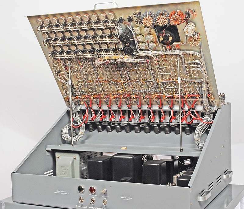
FIGURE 13. Two tilt-up locking rods were added to hold open the heavy front panel.
Problem: Unfortunately, the “free” computer did not include any of the 45 tubes for the 15 op-amps across the top of the cabinet. The 6BQ7As and 6BH6s were pretty reasonable, but the (15) 12AX7s were another story. Some eBay prices were pretty outrageous; $499.99 for a matched pair!!
Solution: Luckily, Chinese 12AX7A tubes were available from TubesAndMore.com for $9.59 each and they worked fine. Refer to Figure 14.
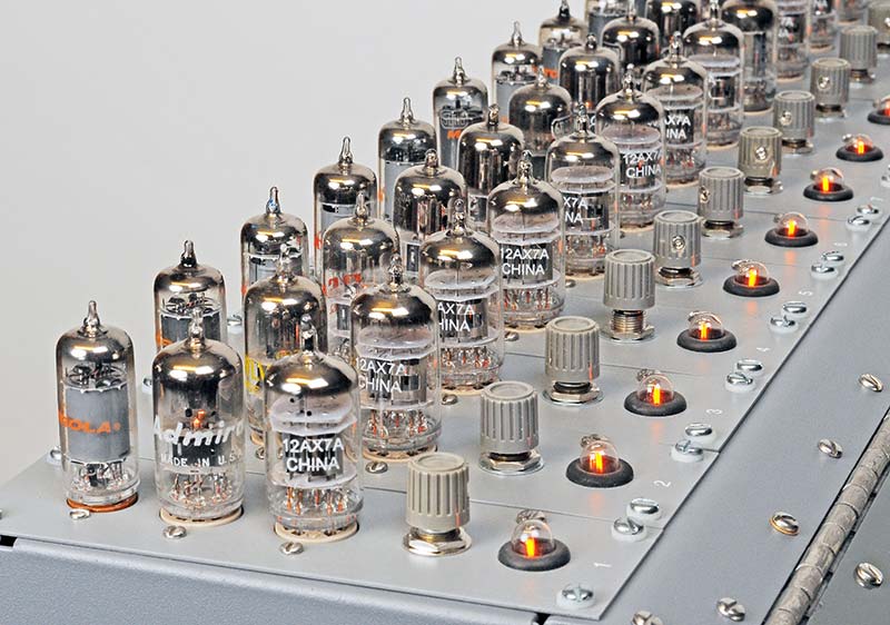
FIGURE 14. These $9.59 Chinese 12AX7As were used because prices of NOS tubes were outrageous.
Problem: All the nuts and bolts were corroded, as were many other electrical components.
Solution: I replaced every nut, bolt, screw, and washer in the entire machine, and also 51 pots, 64 tube sockets, eight toggle switches, 15 octal plugs, and eight power cords. Plus, the countless resistors and capacitors. Whew! Figure 15 shows how clean the interior looked after restoration.

FIGURE 15. The restoration made the interior look new. Note the glowing 5651 regulator.
Problem: Originally, a large VERY RUSTY after-market squirrel cage blower was mounted inside the cabinet to cool the six power supplies.
Solution: Take a look at Figure 16. I mounted two modern axial fans on the rear panel. Sweet! And they sounded good too! I know they aren’t original, but I made that call. Let me know what you think.
Addition: Also in Figure 16, notice the added labels under the 13 Varicon connectors. They were on the custom rubdown sheet too.
Addition: I added an elapsed time meter on the rear panel to measure MTBF. It’s located on the far right of Figure 16.
Addition: I added a three-wire line cord receptacle and fuse holder on the rear for convenience.
Addition: I purchased a custom-fitted gray nylon dust cover for the completed computer from BuyPCSupplies.com for $59. It fits great. See Figure B at the end of the article.
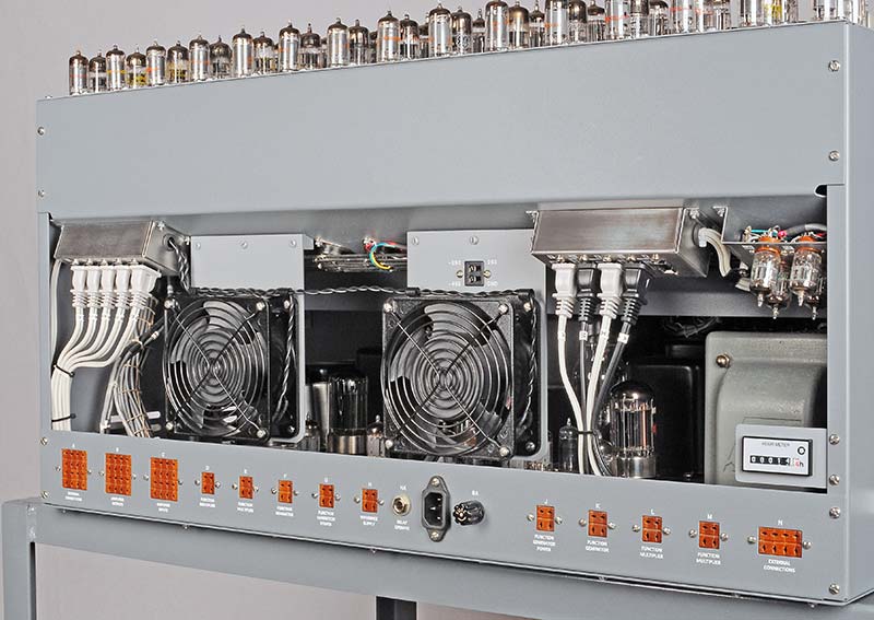
FIGURE 16. Two non-original fans were added to cool the six interior power supplies.
LOADING AN APPLICATION
Once every assembly had been individually tested and installed in the cabinet, it was time to put the whole thing through its paces. Figure 17 is the schematic of the “simulator application” that I loaded in order to test the system. Only nine of the 15 op-amps were required for this app.
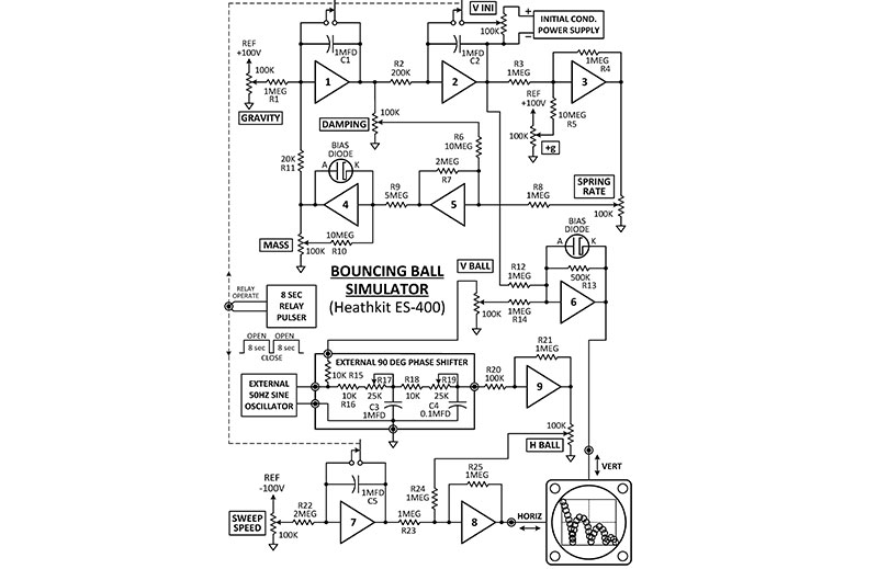
FIGURE 17. A classic analog demo simulates a bouncing rubber ball on the earth or moon.
As you can see in Figure 18, loading an analog computer was a little different from a digital computer.
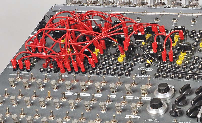
FIGURE 18. The simulation required 35 patch cords and nine of the 15 op-amps.
It involved plugging in 35 banana jumper cords, 20 resistors, and three capacitors. The output was a repeating signal that simulated the action of a falling ball on an XY oscilloscope; refer to Figure 19. Various pots on the front panel controlled the action of the ball.
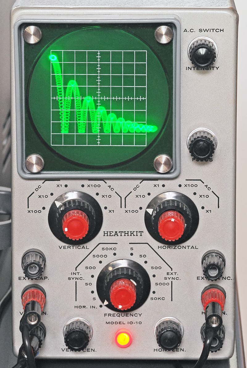
FIGURE 19. A vintage Heathkit XY oscilloscope displayed the bouncing ball.
For example, you could simulate the ball falling on the earth, the moon, or even Jupiter. Or, the ball could be made of steel, lead, or rubber. I spent much too much time playing with it. On the trace, notice how the rubber ball flattened out in the first few bounces. Pretty neat.
THE NAME GAME
Is it an ES-400 or an H-1? Heathkit didn’t assign a unique model number to this computer, causing some confusion. ES-400 actually refers only to the cabinet and front panel, not to any of the power supplies or op-amps which have their own designations. Over the years, some people have referred to it as Model H-1 which probably sounded right since Heathkit’s early digital computers had numbers like H-8 and H-11. Bottom line: Call it what you may, it’s still a cool machine.
WHO WOULD BUY AN ES-400 FOR $8,175?
Back in its heyday, the ES-400 was a good “low cost” alternative for industrial and educational laboratories, as compared to the expensive room-sized analog simulation machines found in big research labs. It was used to simulate the dynamics of automotive suspensions, water flow through cooling systems, and air flow around aircraft wings.
As digital computers and simulation programs improved, the old analog simulators were eventually outmoded and finally retired. They became just another chapter in the unstoppable march of computer technology.
WINDING DOWN
Well ... that’s about it. Again, I’d like to thank the generous person who responded to my quest and made this restoration possible. Plus, I must thank the following people for their advice and Heathkit knowledge: Bruce D, Dick H, Wayne R, Chuck P, Dave I, and anyone else I might have forgotten.
The problem with big projects like this one is finding space to store it. I don’t have a barn. So, I’ve reluctantly decided to try to find it a new home, to make room for my next challenging project. Hopefully, I’ll be able to locate a private collector or computer museum who appreciates “the Big Kahuna of Heathkits” as much as I do. If you want to learn more about the history of analog and hybrid computers, I recommend Wikipedia. I also welcome any comments or corrections about this article and encourage other owners or fans of ES-400s to contact me to swap a few stories at [email protected]. NV
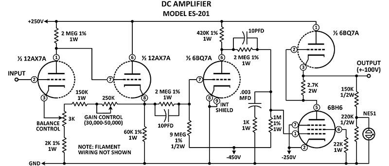
FIGURE A. The op-amps had an output swing of ±100V at 10 mA.
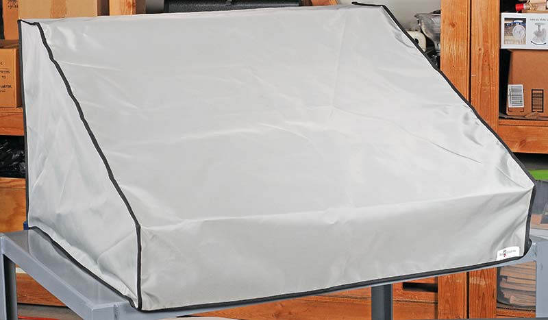
FIGURE B. A custom nylon dust cover was the final step.
PARTS LIST FOR HEATHKIT ES-400 BOUNCING BALL SIMULATION IN FIGURE 17.
| Designator |
Component |
Digi-Key (unless noted) |
| R1, R3, R4, R8, R12, R14, R21, R23-R25 |
Resistor, 1 meg, 1/2W |
1.0MH-ND |
| R2 |
Resistor, 200K, 1/2W |
200KH-ND |
| R5, R6, R10 |
Resistor, 10 meg, 1/2W |
10MH-ND |
| R7, R22 |
Resistor, 2 megs, 1/2W |
2.0MH-ND |
| R9 |
Resistor, 5 megs, 1/2W |
5.0MH-ND |
| R11 |
Resistor, 20K, 1/2W |
20KH-ND |
| R13 |
Resistor, 500K, 1/2W |
510KH-ND |
| R15, R16, R18 |
Resistor, 10K, 1/2W |
10KH-ND |
| R20 |
Resistor, 100K, 1/2W |
100KH-ND |
| R17, R19 |
Potentiometer, 25K |
*R-V38-25KL |
| C1, C2, C3, C5 |
Capacitor, 1 mfd, 630V |
*C-FS-630-1MFD |
| C4 |
Capacitor, 0.1 mfd, 50V |
399-4151-ND |
| PLUG 1-30 |
Dual Banana Turret Plugs |
501-2414-ND |
| LEAD 1-35 |
Banana Test Lead, 4” to 24” |
501-XXXX-ND |
* Antique Electronic Supply