This system plays my collection of vintage rock and roll and country music songs the way I remember how they used to sound.
When I was in high school in the early 1960s, I learned electronics with vacuum tubes. One of my favorite gadgets was the amplifier out of an old jukebox (I don’t remember the make or model). I had a huge amount of fun and learned a lot — including what 400 volts DC felt like as it traversed my right hand, wrist, and forearm.
I noticed an amplifier on eBay that was out of a 1952 Rock-ola 1436 jukebox, and just had to have it. It was essentially a dead carcass, as you can see in Photo 1.
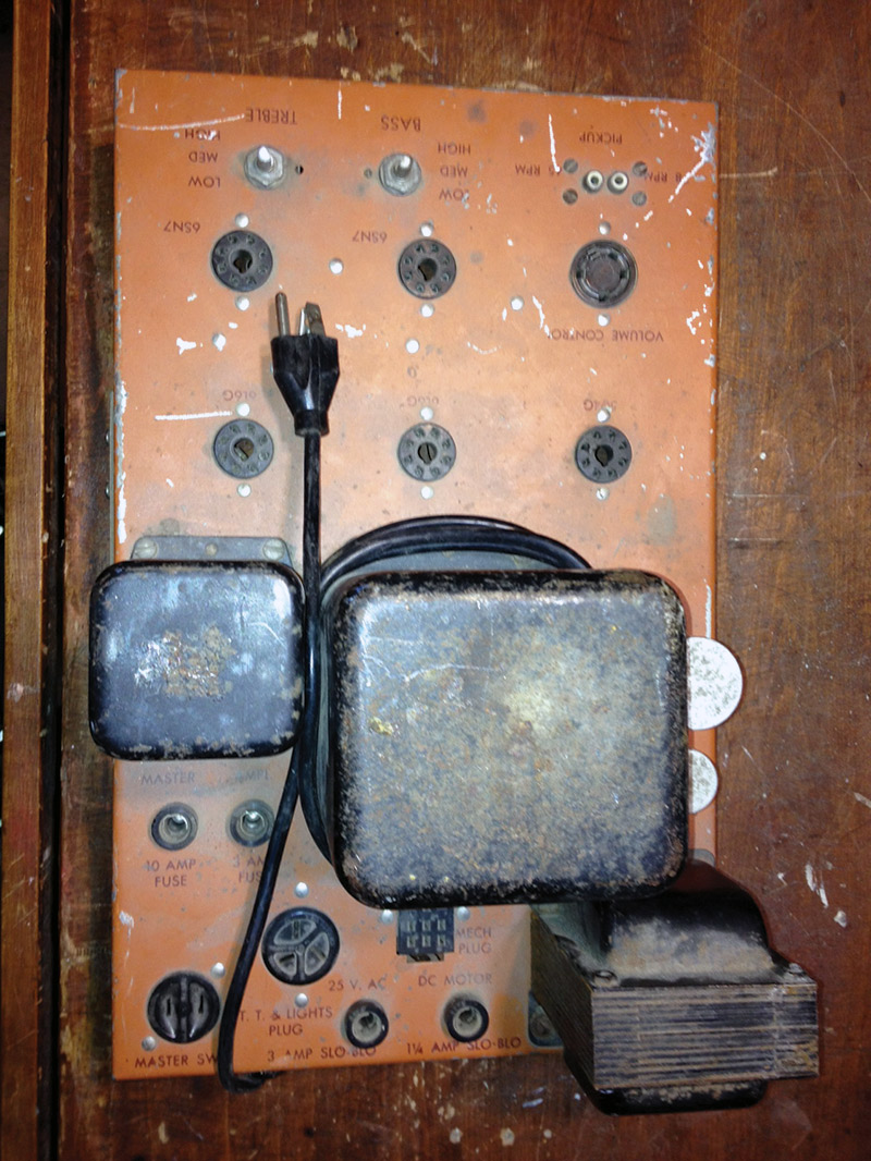
PHOTO 1. Rock-ola 1436 jukebox amplifier, as acquired.
Photo 2 shows the whole jukebox, similar to ones I remember existing in bars, cafés, and pool halls.
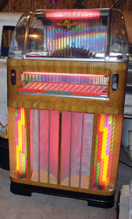
PHOTO 2. A complete Rock-ola 1436 jukebox, circa 1952/53.
Photo 3 shows a 1436 amplifier inside a jukebox with its interconnecting control cables, speaker, etc.
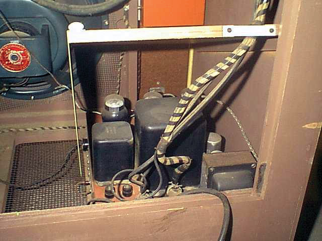
PHOTO 3. The amplifier inside the jukebox.
Purchasing an entire restored and working jukebox today is possible but was way outside my hobbyist budget, so I decided to restore the amplifier and make it able to stand alone. I wanted to make the restored amplifier as authentic as possible to the 1952 version.
I quickly determined that the transformers were still good, and decided to proceed. I acquired a complete service manual for a 1436 jukebox that came with a complete schematic (included here for reference purposes only) with all the tube pin voltages and parts list.
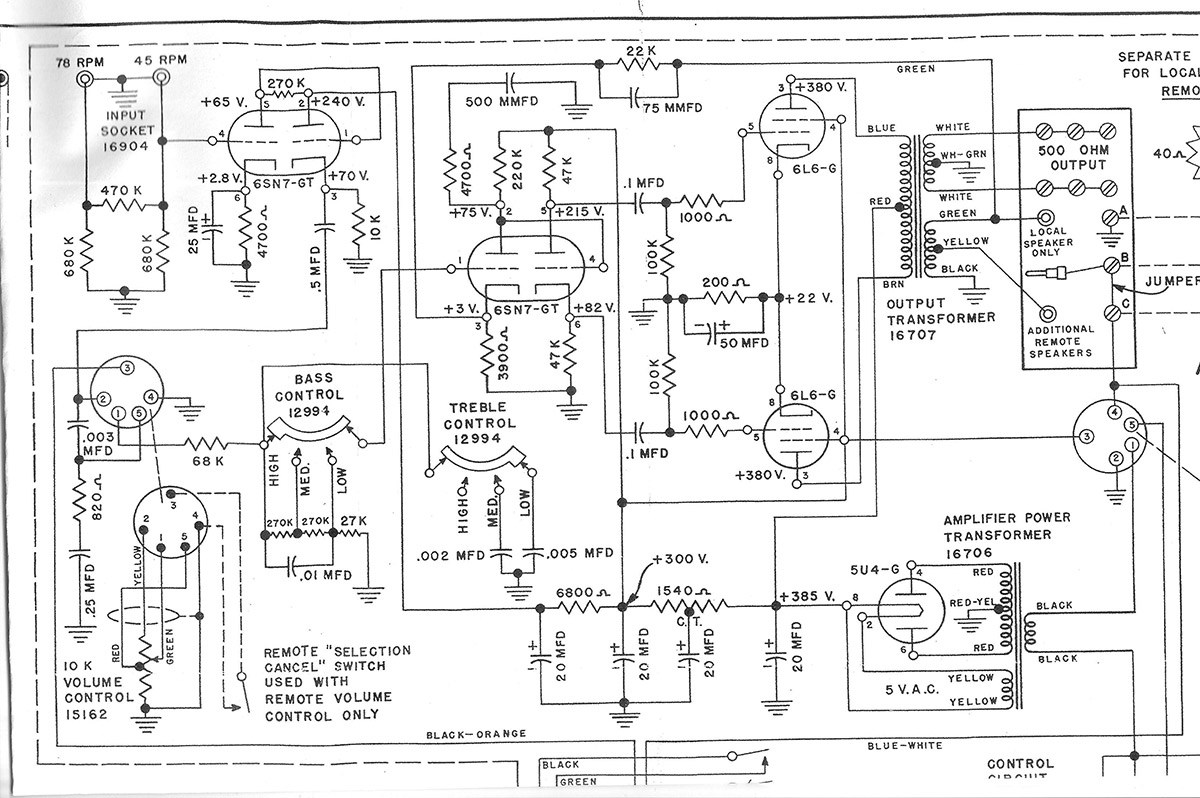
SCHEMATIC.
I decided that rather than just bringing the amplifier back to life with all of its scratches and rust, that I would strip it down to the bare metal and totally rebuild it using some of the existing electronic components, as well as any period-appropriate replacements. To help ensure that I could faithfully rebuild the internal electronics, I took several close-up photos like the one in Photo 4.
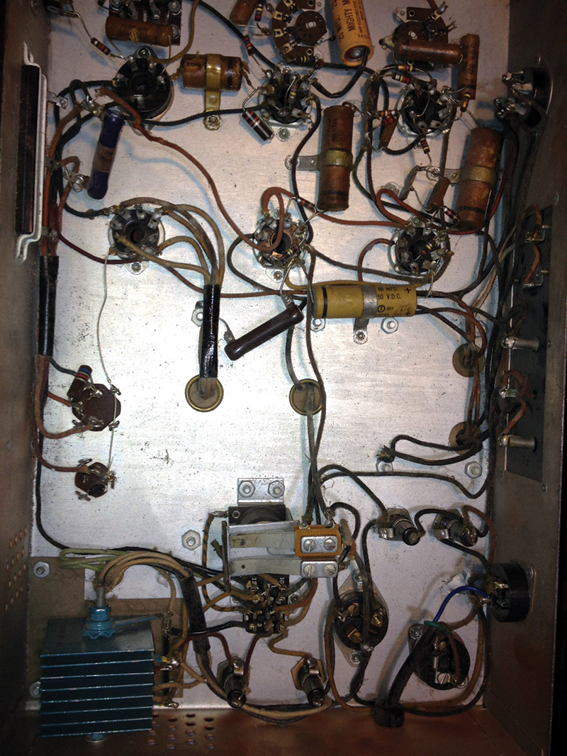
PHOTO 4. Reference shot of the underside of the 1436 chassis before restoration.
I knew from experience that after 60 years, all of the electrolytic capacitors and wax paper and foil capacitors would need to be replaced. I didn’t have too much trouble finding exact replacements for the electrolytic capacitors, but the wax paper and foil capacitors had to be replaced with somewhat more modern disk ceramic or polypropylene film capacitors.
The relay and selenium rectifier that you can see in Photo 4 were part of the control circuitry for other jukebox mechanisms. Photo 5 shows the chassis after removal of all the components.
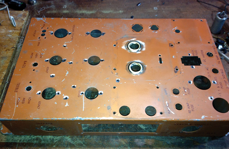
PHOTO 5. Bare chassis before refinishing.
I found it advantageous to remove most of the electronics as one mesh (seen on the right side of Photo 6).
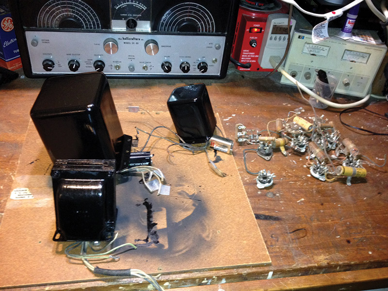
PHOTO 6. Repainted transformers and underside wiring assembly.
This greatly assisted me during the rebuild in the positioning of components and the routing of wires in order to help ensure that 60 Hz hum and other problems with the layout could be minimized. I had decided to use new (but period-specific) tube sockets and new resistors in most instances. You can see the transformers getting their facelift with fresh paint.
Photo 7 shows the finished chrome-plated chassis. I decided not to attempt to fill or otherwise disguise any unused holes in the chassis, but to fill the holes with their original connectors — even if they were unused in the rebuilt amplifier.
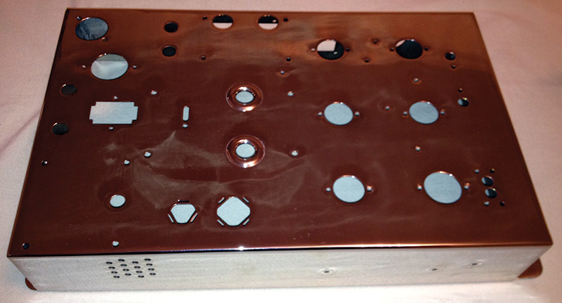
PHOTO 7. The 1436 chrome-plated chassis ready for rebuild.
There actually aren’t any dents or blemishes in the chassis. What shows in Photo 7 are reflections from other surfaces in the room where the photo was taken.
Over the span of a couple months at the rate of a few hours here and there, evenings and week-ends, I tracked down all of the parts I needed. For harder-to-find items — such as tube sockets, tubes, electrolytic and high voltage capacitors — my best source was Antique Electronic Supply (www.tubesandmore.com). The vacuum tubes are all new Russian-made varieties with the original tube numbers. It’s nearly impossible to describe the precise sequence of re-assembly and testing of all the electronics, but naturally great care was taken to position components and route wires as closely as possible to the original positions.
The first major milestone was mounting and testing all of the transformers. I was very glad that I had marked each wire on each transformer. Even though all of the wires were originally different colors, after 60 years they were all pretty much the same dull brown, not to mention a little brittle. This stage included installing the power cord, main fuse holder, and a main power switch (in one of the unused fuse holder holes).
The next major phase included routing most of the wires, such as the filament and high voltage wires. I found that while the transformer wires were a little brittle, the other original cloth-coated wire from 60 years ago was still fully usable. Nevertheless, I used new (but again, period-appropriate) cloth wrapped plastic insulated wire throughout for authenticity.
I made another significant change to the wiring layout. My original design had one leg of the 6.3 VAC filament voltage grounded, with only one wire carrying the filament voltage to each tube. This method is a known source of 60 Hz hum problems, and was not used in subsequent models of this and other early vacuum tube amplifiers. Therefore, I used tightly twisted pairs of wires to carry the filament voltage to each tube.
I chose the routes for the twisted pairs using known good techniques described in old handbooks and the routing from the original design. Newer models of this amplifier and others from the period also included a “hum balance” control consisting of the potentiometer connected between the two legs of the 6.3 VAC voltage, with the sliding tap connected to ground. It turned out to be unnecessary.
As the wiring proceeded, when any live testing was conducted I always brought up the amplifier using a variac while checking numerous voltages throughout the circuit. This was mostly necessitated by two facts.
First, the 1950’s distribution voltage was 110 VAC, while most distribution voltage today is usually 120 VAC or more. Mine consistently measures 123 VAC. The second reason is that the original jukebox used a speaker which had a large electromagnet for its field coil that drew a significant amount of high voltage current from the amplifier’s high voltage power supply. Photo 8 shows the completely rebuilt amplifier.
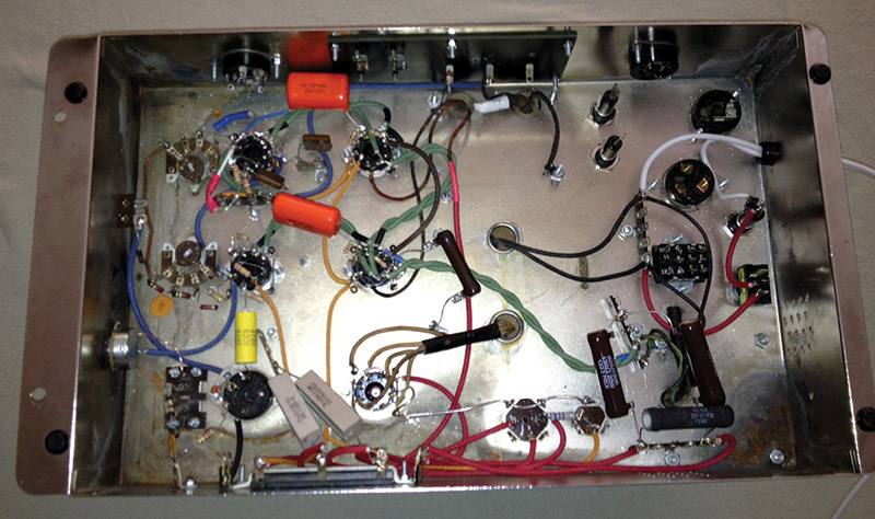
PHOTO 8. Completely rebuilt amplifier.
You can also see in the lower part of Photo 8 several large power resistors in series/parallel combinations whose values were mostly experimentally determined to compensate for the lack of current drain by a large speaker field coil and the slightly higher line voltage. You may also notice that several sockets were simply cleaned and reinstalled to avoid the presence of unsightly empty holes in the chassis.
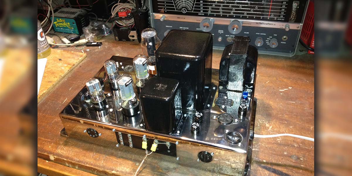
Since the original amplifier was installed deep inside of the jukebox, it had an external volume control. So, I installed a volume control in the chassis on the left. That was the only new hole that I drilled. Photos 9 and 10 show the completed project.
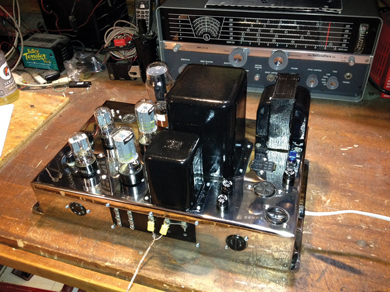
PHOTO 9. The completely restored jukebox amplifier.
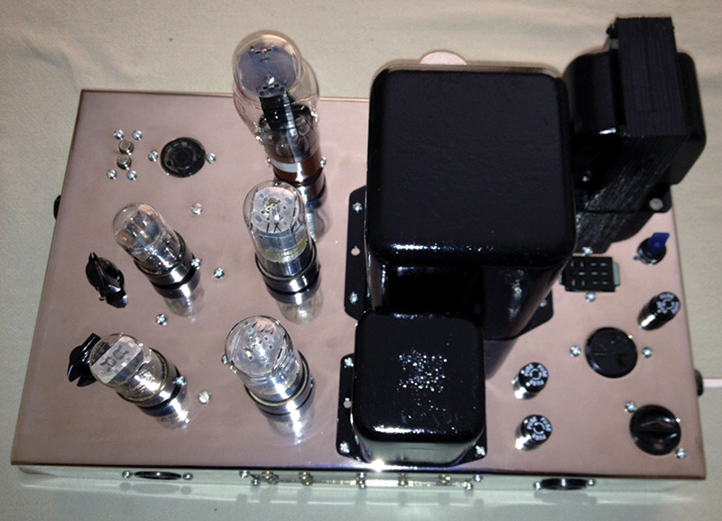
PHOTO 10.
I believe that the restored amplifier is as close to authentic 1950’s technology as can be done. The chrome-plated chassis might be a bit of overkill, but it is a thing of beauty!
I was pleasantly rewarded with practically inaudible 60 Hz hum and perfect sound (well, as good as you could get from a 1950’s jukebox). I have it connected to a vintage 15 inch, eight ohm speaker and use various audio sources such as a CD player and my iPhone. All together, the system plays my collection of vintage rock and roll and country music songs the way I remember them. Elvis sounds like he did 50 years ago.
It does a pretty good job with newer music, as well. In spite of the fact it only produces about 20 to 25 watts of audio, it can still drive you from the room. NV