How do you turn that thing?
There sure is a lot of variation in the types of antennas! All the different ways signals propagate require different antenna directions and types. Hams use dinky finger-sized “rubber ducks” on handheld radios but also some ridiculously big antennas it seems. Hams can’t use as much power as some of the other communication services, so they use antennas to get through by focusing radiated power.
If the antennas can focus a signal, then they need to be able to focus it in the desired direction, right? A few antennas can do that electrically by controlling the signal’s phase or switching antenna elements on and off. Most of the “pointable” ham antennas, though, need to be pointed mechanically and held in place during a contact or to keep a communications link working. The thing that hams use to point their antennas — large and small — is called a rotator.
There are a wide range of rotators, just like antennas. You may have used a TV antenna rotator with its “chunk-chunk-chunk” stepping. At the other end of the scale, whole towers turn! We’ll cover some of the most common types and give you an idea of how they work. (If you want detailed information, including guidelines and illustrations for how to work with these unsung heroes of the antenna farm, see the sidebar, “Rotator and Tower Know-How.”)
Rotator Sizes
TV antenna rotators are just about the smallest version used by hams. They are inexpensive and suitable for small Yagis or log-periodics for VHF through microwaves. They aren’t sturdy enough to be used with large HF beams or microwave dishes. They can’t hold antennas with a significant wind load, meaning a large surface area that generates torque on the mast or tower it’s mounted on. There are also small portable rotators that work from 12 VDC.
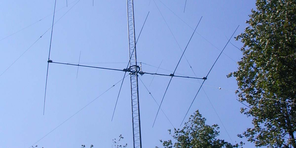
Medium-duty rotators can handle a single mid-sized HF Yagi or log-periodic for 14 to 30 MHz. By “mid-sized,” I mean a Yagi with a few elements on a 12 to 18 foot boom weighing 50 pounds or less. A small VHF/UHF Yagi can be stacked with the HF beam. This is a very common configuration: a three-element “tribander” (20, 15, and 10 meters) with a six-meter and two-meter Yagi above it. A few sections of Rohn 25 tower or an HDBX self-supporting tower (www.rohnnet.com) make for a sturdy antenna system.
Rotor or Rotator?
Is it "rotator" or "rotor?" Hams are not very precise with slang and jargon, so both words are used referring to the same thing: A device that aims an antenna in a specific direction. Nevertheless, there is a proper usage! A "rotator" is a device that causes something to rotate; in this case, a mast with an antenna attached to it. A "rotor" is a part of a device that rotates such as a motor shaft or armature.
If you want to be correct when referring to the gadget that you use to aim your antenna, call it a rotator. Thank you, I feel better now!
These rotators can also handle a set of several VHF/UHF antennas known as a “stack.” If you want them to point (and hold) a dish antenna up to a meter or so in diameter, check the dish wind load to be sure it won’t overload the rotator. A dish antenna’s main beam is very narrow — maybe just a few degrees — so a rotator has to be both accurate and stable to hold the dish in place and on target.
The biggest amateur HF Yagis — including stacks of two or three antennas — require a much larger rotator. Instead of a solenoid or disc braking system, some of these rotators use a gear train or worm drive to provide the braking action. Be sure the tower and supporting hardware is rated to handle the antenna and mast load.
As the rotators increase in capability, they also increase in size. The larger models can be hard or impractical to install in lattice type towers like a Rohn 25 or the smaller self-supporting models (refer to Figure 1).
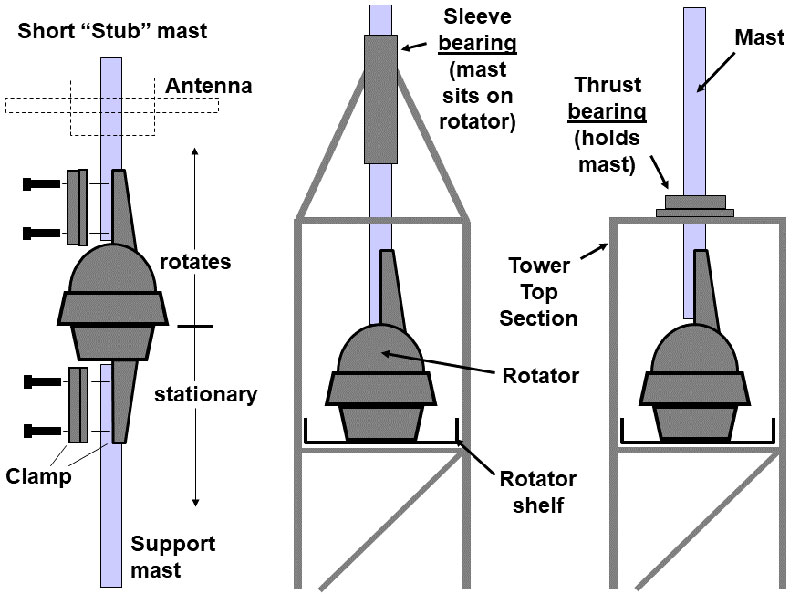
FIGURE 1. The most common methods of mounting rotators are directly on masts or inside lattice-style towers. Rotators can also be mounted directly on the top of towers (not shown). Mounting the rotator on the mast (left) exposes the rotator to bending forces, reducing its maximum wind load rating. Mount the antenna as close above the rotator as possible in this configuration.
What if you have several big antennas that you want to put on the same tower? If you need to aim independently, it’s not possible to use a regular rotator. For the lower antennas, ring rotators or orbital ring rotators are a special type of unit installed outside the tower, attached to its legs. The antenna is carried by a motorized cradle that moves around the tower on a circular toothed track that acts as a drive gear. Some hams simply rotate the entire tower with the guy wires attached to bearing rings, allowing the tower to turn inside them (see Figures 2A and 2B).
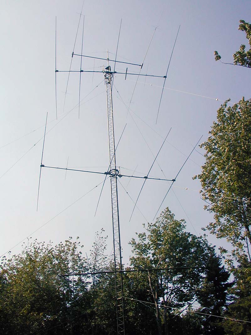
FIGURE 2A. Doug N1LI’s tower has a pair of large single-band Yagis mounted on ring rotators: one at the very top and one about half-way down the tower. This allows them to be aimed independently. The top one is aimed to the left and the bottom one to the right. A third two-element Yagi is mounted on a mast turned by a conventional rotator mounted in the tower.
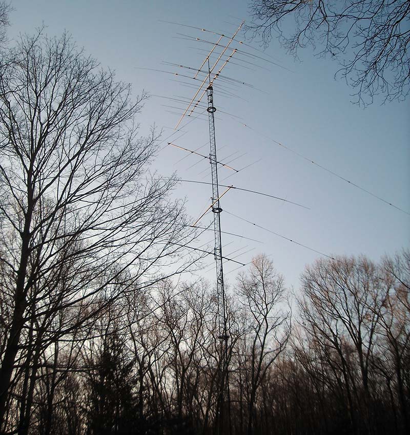
FIGURE 2B. The tower at Dave NN1N’s station is an example of a rotating tower. The rings with guy wires attached look like the ring rotators in Figure 2A, but there are no antennas attached to them. A chain-drive system at the base turns the whole tower at once.
There are also rotators that can turn antennas in the vertical plane. They are designed for satellite operating and are called azimuth-elevation or az-el rotators. This is somewhat complicated mechanically, as you might imagine. Yaesu is the largest commercial vendor of amateur az-el rotators, but the SatNOGS group (www.satnogs.org) has designed a 3D-printed system for automated telemetry reception with lightweight antennas.
Making Things Turn
Small TV antenna rotators have a stepping motor that moves in fixed increments (the chunk-chunk-chunk noise). For continuous-rotation rotators, the most common motor is a two-phase AC motor with a starting capacitor. The capacitor is switched between phases to control the direction of rotation.
Because of gear reduction, the motor can be fairly small and doesn’t draw much current. Large rotators have bigger motors, but the increase in strength is mostly due to improved gear and brake systems. The power required to turn even big arrays is not that much.
Rotators are designed to turn a full 360 degrees and sometimes a bit more. At the ends of rotation, mechanical limit switches open to remove power from the motor. This prevents feed line damage from being wrapped around the tower.
To accommodate the rotation without stretching the feed line, leave a rotator loop in your feed line that is equivalent to one full tower circumference or more. Secure it to the antenna and tower in such a way that it doesn’t get pulled or scuffed when the antenna is repeatedly turned to either extreme.
Making Things Stop Turning
Small rotators hold the antenna mast against the wind with a friction disc arrangement. When the rotator turns, the discs move apart to let the mast turn freely. When power is removed, the discs clamp together again.
Medium-sized rotator brakes consist of a heavy-duty solenoid and a spring-loaded wedge or bar that fits into indentations inside the rotating housing. Braking strength is determined by how securely the brake is held by the indentations or — if worm gears are used — by the resistance to the gears turning backward under load.
To turn the rotator, the solenoid is energized, pulling the brake out of the indentations. Energizing the solenoid is usually the largest current draw of the rotator.
When rotation is complete, the solenoid is de-energized and the brake re-engages the indentations, holding the mast in place. Over time, the indentations or wedge can wear out, allowing the rotating housing to slip under heavy loads. Wear is accelerated by de-energizing the solenoid while the mast is still turning, causing the brake to impact the sides of the indentations. If your rotator doesn’t have a brake delay, practice allowing the antennas to coast to a stop before letting the brake re-engage.
The largest rotators, including prop-pitch rotators originally used to control the angle of aircraft propeller blades, use the gearing of the motor to hold the mast in place. Worm gear drives are also designed that don’t allow backward turning under load.
Rotator Ratings
It’s important not to overload a rotator. If you live in a location that is prone to high winds, persistent winds, or large gusts, include a safety factor when selecting a rotator. Persistent twisting from winds can wear out a rotator’s brake. Rotators are not inexpensive and a failed rotator brake can allow an antenna to “freewheel,” damaging the feed line as well.
Table 1 lists manufacturers for rotators and Table 2 contains the primary specifications for common rotators.
Table 1 – Rotator Manufacturers.
| Mfr |
Model |
Wind Load (in tower, sq ft) |
Wind Load (outside tower, sq ft) |
Turning Torque (in-lb) |
Braking Ability (in-lb) |
Eff Moment (ft-lb) |
Brake Type |
Duty Rating |
| Hy-Gain |
T2X |
20 |
10 |
1000 |
9000 |
3400 |
Wedge |
Heavy |
| |
AR-40 |
3 |
1.5 |
350 |
450 |
300 |
Disc |
Light |
| |
CD-45II |
8.5 |
5 |
600 |
800 |
1200 |
Disc |
Medium |
| |
HAM-IV |
15 |
7.5 |
800 |
5000 |
2800 |
Wedge |
Medium |
| Yaesu |
G-450A |
10.8 |
5.4 |
516 |
2604 |
|
Gear reduction |
Light |
| |
G-800DXA |
21.5 |
8 |
955 |
3472 |
|
Mech and elec |
Medium |
| |
G-2800DXA |
32.3 |
10.8 |
2170 |
21700 |
|
Mech and elec |
Heavy |
| Alfa-Spid |
RAK1 |
|
|
1400 |
>14,000 |
|
Worm gear |
Heavy |
| Channel Master |
9521HD |
|
|
100 |
|
|
|
Light |
(Table courtesy of the American Radio Relay League.)
Wind Load
This is usually specified as a maximum antenna area in square feet. Antenna manufacturers specify the wind load of their antennas this way, too. For multiple antennas on a single mast, add all of their wind load specifications together. It doesn’t matter if they are all on the same side of the mast or not. A rotator’s wind load rating is often given both for the rotator mounted inside a tower and mounted on top of a mast. The rotator can handle a bigger wind load when mounted inside a tower section because the tower holds the mast in place straight above the rotator. This eliminates any sideways load on the rotating assembly relative to the base.
Braking Ability and Turning Torque
Braking ability is the maximum twisting force the rotator can withstand, primarily caused by the wind. Turning torque is the maximum amount of torque the rotator can produce to turn the antennas. Both braking ability and turning torque are given in inch-pounds.
Effective Moment and Vertical Load
The product of antenna weight and turning radius of a maximum antenna system size is used as a spec by the Hy-Gain company. Heavy and bigger antennas are harder to turn and to hold in place against the wind, requiring a higher effective moment rating for the rotator. Many rotators also specify a maximum vertical load in pounds or kilograms.
Determining Direction
For local point-to-point connections, a topo map and compass are usually enough to get your signals “on target.” For long-distance over-the-horizon contacts, though, you need to know about azimuthal-equidistant maps. Such a map (centered on your location) shows the correct bearing to any point on the globe (Figure 3).
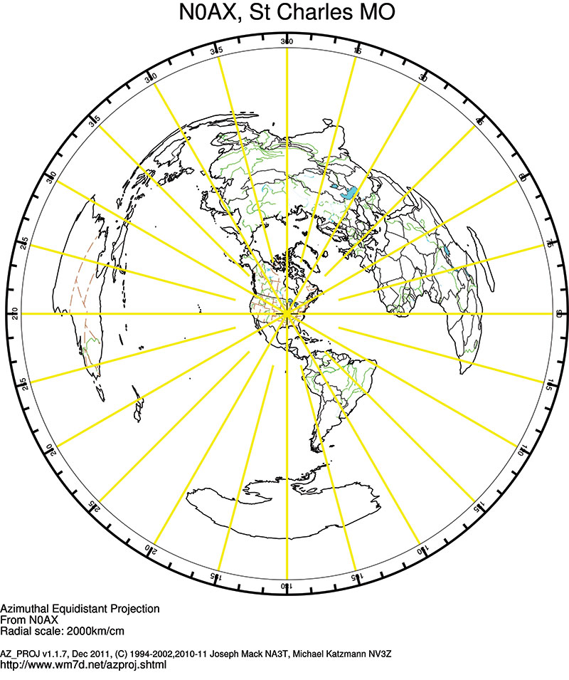
FIGURE 3. An azimuthal-equidistant map centered on the NØAX station in Missouri. While my latitude (40 N) is about the same as that of Spain, the great circle direction to Europe is between 30 and 60 degrees! Australia and Africa are almost straight west and east, respectively.
All the great circle paths from your location are straight lines heading directly to the edge of the map. This is the path your signal takes, and it may be in a direction you’re not expecting. For example, viewed on a Mercator projection map, the path from St. Louis to, say, Berlin is almost straight east. However, the path your signal would take is about 35 degrees east of north!
Most of the analog meter scales for the popular Ham-IV and Tailtwister rotators are north-centered with north at the top and south at either end of the scale. You can also special-order south-centered scales or print your own using the free program, MeterBasic (http://tonnesoftware.com/).
Controlling the Rotator
Each rotator family has their own custom control units for energizing the rotator and displaying antenna position. There are also after-market control units that operate with any of the common rotators. The most widely used are the Green Heron controllers (www.greenheronengineering.com) and the EA4TX interfaces (ea4tx.com). Both can control most available models of rotators, allowing you to standardize in the shack and customize on the tower.
It’s more common for rotator controllers to have a software interface; either RS-232 or USB. The most popular protocol is the one used by the Yaesu family of rotators. After-market software control interfaces such as the Easy-Rotor-Control (www.vibroplex.com) or Rotor-EZ (www.hamsupply.com/rotor-ez-hy-gain-rotor-control) can be installed in the rotator’s controller and connected to your PC. Many of the popular logging software programs will control a rotator as well.
Wiring Them Up
Finally, you have to supply the wiring between the controller and the rotator. There is also a wireless solution provided by Green Heron (see the URL previously mentioned), but you still have to get power to the rotator up on the mast or tower.
Most rotators require either an unshielded six- or eight-conductor multi-conductor control cable. Small TV rotators only need a four-conductor cable similar to a zip cord. Solenoid brake circuits need a heavy wire pair, but the rest of the circuits are low current. Check the manufacturer’s recommendation for minimum wire size, which depends on the length of the cable.
For the popular Ham-IV series, minimum recommended wire sizes are:
Up to 125 ft: #18 (solenoid), #20 (all others)
125 to 200 ft: #16 (solenoid), #18 (all others)
200 to 300 ft: #14 (solenoid), #16 (all others)
Other rotators have similar requirements. I’ve had good results from using long runs of 10-conductor irrigation cable, which is rated for direct burial. The conductors in the cable are #18 AWG (solid), but you can double-up two pairs of wires to create the heavy wires needed for the brake.
Wrapping Up the Rotator
Rotators are remarkably reliable, even though they are installed outside and expected to work over a wide range of conditions with no maintenance. Repair services such as The Rotor Doctor (http://rotor-doc.com/) or Norm’s Rotator Service (www.normsrotorservice.com) will rebuild them and may have used units available, too.
Often overlooked, the rotator is worth installing carefully and being treated with care. After all, your ham radio success turns on them! NV