SERVING UP SERVO CONTROL
You can't swing a soldering iron around the pages of Nuts & Volts, SERVO Magazine, or any other electronics magazine without bumping into a gaggle of advertisements and articles about servo controllers. And, why not? Servos have become ubiquitous in animatronics and robotics at the hobbyist level and all the way up to the pros. I don't know who created the first servo controller, but I'm pretty sure that Scott Edwards and his products popularized the concept with his mini SSCs (serial servo controller) — especially way back in the days when the BASIC Stamp was about the only friendly controller in town.
In concept, a servo controller is a slave processor that manages connected servos by providing regular position updates (more on this below), relieving the host processor of that burden. Most servo controllers use a serial connection to receive commands from the host. The host sends a short message to the servo controller detailing which servo to move and to where. Advanced features include setting the rate at which the servo moves between point A and point B, and even the ability to specify a move time where the rate of movement is determined by the size of the move and the desired timing.
With 28 available pins (I tend not to count the programming/debug and EEPROM pins), Propeller projects often have plenty of I/O, and having eight cogs (processors) at our disposal means there's usually brainpower to spare, too. Of course, the Propeller can use a standard serial servo controller, but if we have the pins we might as well trade a serial cog for a custom servo control cog. What about when we need a special feature? No problem! It's just a small matter of programming.
Servo Control Basics
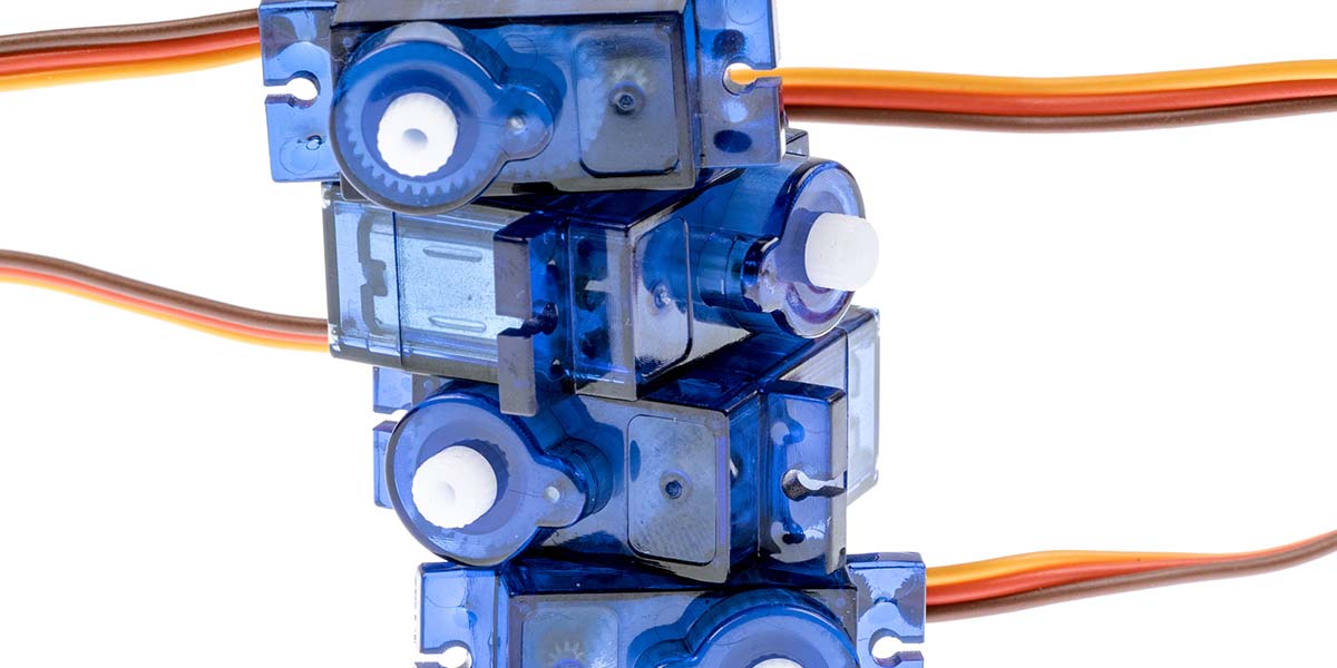
For the two of you that didn't skip over this section, I want to clarify that the kind of servo I'm referring to is the small, specialized gear-motor that many know from RC aircraft and cars; a typical servo is shown in Figure 1.
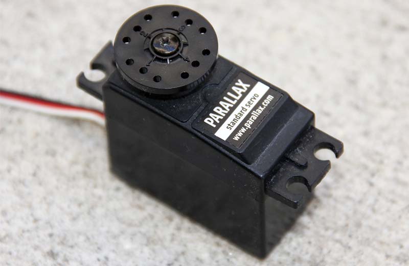
Figure 1.
Inside the servo is a small motor, a gear-train to the output shaft, and connected to that is a potentiometer and feedback circuit that allow the output shaft to be moved to an angular position defined by an input pulse from the servo controller. Figure 2 shows the position of the output shaft relative to the input position pulse width (which is expressed in microseconds).
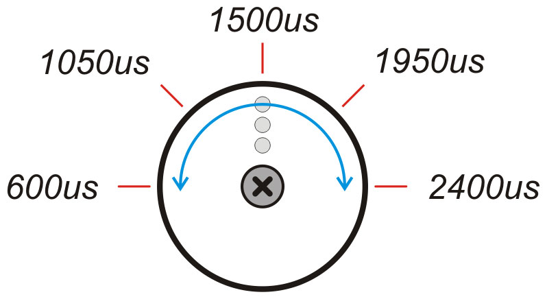
Figure 2.
The servo is connected to its host with a three-pin female connector (Figure 3) that mates with a male header (square post header on 0.1" centers) on the servo controller. The white (or yellow) wire carries the control signal; the red is the supply voltage (typically 4.8 to 7.2 volts); and black is ground. If a project separates the controller supply from the servo supply, the grounds must be connected.

Figure 3.
To move the servo to a desired position, a command pulse of the required width is placed on the signal line by the servo controller; this position pulse is typically refreshed every 20 milliseconds (50 times per second) as shown in Figure 4.
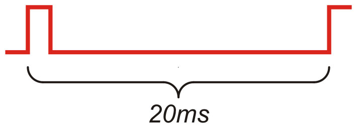
Figure 4.
That last part tends to catch BASIC Stamp users by surprise, and can complicate simple BASIC programs; I believe this is what lead to the birth and popularity of the serial servo controller.
Propeller Powered Servo Control
Most applications — particularly in robotics — will, in fact, require the ability to control more than a single servo. A trick that my friend John Barrowman (not the English actor) taught me is to "walk" the servo outputs. This trick simplifies the software in that only one timer is required, versus one timer for each simultaneous output. Another benefit is that the small delay between command pulses gives the power supply a bit of a reprieve from the current surge when a servo starts moving. It's easier for the supply to deal with one servo surge load versus many.
Figure 5 is a visual representation of the signals from a four-channel servo controller that walks the outputs.
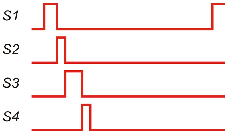
Figure 5.
Note that when the pulse from channel 1 is finished, the pulse from channel 2 can start. This process works its way through all the channels within the servo frame timing of 20 milliseconds.
Now that we know the process, let's have a look at how to tackle it using the unique capabilities of the Propeller. To start, the virtual controller is going to run inside a synchronized loop. You may remember from my last column that a synchronized loop looks like this:
sync := cnt
repeat
' code
waitcnt(sync += constant(20 * MS_001))
For review, just before entering the repeat loop, we capture the current value of the system counter. At the end of the loop, we execute a waitcnt instruction that updates the value in sync such that the loop will restart 20 milliseconds after it started — regardless of what the code between those two points is doing. The only caveat is that the loop code must consume less that 20 ms; if the loop code is too long, we'll miss the waitcnt target and will have to wait for cnt to wrap back around it (about 58 seconds later!).
As with the motor controller we did in a previous column, we're not going to generate the output pulse through direct pin manipulation. We will employ one of the cog's counters to do the heavy lifting for us. By setting the counter to PWM/NCO mode, we can move the pulse width into the counter’s phase accumulator and the rest takes care of itself.
Assuming a global array to hold the servo position values (which are expressed in microseconds), we can construct a simple walking servo controller like this:
pri servo8(count, base) | frame, idx
count := 1 #> count <# 8
outa := 0
dira := ($FFFF_FFFF >> (32 - count)) << base
frqa := 1
phsa := 0
frame := cnt
repeat
repeat idx from 0 to (count-1)
ctra := (100 << 26 ) | (base + idx)
phsa := -(pos[idx] * US_001)
waitpne(|< idx, |< idx, 0)
waitpeq(|< idx, |< idx, 0)
ctra := 0
waitcnt(frame += constant(20 * MS_001))
Yes, that's it. This method — which is designed to be run it its own cog — will generate position pulses for up to eight servos with one microsecond position resolution, and nary a line of Assembly code required! Pretty cool, huh?
Starting at the top, the code forces the value in count (the number of servos we want to control) into the legal range. The maximum value of eight is not arbitrary; with a possible pulse width of 2,400 microseconds (2.4 ms), eight servos is the most we can squeeze into the 20 ms servo frame.
The next step is to configure the output pins. This is required because the method will run in its own cog and each cog has its own pin direction register. We do need to ensure that no other cog is making any of the target servo pins high.
All cog’s outputs are OR'd together so any cog can make any I/O pin go high, regardless of the state of other cogs. In order to prevent interference with non-servo cogs, the output mask is created for the number of servo pins in count; these outputs must be contiguous.
The mask for the servo pins is created by shifting $FFFF_FFFF (all bits set to 1) right by 32, minus the number of servo channels. What we're left with is a value with "count" 1s in it. This value is then shifted left to align the LSB with the specified base pin (the first channel of our servo controller) and then is written to the dira register.
The frequency and phase registers for the counter are preset to allow precise timing and prevent a start-up glitch; then we drop into the control loop. A loop within the loop iterates through the number of servo channels, setting the counter PWM/NCO mode and then using the current channel pin. The pulse is, in fact, generated by setting the phase register to the negative value of the pulse width (this value is expressed in cnt ticks). At this point, the pulse is underway and we don't have to do anything else. That is, it will end on its own (when the value in the phase accumulator reaches zero).
The next two lines monitor the pin; first to go high (start of the pulse), then to go low (end of the pulse). When the pulse is finished, the counter is reset and the next channel pulse is generated. When all channels are complete, the final waitcnt (in the outer loop) finishes the servo frame timing.
Yes, it really is that simple. By using the counter to generate the servo pulses instead of sitting on a waitcnt instruction, we're left with a lot of useful time between servo channels. We can use this time to modify the servo position value for advanced control techniques.
Before we get to that, though, have a look at Figure 6; this illustrates a modified walking strategy that places each servo channel (again, up to eight) in its own slot.
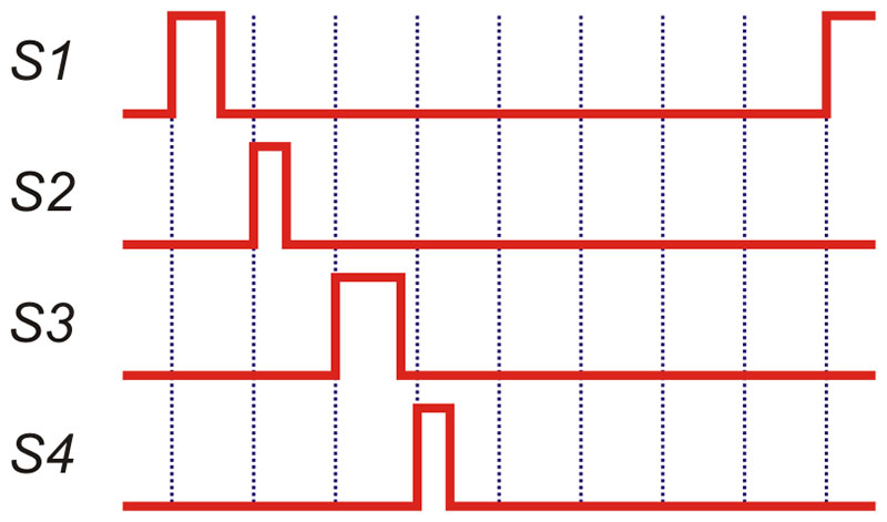
Figure 6.
The reason for this comes from my friend Peter, a Hollywood visual effects expert who has forgotten more about motion control than I'll ever know (see his servo controlled characters at www.socalhalloween.com).
While discussing servo programming over lunch, he expressed concern that the simple walking algorithm allows for a wobble in frame timing for servo channels 2 through 8. The reason for this is that the leading edge of a servo follows the falling edge of the previous, and the timing of the previous servo pulse can change. Channel 1 is not affected as it always starts at the beginning of the 20 ms servo frame.
My adjustment is simple: Divide the 20 ms frame into eight, 2,500 µS slots. A servo pulse is generated at the start of a slot; hence, leading-edge-to-leading-edge timing for every slot is always 20 ms — no wobble. Another benefit is that we now have almost 2.5 ms to manipulate the position value for a servo channel before the next slot starts. This is an eternity — even for a high level language like Spin.
Let's have a look at the modification which runs each servo channel in its own slot:
slot := cnt
repeat
repeat idx from 0 to 7
if (idx < count)
ctra := (100 << 26 ) | (base + idx)
phsa := -(pos[idx] * US_001)
waitcnt(slot += constant(2_500 * US_001))
ctra := 0
As you can see, overall timing is now controlled by the inner loop which runs eight times. If the inner loop index is less than the servo count, a pulse for the channel is generated. The slot timing is executed as usual with waitcnt, even if there is no pulse generated for that slot (i.e., when we're controlling fewer than eight channels) to maintain the 20 ms servo frame.
Since we've got almost 2.5 ms to work with during a slot, let's put that time to work. A popular feature with modern servo controllers is setting the servo speed for movement to the desired position. To facilitate this feature, we'll need two additional values per channel: 1) the new target position; and 2) the number of microseconds to change during each servo frame:
slot := cnt
repeat
repeat idx from 0 to 7
if (idx < count)
ctra := (100 << 26 ) | (base + idx)
phsa := -(pos[idx] * US_001)
if (pos[idx] < target[idx])
pos[idx] := {
} (pos[idx] + delta[idx]) <# target[idx]
elseif (pos[idx] > target[idx])
pos[idx] := {
} (pos[idx] - delta[idx]) #> target[idx]
waitcnt(slot += (2_500 * US_001))
ctra := 0
Allowing for speed control is very straightforward. After the pulse has started, we check to see if the current position (in pos) differs from the intended destination (in target). If these values differ, the position is adjusted by the channel change value (in delta) toward the destination. The max (<#) and min (#>) operators prevent over- or under-shoot of the destination position.
I'll be the first to admit that I "liberate" good ideas from wherever I find them, so when I saw the speed feature in a popular servo controller, I duplicated it. It works by allowing us to express the servo speed in microseconds (position change) per second. With 50 updates per second, the set_pos() method call that sets the new target and delta values is as follows:
pub set_pos(ch, newpos, speed)
if (ch => 0) and (ch =< 7)
newpos := SVO_MIN #> newpos <# SVO_MAX
target[ch] := newpos
if (speed =< 0)
delta[ch] := 0
pos[ch] := newpos
else
delta[ch] := (speed / 50) #> 1
This method sets the target position to newpos (which has be validated) and then looks for a speed setting of greater than zero. If we want the servo to move to target at its normal rate, we set speed to zero; doing this sets the current position value to newpos.
Non-zero speed values are divided by 50 (frames per second) and moved into delta. This is the value that we use to update the current servo position while moving to the destination.
Assuming a 180 degree servo and the lowest speed setting (1 to 50), the servo will move from one extreme to another in about 36 seconds. To make the servo move any slower would require modifications to the code that I don't think add benefit, but if you think I'm wrong please update the code and send it my way.
With speed control of the servo, we can add another method that allows us to command a servo to move from its present position to a new position in a specific amount of time (which will be specified in milliseconds). Have a look at the move_to() method:
pub move_to(ch, newpos, ms) | frames, move
if (ch => 0) and (ch =< 7)
newpos := smin #> newpos <# smax
frames := ms / 20
move := ||(newpos - pos[ch]) * 10 / frames
move := ((move + 5) / 10) #> 1
if (frames < 2)
pos[ch] := newpos
target[ch] := newpos
else
target[ch] := newpos
delta[ch] := move
This method works by calculating the number of servo frames required for the timing specified in the ms (milliseconds) parameter. It also calculates the frame-to-frame move (delta) that accommodates the timing for this distance traveled. If more than one frame is required by the move, the target and delta values are updated. Otherwise, the move is immediate.
Before we finish, let me just suggest that it's not a good idea to connect a microcontroller I/O pin directly to the signal line to the servo. The servo contains a motor and active electronics that can generate noise on this line. Many will simply put a resistor in series with the signal line; I tend to use a small RC circuit suggested by John. He was doing some work with noisy servos and found that an RC circuit using 100 ohms and 0.01 µF cleaned up the noise without degrading the signal pulse.
You can leave out the cap if you want, but don't leave out the resistor. Figure 7 shows the connections between the I/O pin and the three-pin servo header.
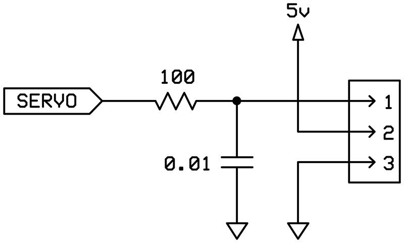
Figure 7.
Download the project code (which bundles everything discussed here into a reusable object) and have a look at the rest. You'll see that I've also added methods to set the position and move the speed of all the servos with a single call. Another method allows us to wait until a specific servo channel reaches its intended target.
For me, anyway, this is just a start. Having the ability to create servo pulses with 1 µS resolution and enough time between servo pulses to add speed control features using high level code (Spin) means that the Propeller is a very serious player in the servo control arena — especially for those projects that have available I/O. For those of you that don't want to roll your own hardware but would like a custom servo controller, you can always get a Propeller PSC from Parallax and reprogram it.
With the code we've developed here, you're well on your way. Here's a hint for controlling the other eight outputs on the PPSC: Each cog has two counters. Use the second counter to generate pulses for the second set of eight outputs. This keeps the servo pulse generation in a single cog.
Until next time, keep spinning and winning with the Propeller! NV
| Item |
Description |
| Rx |
100 ohms |
| Cx |
0.01 µF |
| Xx |
0.1 male |