One of the neatest gadgets made possible by modern IC technology is the magnetometer. For less than $25, you can construct a fun and durable tool to measure magnetic fields (static or varying) produced by currents, permanent magnets, pieces of iron, or the Earth itself. If you are or were ever fascinated by magnets, this is the instrument for you!
You may have a smartphone with an internal compass that you could use as a magnetic field sensor (assuming you know which end of the phone contains the sensor and what its internal orientation is), but these devices — while sensitive — will usually be overloaded at field strengths much above Earth's. These fields vary with position, but are generally around 0.5 Gauss or 50 microTesla. If you'd like to measure the strength of even a small magnet, the phone may not be helpful.
Allegro Microsystems (www.allegromicro.com) produces a wide variety of Hall effect sensors that can be used to detect magnetic fields. If you remember introductory physics, you may only recall that the Hall effect is the definitive way to determine whether a current is caused by the flow of positive charges in one direction or negative charges in the other (as it turns out, if you're working with a solid, it's negative charges). These devices can be purchased in three-pin Single Inline Packages (SIPs) that look very much like TO-92 transistors. For this project, these are much easier to work with than the three-pin SOT23-W form factor.
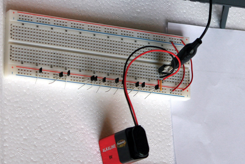
FIGURE 1. For our magnetometer, we will glue two of these chips back-to-back, and rather than measuring their outputs relative to ground, we will measure the potential difference between the two outputs. Since they are oppositely oriented, this means that an approaching south pole will cause the nearer chip's signal to rise above 2.5V, while the rear-facing chip's signal will drop below 2.5V. Measuring the difference between the two gives us two advantages. First, we double the sensitivity of the arrangement as compared to a single chip. Second — and more importantly — our baseline no-field signal will now be at or near zero volts, rather than at or near 2.5V, meaning we can use a more sensitive range on the voltmeter. If you buy several of these chips, you can match two by powering them all at once on a breadboard and looking for two with the same output.
There are multiple varieties of these Hall chips on the market. What you will need is generally referred to as a linear Hall effect sensor. This is in contrast to a binary device known as a latching chip which will be turned on by a field exceeding some strength, and not turned off until an oppositely-directed field of some strength is applied to it. I'm using an A1321 which may be hard to find now, but you can substitute an A1301, A1302, A1324-1326, or any other linear Hall chip (though I have had more success with Allegro than with some other manufacturers).
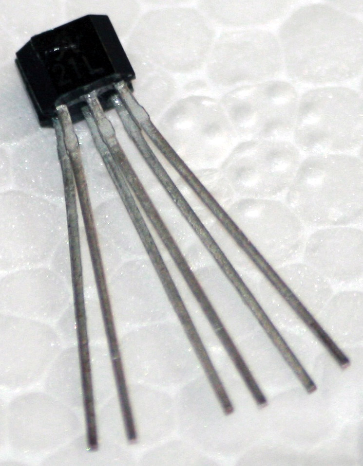
FIGURE 2. Since they all have the same orientation, are all powered by the same source, and are very close to one another, they should ideally all read the same. In reality, there are slight chip-to-chip differences. You can just move down the row of chips, recording their actual output voltages and then pick the two that are closest to equal. Once you've found two that match, you glue them back-to-back and get the package shown. (As a side note, you could, in fact, glue them face-to-back so they are facing the same way. If you do this, the difference in signal outputs will now represent the gradient of the magnetic field. Instead of telling you how strong the field is, it will tell you how much it changes over that tiny distance of a millimeter or two. If you decide to build one of these, you might want to put a spacer between the two chips so they are a centimeter or so apart.)
These chips have about the simplest design possible; when reading the numbers on the chip, the left leg is incoming power (+5V), the middle leg is ground, and the right leg is an analog voltage that ranges from zero to the powering voltage. When there is no significant external field present and the chip is powered by a 5V supply, the output will be 2.5V. For the A1321, moving a north pole towards the face will decrease this value and moving a south pole towards it will increase it. The sensitivity of the A1321 is quoted as 5 mV per Gauss.
The now six-legged package can be conveniently mated to larger connectors that are easier to work with using a regular telephone cord. You don't need a six-wire cord for this, though; the more common four-wire is sufficient. First, cut one of the modular plug ends off of the cord and strip it so that you have a plug on one end and four free wires at the other.
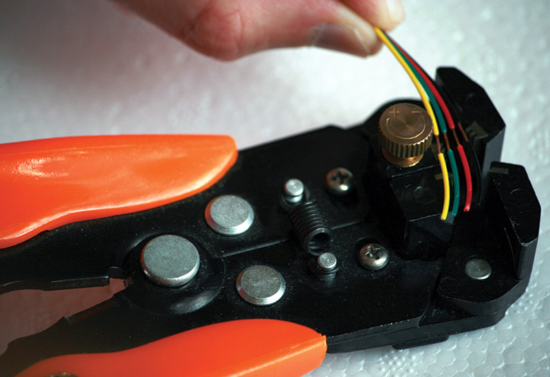
FIGURE 3. In my experience, a self-adjusting wire stripper is the perfect tool for phone lines.
Now would be a good time to check the continuity between the exposed phone wires and the terminals on the phone jack itself. It might seem obvious that the red wire will be connected to the red terminal, but all four-line phone cords are not created equal. In some of them, you'll find that red and green (for example) are swapped and that will, of course, change how you ultimately wire things up.
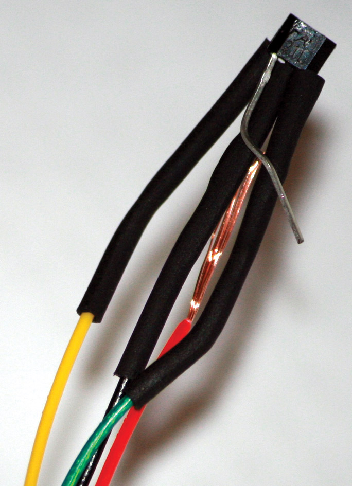
FIGURE 4A.
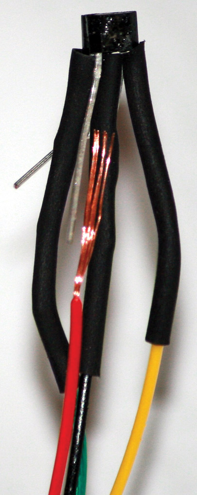
FIGURE 4B.
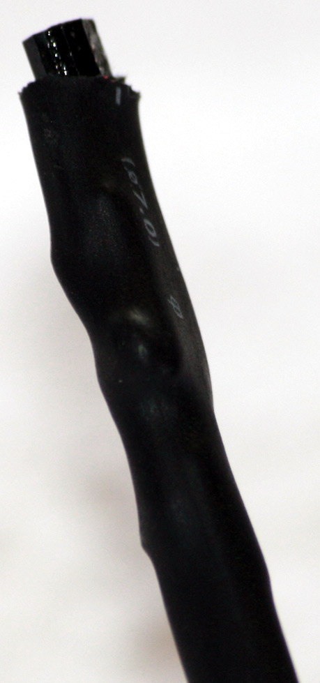
FIGURE 5. The connection process is probably what you would expect: solder and heat shrink. The fact that it has to be done in a particular order may not be expected. First, connect one of the phone wires (I used the black one) to the two ground pins which are located on top of each other since both are in the center. Make sure that, after soldering, you slide the heat shrink all the way up the Hall chips. Next, connect each of the signal legs (remember that the signal leg from each chip is the one on the right as you are looking at the numbered face) to its own phone wire (I used green and yellow for this). Here, order is not important — just solder them and again apply heat shrink all the way up. The reason for starting with ground, then signals, then power is apparent now. The two power legs are on opposite ends of this six-legged package. You'll have to sort-of bend one around the entire package to reach the other, and then connect the pair to your last remaining phone line (red, in my case). You can't use the ordinary small heat shrink for this because it will bring the two opposite legs together so tightly that they will break off. Fortunately, everything else is already covered, so this doesn't have to be. You can use one large piece of heat shrink that covers the entire probe, as shown in Figure 5.
Once the Hall chip is successfully connected to the phone wire and the heat shrink is in place, it's time to start working on the other end. Basically, you need a five volt power supply, since a nine volt battery is enough to kill the Hall chips. You can use a simple three-terminal 7805 voltage regulator in the TO-220 package. It's easy to work with and already has a hole to allow you to attach it to the faceplate holding the phone jack. When looking at the numbered face of the 7805, the input voltage (nine volts) is connected to the leftmost pin, the middle pin is connected to ground, and the right pin is the five volt output that will go to the proper colored phone terminal block (red, in my case).

FIGURE 6. We need to drill some holes in the faceplate now. You'll use two small nuts and bolts to secure the 7805 and the battery holder to the faceplate, so they need holes. You also need four holes to hold the faceplate to the electrical junction box. You'll need one more for the power LED, and if you bought a phone-only jack as opposed to the combination phone/cable jack shown here, you will have to drill a large hole to allow the alligator wires to pass from inside to outside. Simply unscrewing the cable connector provides a ready-made hole in this combination jack.
You need some kind of power switch to turn it on and off; an ordinary light switch is hard to beat for something low cost and easy to work with. The positive side of the battery clip goes into one of the switch's terminals and the other terminal is connected to the left side of the 7805. Finally, we can add an LED to make on and off more obvious.
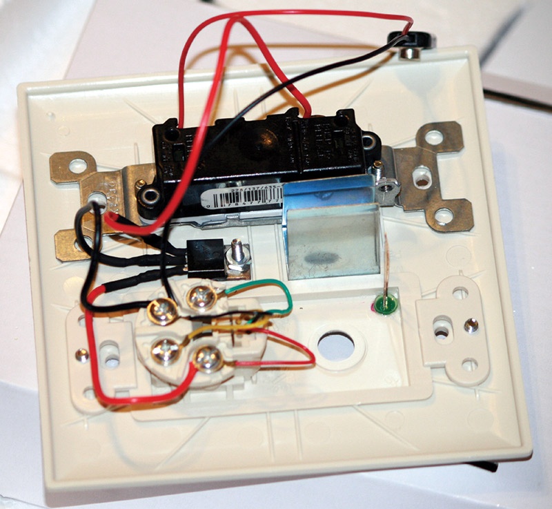
FIGURE 7. When you have made your holes, you can super-glue the LED in place and attach the battery holder. You can screw the 7805 down for the soldering process, but it might be a good idea to unscrew it and have it lifted away from the faceplate when you are using the heat gun to collapse the heat shrink tubing over your solder joints. The superheated air from the heat gun will deform the faceplate quickly if you aren't careful.
The LED should be connected to a resistor of somewhere between a few hundred and a thousand ohms. The smaller the resistor, the brighter the LED. It doesn't matter whether you connect the resistor to the positive or negative leg of the LED. Assuming you choose the positive leg, you then need to connect the free end of the resistor to either the light switch terminal (NOT the same one that the battery is connected to or you'll never turn the LED off!) or the five volt phone terminal. The negative end of the LED needs to be connected to ground.
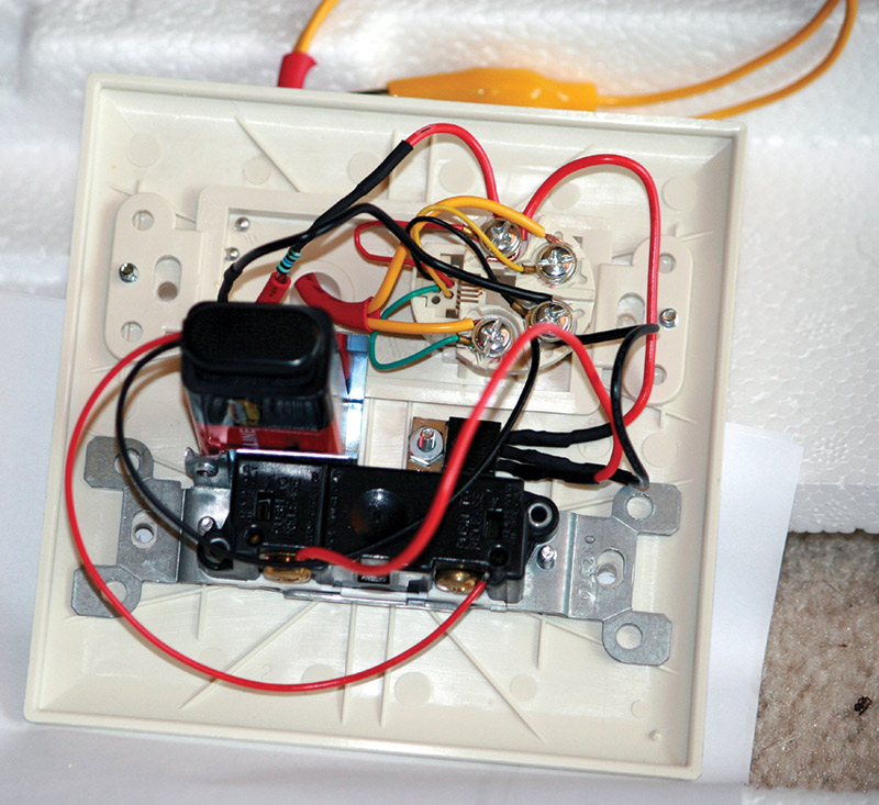
FIGURE 8. To recap, your connections on the phone terminal block are as follows: On the red terminal, we have the 7805 output and the positive side of the LED-resistor pair. On the black terminal, we have the 7805 ground, the black wire from the nine volt battery clip, and the ground side of the LED-resistor pair. On the other two terminals (green and yellow), all you need to connect are two alligator clip wires. These will ultimately be clamped to the probes of your voltmeter. You should probably bunch the two together using a long piece of heat shrink that spans the hole in the box. That will give you a little strain relief on the cable and make it less likely that the alligator cables will pull loose during normal use.
A few other things to be aware of include:
- The heat gun should not be held close to the phone jack, light switch, face plate, etc., for long periods of time or it will warp them.
- The legs can break off of the dual Hall chip if you aren't careful — they aren't made for repeated bending back and forth at large angles and will break reasonably soon.
- You might find it useful when testing your work to cut another test lead cable in half and use one of the halves to bring the ground connection outside of the electrical box. Finally, it sounds hard to believe, but one glitch has come up repeatedly over the years that I have helped dozens of students build these: The phone wire will look like it's properly plugged in, but you have to push it in until it clicks to be sure.
Once you've built the magnetometer, you can use it to measure a variety of things. You'll find that ferrous materials that you haven't magnetized will still provide a signal when held near the probe. It's certainly not a very precise compass, but you will probably be able to find the general direction of magnetic North.
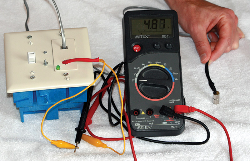
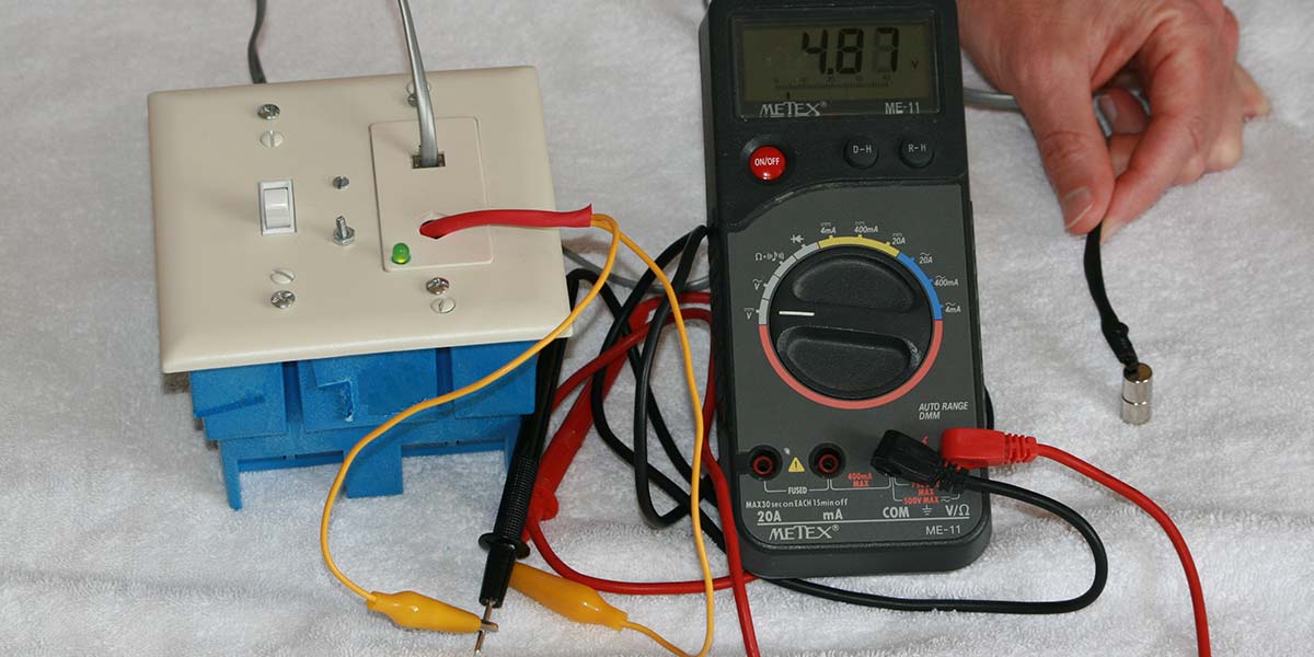
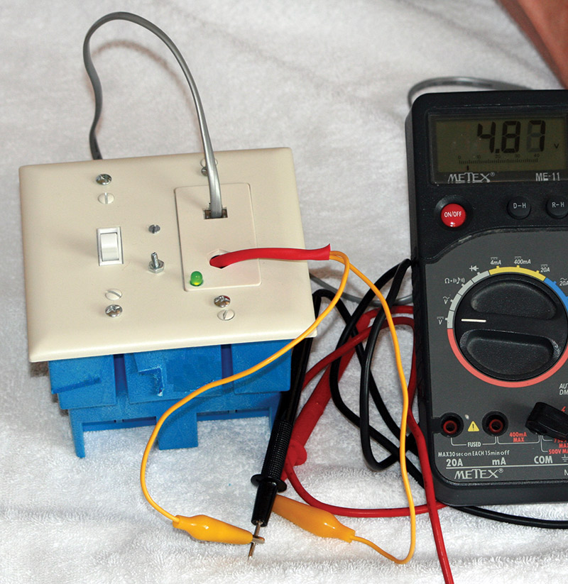
FIGURE 9. The finished product. Note that the two small Neodymium-Iron-Boron (NdFeB) magnets shown are enough to drive the chips to their limit of approximately five volts. If you flip them over, you will get approximately negative five volts.
This only requires a cheap LM358 op-amp and half a dozen resistors. The two green wires on the left side of the diagram are to be connected to a voltmeter. The two white wires on the right side are to be connected to your magnetometer outputs. For some cases, the gain will be too large. You can reduce the size of the larger resistors (shown as 100K here) and/or increase the size of the smaller ones (1K here). This can be powered by a separate 9V battery. No voltage regulator is necessary in this case.
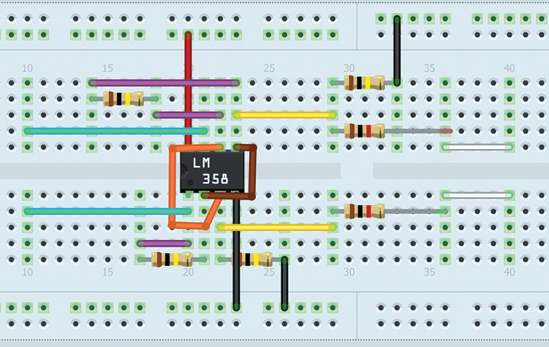
FIGURE 10. If you would like to amplify your signals, you can use this diagram.
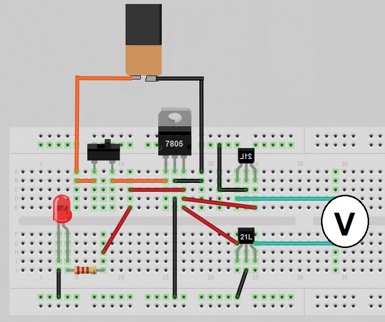
FIGURE 11. Schematic of magnetometer if constructed on a breadboard.
If your voltmeter is set for AC, you can pick up the magnetic fields produced by electrical appliances. The key here is to split an extension cord so that the two wires are not side by side. If they are, the opposing currents will produce magnetic fields that tend to cancel each other and it will be hard to detect anything.
Once you've built this magnetometer, you may be surprised at the uses for it. Anything that produces a magnetic field is a fair target, and the Hall chips respond to changing fields far faster than mechanical detectors such as reed switches. This means they can also be used as rotation sensors when placed near the edge of a gear. The field when a tooth is directly under the Hall chip will differ from the field when a gap between teeth is directly under it. In this way, you can produce a signal that corresponds to the rotation of a wheel.
You might find that a surprising number of your sensor projects can be completed with some magnets and this detector. If you build one and come up with a neat application for it, be sure to let me know! NV
Parts List
| DESCRIPTION |
PART # |
SUPPLIER |
QTY |
| Electrical Two-Gang Box |
70974 |
Lowes.com |
1 |
| Single Pole Light Switch |
83080 |
Lowes.com |
1 |
| Cable/Telephone Combo Jack |
169763 |
Lowes.com |
1 |
| Combo Nylon Wall Plate |
89198 |
Lowes.com |
1 |
| Package 4-40 x 1/2" Machine Screws |
491275 |
Lowes.com |
1 |
| 7' Phone Line Cord |
303008 |
Lowes.com |
1 |
| Heat Shrink Tubing Assortment |
16481 HS |
Mpja.com |
1 |
| Alligator Clip Test Leads |
16435 TE |
Mpja.com |
1 |
| Green 5 mm LED |
15110 OP |
Mpja.com |
1 |
| Allegro 1325 LUA Hall chips |
89T7955 |
Newark.com |
2 |
| 9V Battery Clip |
94F1482 |
Newark.com |
1 |
| 9V Battery Snap Connector |
31M0724 |
Newark.com |
1 |
| 7805 Voltage Regulator |
69R5614 |
Newark.com |
1 |
| 1,000 W resistor |
60R3433 |
Newark.com |
1 |