The August issue of N&V featured my construction article “Build a Low Cost, High Performance 12 Watt Amplifier for Eight Ohm Speakers.”
The two amplifiers are quite similar, using a very conventional three-stage design called the Lin Architecture named after Hung C. "Jimmy" Lin — an electrical engineer who invented components that are commonly used in solid-state amplifiers, audio speakers, microphones, and headphones. There will be an additional article that describes the theory behind the headset amplifier, but most of that discussion will apply to the power amplifier presented previously, as well.
This project is a headset amplifier that can be driven by a CD or MP3 player, and can drive a good high fidelity headset. My headset has an impedance of about 32 ohms; some range as high as 600 ohms. This circuit will drive any headset in that range and beyond. Some high-end audio folks consider integrated circuit operational amplifiers not to be very good ... something about too many transistors in the signal path. This circuit uses all discrete components — no more and no less than required to provide wide bandwidth and low distortion. I suppose someone will argue that $2 worth of transistors can’t possibly sound as good as a $10 operational amplifier.
I am a retired graduate electrical engineer who has been interested in audio since high school.
A few years ago, I got interested in solid-state amplifiers and bought some books on the subject. Since then, I’ve built a number of amplifiers with superior specifications and very low cost.
This simple amplifier has very low distortion and flat frequency response well beyond the audio frequency range. Cost of parts for one channel including the power supply will be about $30; a second channel will only add about another $15.
If you live in a large metropolitan area, you can find all the parts at a local distributor. If not, I’ve listed a number of sources for parts here in the article.
This project is rather forgiving of beginner’s errors. The design is simple and straightforward, but its performance is equal to or better than the best commercially-available amplifiers in terms of low distortion and noise, wide frequency response, and high damping factor. I also added tone control.
ERRORS BUILDING SOLID-STATE CIRCUITS
A number of experimenters have little success with constructing solid-state amplifiers. The reason is that a short circuit or misconnection can result in instant destruction of semiconductor devices. Miswiring a vacuum tube will sometimes have no ill effect at all and sometimes make the plate glow red hot. If you are watching, you can cut the power and find the error.
A wiring error in a solid-state amplifier can result in instant destruction. If you build this solid-state amplifier carefully, however, it will be very reliable. When testing the solid-state device using a probe for a voltmeter or oscilloscope, a slip can cause a disaster, so be careful. If you do slip, the transistors used here are quite inexpensive, so no great harm will be done.
The most common error (I’ve done it myself more than once) is to wire a transistor wrong. Small signal transistors of the plastic case TO-92 type are usually wired with the leads down and the flat of the case facing you; the leads are from left to right, EBC. That is: emitter, base, collector. The 2N5551 and 2N5401 used in this project are wired in that order.
The output transistors are TO-126 style. With leads downward and the label towards you, the leads are from left to right ECB (Emitter, Collector, Base). These TO-126 transistors will have TO-220 style heatsinks attached (see Figure 1). Get the type with a hole for mounting the transistor with a screw and nut. Be sure these heatsinks don’t touch each other since they have positive and negative supply voltages on them. A dab of heatsink compound between the transistor and the heatsink is good, but probably not necessary at this point.
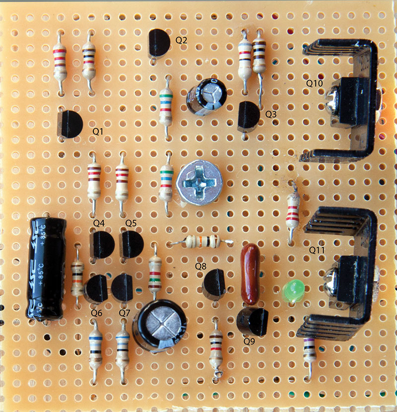
FIGURE 1. One channel assembled on perfboard.
Another less common error in wiring is to reverse the power supply voltages. Referring again to Figure 1, the positive supply is at the top and negative is at the bottom.
POWER SUPPLY CONSIDERATIONS
Regulated power supplies are a totally unnecessary complication in this project. A well designed amplifier done with power supply rejection in mind doesn’t care about precise power supply voltages. Power supply rejection (the ability of the amplifier to ignore ripple voltage and changes in supply voltages) is excellent in these amplifiers. I tend to use perfboard for prototypes (also referred to as Vector board for the name of the manufacturer). The holes are at 0.1” centers which is convenient for placing parts.
For this headset amplifier’s power supply, I suggest an 18 volt center-tapped transformer. The rectifiers (1N4001s) are very inexpensive and widely available. The filter capacitors can be found at several surplus places.
GETTING HOOKED UP
Output voltage will be about ±12 volts — perhaps a little higher with no load. Connect the ground ends of the two filter capacitors very solidly and run a short bus off of them. Connect the center tap of the transformer here. This will be the “quality ground” for the amplifier.
The amplifier ground will connect to this point using ordinary hookup wire. The headset ground return should be to this point, as well. Headset wiring doesn’t need to be anything special. Ordinary hookup wire will be fine.
Of course, you will want to connect a headset jack to the output.
CONSTRUCTING THE AMPLIFIER
Small transistors in Figure 1 with the flat to the left are PNP 2N5401; the ones with the flat facing right are NPN 2N5551. These are available at more than one of the sources listed here. I recommend purchasing a supply of each of these types.
The voltage rating is much higher than needed here, but they can be used in other higher power amplifier designs, as well. I saw the NPN for about four cents each in 100 lots. The PNP was more like five cents.
Shorting the output to ground won’t blow up the amplifier. If the amplifier does suddenly output the full power supply voltage, it won’t (in general) wreck a pair of headphones, but don’t poke or probe at the amplifier with the headphones connected anyway. That is simply asking for trouble.
The overall amplifier is DC coupled. For safety, since a device connected to the input might have a DC voltage on its output, a coupling capacitor is used. One 22 µF non-polar capacitor or a pair of regular polarized capacitors back-to-back can be used (also 22 µF).
This input coupling capacitor (or capacitors) protect the amplifier in case a substantial voltage is accidently attached to the input. This makes the lower 3 DB response frequency about 3 Hz. Since we can’t hear much below 20 Hz, this is more than adequate.
Construction is easy on a piece of perfboard. Place the parts as they appear in Figure 2 for easy checking of the wiring when you are done. I generally use component leads to make interconnections on the back of the board and wire-wrap wire for connections where the wires are not long enough, or wires have to cross each other. I always solder them. The wire is thin and has thin insulation, making it easier to work on the board. However, if you nick the conductor when stripping the wire, it can break easily so be careful.
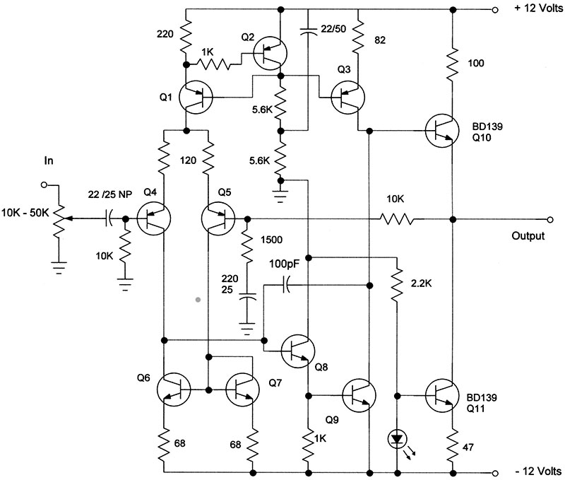
FIGURE 2. Amplifier schematic.
| Transistors |
| Q1-5 2N5551 NPN |
| Q6-9 2N5401 PNP |
| Q10-11 BD139 |
| Resistors - All 1/4 watt 5% carbon film |
| Electrolytic capacitor voltages as marked. The 100 pF capacitor must be mica or NPO ceramic. |
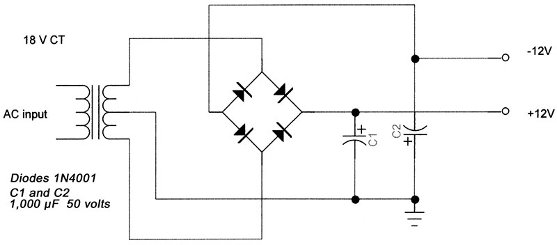
FIGURE 3. Power supply schematic.
Observe the proper polarity of the LED. The one I’ve used has one longer lead which is the positive one, i.e., the anode. You might want to test an LED and the 2.2K resistor connected to a 12 volt power supply to be sure you have the right polarity.
Check the voltage across the LED. It needs to be about 2.1 volts. Different colored LEDs have different forward voltages, so you might have to try a few different types. These devices make very good voltage references. You can place one on the front panel of a box if you decide to build two channels and package them.
TESTING
Don’t connect the headset yet. Solid-state amplifiers are comfortable with no load. DON’T just connect and turn on the power when you are done. With a multimeter, check the resistance from each power supply lead to ground one at a time. Resistance less than 1K ohm or so indicates a problem.
Trace your wiring carefully to catch omitted wires, untrimmed resistor or capacitor leads, and/or accidental solder bridges. If the board is laying on your workbench, be sure there are no scraps of resistor leads or tools under the board. Short circuits need to be avoided if the circuit is to have a chance to work. I’ve had a circuit blow up due to a resistor lead on the bench.
When you apply power, note that the LED lights. If the output transistors get more than just slightly warm or if the 100 ohm resistor in series with the collector of the output transistor gets hot, you’ve done something wrong.
Assuming no smoke, measure the output voltage to ground. If it is not within 20 or 30 millivolts, there is a problem. My breadboard circuit measures close to 0 mV. If your voltmeter doesn’t go down that far, set it to the 20 volt or more range, then connect it between output and ground. If the needle doesn’t move, switch to successively lower ranges. On a one volt range, you might see the needle move a little.
Assuming low voltage, connect an audio source to the input. A CD or MP3 player is convenient. If you have a scope, connect it to the output and adjust the volume control for a few volts peak-to-peak output and note that the peaks are not clipped.
HEADSETS
Headsets come in a variety of impedances and sensitivities. A search on the Internet found headsets with impedances from 600 ohms all the way down to 24 ohms.
This amplifier is current-limited at the output. It should not damage any headset due to high signal levels and the output is protected against a short circuit. High-end headset users worry a bit about the damping factor. (In an audio system, the damping factor gives the ratio of the rated impedance of the loudspeaker to the source impedance.)
The amplifier has very low output impedance and provides a high damping factor for any headset. If you have a low impedance set, be aware that the volume control must be turned to a low level. I’ve left the gain high to accommodate high impedance headsets. Thanks to a friend, I’ve tested the amplifier with 32 ohm, 60 ohm, and 300 ohm headsets.
This design is capable of considerable power in terms of what a headset needs. It was made this way so it can accommodate a wide variety of headset impedances. Set the volume at a reasonable level. Audio is not much of a hobby if you damage your hearing! If you have done everything correctly, you should hear clean audio. The amplifier clips at an output of around 35 mA peak. This is no problem in terms of the signal required to drive a headset to high volume. Now, all you have to do is build a second channel, and mount the amplifiers and power supply in a suitable project box. Once securely mounted, it will be very reliable.
Measured distortion at three volts out at 20 Hz on up to about 1 kHz is 0.0012%. It changes very little from no load to a couple hundred ohms. I have a Hewlett-Packard 339A distortion test set that includes a very low distortion signal generator and the analyzer. It measures total harmonic distortion plus noise (THD+N). The 339A measures 0.0012% when the signal generator output is connected directly to the analyzer input; that is, the reading is the same with the amplifier as it is without it.
Distortion at 20 kHz measures 0.0021% with a 1K load, rising to about 0.008% with a 100 ohm load. Distortion will depend on the impedance of your headset and the sensitivity. More sensitive headsets require less input power and will have less distortion.
Readings are obviously very near the limit of the capability of the analyzer. The normal listening level will be about 0.3 to one volt AC at the headset. Response is down 3 DB at around 600 kHz. Response must go far beyond audio frequencies in order to insure that there is enough negative feedback at 20 kHz to reduce the distortion to a low level. (This topic deserves an article by itself.)
I think it is fairly safe to say that distortion will be less than 0.01% over the audio frequency range at normal to loud listening levels with nearly any reasonable headset. Distortion depends somewhat on construction techniques and on individual transistor characteristics.
Remember next month, we will discuss the theory of this headset amplifier design. Happy listening! NV
PARTS LIST
| QTY |
|
POSSIBLE SOURCE |
| Power Supply |
| 1 |
Transformer 18 volts CT at one amp |
Marlin P. Jones |
| 4 |
1N4001 rectifier diodes |
|
| 2 |
1,000 µF 25 volts or more |
|
| Amplifier |
| Resistors all 1/4 watt 5% carbon film |
| 1 |
47 |
|
| 2 |
68 |
|
| 1 |
82 |
|
| 1 |
100 |
|
| 2 |
120 |
|
| 1 |
220 |
|
| 2 |
1K |
|
| 1 |
1500 |
|
| 1 |
2200 |
|
| 2 |
5600 |
|
| 2 |
10K |
|
| Transistors |
| 5 |
2N5401 |
Tayda |
| 4 |
2N5551 |
Tayda |
| 2 |
BD139 |
BG Micro |
| Capacitors, electrolytic |
| 1 |
22/50 |
|
| 2 |
22 at 25 or one 22 at 25 non-polar |
|
| 1 |
220 at 25 |
|
| Capacitor, ceramic NPO or silver mica |
| 1 |
100 pF at 25 or more |
|
| Miscellaneous |
| 1 |
Perfboard 0.1 in hole centers |
Jameco |
| 2 |
TO-220 heatsinks |
|
| 1 |
Dual ganged potentiometer, 50K linear (for two channels) |
Tayda |
| |
Stereo headphone jack, your choice to match your phones |
| |
Power switch |
| |
Fuse 1A |
| |
Project box |
Jameco |
| |
Line cord |
| 2 |
RCA jacks for input |
SUPPLIER DETAILS
All Electronics — Van Nuys, CA. Has resistor and capacitor kits with a number of values.
www.allelectronics.com
Allied Electronics has a good selection of transformers.
www.alliedelec.com
B&D Enterprises has hard-to-find semiconductors.
www.bdent.com
BG Micro is in Garland, TX. They have surplus capacitors, diodes, etc. The BD139s are available at BG Micro for about 40 cents each.
www.bgmicro.com
Digi-Key is in Thief River Falls, MN. They seem to have everything.
www.digikey.com
Jameco, in the San Jose, CA area, tends to cater to hobbyists. Vector board is available at Jameco.
www.jameco.com
Marlin P. Jones in Florida has a good selection of transformers. They have one rated at one amp for $4.95. Your local RadioShack may have one for about the same price if you include shipping charges.
www.mpja.com
Mouser is more of an industrial supplier but has a lot of good stuff.
www.mouser.com
Tayda has the 2N5551 and 2N5401 for very low prices. Note this supplier is in Bangkok, Thailand but the prices are very low and shipping is not costly if you are not in a hurry. I receive orders from them in less than 10 days. They have a limited selection of items.
www.taydaelectronics.com