If your pastimes include fiddling with microcontrollers, then you’ve probably already experimented with sensing light, temperature, humidity, infrared, touch capacitance, and so forth. Have you ever considered brewing up a circuit that will respond to sound?
This is a fun project with lots of unusual applications in the areas of home security and remote control. For example, the module to be described here could be used to detect breaking glass, thunder claps, barking dogs, or a baby crying. It can even detect explosions or gunshots should you dwell in that sort of environment.
The application I originally had in mind is a little more down to earth: a circuit that responds intelligently to handclaps and then controls outboard equipment.
Called the Sonic Sensor, it can directly drive digital circuits such as CMOS counters or common timers for more advanced responses. Even better is hooking it up to a PIC, Arduino, or other processor, and letting the software work some additional magic.
To keep things concrete for the moment, let’s suppose our task is simply to sense handclaps and then control various appliances when detected. You’re probably already smirking, thinking of cheesy commercial novelties you’ve seen before. (Heck, I even ran across such a unit in the close-out bin of a RadioShack some 25 years ago.) More recently, a number of reviewers have complained about the usability of clapping switches on Amazon.
The Sonic Sensor deals with the reliability issue nicely, and pairing the device with a microcontroller opens up the possibility of even more exotic options.
Theoretically, detecting handclaps should be easy. The amplitude envelope of a microphone is preamplified, rectified, and filtered, and then a comparator trips whenever a certain threshold is reached. Unfortunately, various practicalities make this undertaking surprisingly difficult, and the tradeoffs must be carefully balanced to arrive at a truly useful gizmo. In fact, I went through three distinct revisions and topologies before arriving at a trustworthy circuit! As a first step, let’s see what the design goals are.
The Sonic Sensor should:
- Have adjustable sensitivity.
- Be fast but not prone to ripple in the filtered envelope.
- Provide a gate output when sound is detected.
- Operate on +5V for easy interfacing with microcontrollers.
- Be small enough to build as a plug-in unit for use with breadboards, yet be as simple and inexpensive as possible.
It took some doing, but these goals were nicely met. Shall we see how it works?
Theory of Operation
Refer to Figure 1 which shows the schematic. After a couple false starts, I elected to go with a discrete design which keeps the unit small, but more importantly, is easy to run on a unipolar power supply. An electret microphone is used as the sensor. These are active devices, with R2 providing the bias from the power supply.
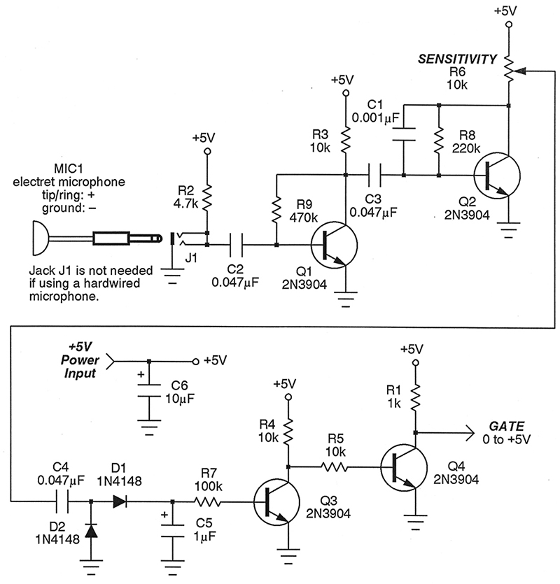
FIGURE 1.
Notice, however, that capacitor C2 blocks the bias voltage from later stages, while allowing the AC audio signal to pass. I picked up the parts for this project as surplus from All Electronics (www.allelectronics.com), including the electret microphone. If you’d like, you could use an external microphone on a cable with plug, but I went with a soldered-in unit.
The audio signal appearing on the far side of C2 is quite miniscule at this point — less than five millivolts — so we’ll have to preamplify it. Q1 and associated components carry out that job. The larger signal is then chained to a second preamplification stage configured around Q2.
Both of these stages thus far (Q1 and Q2) are extremely primitive, but why open a can of beans with a stick of dynamite? They get the job done, and niceties such as temperature compensation, flat response, low noise, and the like simply aren’t important when detecting handclaps.
Since the gain is moderately high in both, spurious oscillation is always a possibility. So, feedback capacitor C1 is plopped in place to damp it out if it tries to rear its ugly head. The total gain is around 1,200. Thus, a weak microphone signal has now become a much beefier three volts or so.
Sensitivity is dialed in by means of potentiometer R6. The tamed signal is passed on to the simple half-wave rectifier. D2 dumps the negative half of the waveform to ground, while D1 passes the positive portion on to C5. If you’d like, you can think of this capacitor as a low-pass filter. Or, if you prefer, as a peak detector. Either way, a DC voltage proportional to the microphone’s amplitude envelope is routed to Q3 which more or less switches on for larger signals.
The transistor may not saturate completely and also inverts the DC voltage, so we’ll send its output to Q4 which is a true switch now. The output becomes a solid gate, swinging smartly from 0V to +5V whenever the amplitude set by R6 exceeds a certain level.
You might think this is all too ingenuous to get the job done, but keep in mind we’re just trying to sense bursts of noise and simply want a digital output: on or off. For these reasons, there is no need to call out the heavy artillery. All of the usual headaches like response time versus ripple, resolution, and the like are of no real concern.
Build It in an Evening
The Sonic Sensor is a snap to build and a nice one-night project for DIYers at any level of experience. None of the parts are hard to find, nor are there any special construction concerns. It could easily be assembled on a piece of stripboard, but I prefer to use homemade printed circuit boards (PCBs). Since this affair weighs in at a diminutive 1-1/4 by 2-1/2 inches, that undertaking could even be tackled with nothing more than a small bowl of etching solution.
I got the job done (from artwork design to an etched and drilled board) in a couple hours just working with a slapdash system out of my kitchen. Figure 2 shows the PCB artwork I used, while the parts placement guide appears in Figure 3.
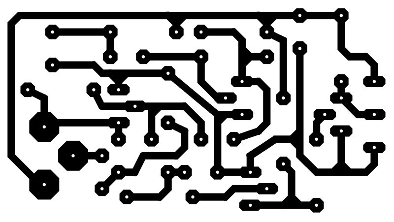
FIGURE 2.
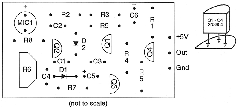
FIGURE 3.
Figure 4 is a photograph of how my unit ended up.
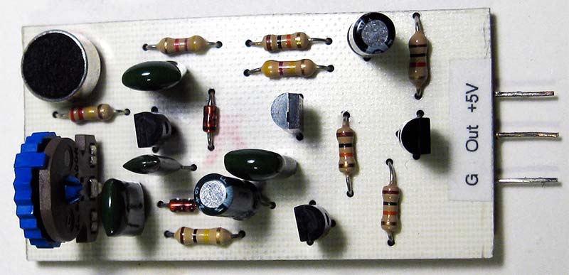
FIGURE 4.
Here are a few notes of interest to guide you along.
As mentioned earlier, I went with a soldered-in microphone; you’ll spot it in the upper right-hand corner. Next to it is a thumbwheel type trimmer potentiometer (R6). Any type of pot is useable here, though. If you’d prefer to build the thing in a small box with a panel mount control, go for it.
I wanted to be able to use the Sonic Sensor on a breadboard and so utilized pins for ground, +5V, and output spaced in increments of 0.100 inches. I even went one step further and spread them out every other pin so the device would fit into the multiples of the DIY PIC Trainer I wrote about in a previous article. You’ll see it installed on the Trainer in Figure 5.
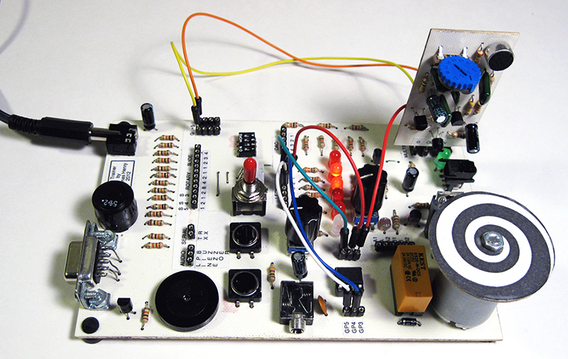
FIGURE 5.
A plug-in module sure makes life sweet for some rapid deployment of ideas!
Using the Sonic Sensor
I suppose you could connect the Sonic Sensor directly to a driver transistor and relay to simply switch some apparatus on as long as a sound is present. That doesn’t sound all that useful to me, though, since latching is probably what you want.
A better idea would be to use it to fire a 555 timer acting as monostable. When a burst of sound comes in, the timer goes on for a specified interval and then shuts off again. If you’re going this route, remember that the 555 responds to a negative-going edge, so you’ll probably want to differentiate and invert the output gate with, say, a simple transistor affair.
So, maybe you’d like to count handclaps or other sounds. That’s easy to do. Just hook up the Sonic Sensor to some sort of CMOS counter like the 4017, 4024, 4026, 4511, or countless (groan …) other such devices available. You could light a 10-element LED bar graph or perhaps a seven-segment LED display to show the number of bursts detected.
With the Sonic Sensor taking care of providing a gate or rising edge to fire a CMOS flip-flop or counter, the sky is the limit on what you can come up with.
For the most versatile approach possible, consider connecting it up to a microcontroller. The firmware can then do all sorts of things like count pulses, take averages, monitor intervals between bursts, check the clock times the sounds occur, route the results to buzzers, relays, motors … you name it.
Just as one offhand example, suppose you own a summer cabin but don’t expect to be there for several months. You could come up with a circuit that turns on floodlights whenever any crashing sound is heard (breaking glass, forced entry through a door, etc.).
Back to handclaps. I’ve provided two PIC12F683 programs written in the free and open-source Great Cow Basic language that are really pretty interesting; get them in the downloads for this article. The first simply bumps a counter for each clap of the hands, showing the current count on some LEDs in binary.
The second program is even fancier and will start counting as soon as you start clapping, then stop the count when you stop. With this, you could control a large number of devices. For example, clap once and a lamp turns on. Clap twice and it turns off. Clap three times and the radio turns on; clap four times and it turns off again. You can keep going like this almost indefinitely (limited only by the port pins of your microcontroller).
Unlike those commercial units of yesteryear, you now have the ability to put a large number of appliances under sonic control. The sample programs are heavily commented and also give any hookup instructions to the LEDs and so forth. Note too that the programs utilize one of the PIC timers in case you’ve ever wanted to learn more about them.
When testing my unit, I found I could get it to reliably count handclaps at a distance of up to 30 feet with the sensitivity set on max. Plus, it shouldn’t really be any great hurdle to port the sample programs over to an Arduino should that be your weapon of choice.
Safety Safety Safety
One final thing before I turn you loose to whip up you own applications. Controlling AC devices like lamps, radios, televisions, etc., is serious business. So, be safe! Use properly implemented opto-couplers and relays to isolate the Sonic Sensor from any 110 VAC apparatus.
Now, what cool application can you come up with? NV
Parts List
| Resistors All fixed resistors are 1/4 watt, 5% values. |
| R1 |
1K |
| R2 |
4.7K |
| R3-R5 |
10K |
| R6 |
10K trimmer |
| R7 |
100K |
| R8 |
220K |
| R9 |
470K |
| Capacitors Capacitors are 10V or better. |
| C1 |
0.001 µF mylar |
| C2-C4 |
0.047 µF mylar |
| C5 |
1 µF electrolytic |
| C6 |
10 µF electrolytic |
| Semiconductors |
| D1, D2 |
1N4148 diode |
| Q1–Q4 |
2N3904 NPN transistor |
| Other Components |
| MIC1 |
Electret microphone |
| Miscellaneous: Circuit board, solder, wire, header pins, optional jack, etc. |