Building a Camera Stick as a First Project
You’ve pillaged online blogs and articles for setting up your Raspberry Pi 3, but the information still seems scattered across sources, obfuscated by excessive fluff or just perplexingly puzzling. We hope the following guide is a clear and comprehensive alternative. Fingers crossed.
To give this setup tutorial some direction, we’re going to build a simple camera stick with the Pi camera which snaps a picture when a button is pushed. This is akin to a “Hello, World!” initiation for using a camera module with the Raspberry Pi. It teaches you how to set up the Pi, install a camera, use a couple General-Purpose I/O (GPIO) pins, and a smidgen of Python programming.
One more note before we dive into it. We’ve decided to highlight the subsequent text (in green) that is necessary for you to read to actually know how to do this. Cheers to all those who are really impatient or trying to get this done on a full bladder. The remaining un-highlighted text will be supplementary information for those who want a slightly more in-depth tutorial.
What you will need:
- A Raspberry Pi 3 (I’m using the Model B)
- MicroSD Card (recommended at least 8 GB)
- HDMI Cable
- Micro USB Power Supply (recommended 5V 2.5A)
- USB Mouse
- USB Keyboard
- Monitor (HDMI compatible)
- Wi-Fi
You can take a look at these required materials shown in Figure 1.
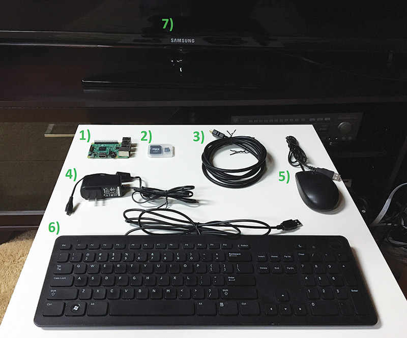
FIGURE 1. Layout of the required materials (Wi-Fi not pictured).
The microSD card is something that you might have laying around the house or can find at a local electronics store. You’ll need the microSD card adapter as well (the bigger SD card that the microSD card can plug into). You’ll use it to install NOOBS (New Out Of Box Software) which makes installing Raspbian — the preferred operating system for the Pi — a lot easier.
Note that an operating system is essentially the software of a computer that allows it to run basic functions. For example, you’ve probably heard of Windows 10 or remember those iOS updates for your iPhone. So, NOOBS is essentially software to help install other software.
Anyway, you can buy a microSD card with NOOBS pre-installed if you really want (refer to the Parts List), but we’ll learn how to install it onto a microSD card later.
The HDMI cable is likely a common household item nowadays. If you own a PS3 or an HDTV, they probably came with an HDMI cable. Otherwise, a quick search online should be pretty straightforward.
The micro USB power supply turns out to be something that most of us have seen before, as well. You can find an official RPi 3 power supply listed in the Parts List, but you can also use an old Samsung S3 charger or a portable phone charger. Since the Pi can run a relatively large number of peripherals, the idea is that you want to supply it with at least 2.5A (that is, amps) of power, but the alternatives suggested were only 1A each (enough for powering the Pi and a camera module). If you look at your charging device, you’ll usually find printed output values you can check (Figure 2).
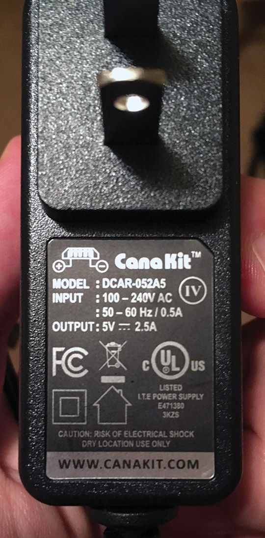
FIGURE 2. Look on the charger for the OUTPUT value(s).
The USB keyboard and mouse are the standard ones you likely have connected to your home desktops right now. Wireless keyboards and mice should work as well if they’ve already been paired.
Finally, if you know you don’t have a spare HDMI monitor, try checking the ports on your TV. Otherwise, you’ll want to look into finding a converter from VGA or DVI to HDMI.
Let’s get started! You’ll need to first install NOOBS on your microSD card. This installation consists of two major steps: formatting your microSD card; and actually installing the NOOBS files.
Insert your microSD into your computer that’s connected to Wi-Fi. You’re going to download a formatting tool provided by the SD Association (see Resources). If the link fails, simply go to sdcard.org and find the Downloads page at the top. Scroll down on the page and click the Accept button to begin downloading a zip file (Figure 3).
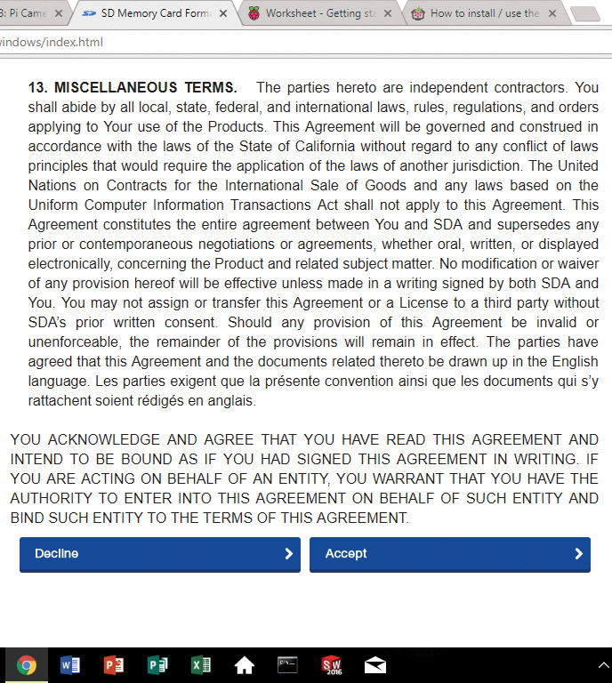
FIGURE 3. SD Formatting terms and conditions.
Once that has downloaded, open the file and click all the Yes and Next buttons the wizard throws your way. The SDFormatter tool should now be available for you to use.
Open it (if you have Windows 10, it should be in the Start menu). A window should appear that allows you to select the drive in which your microSD card is located (Figure 4).
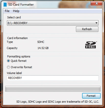
FIGURE 4. SD formatting tool window.
Once you’ve made sure to select the correct drive, click Format and OK on any subsequent prompts.
Now, let’s install the NOOBS files. Go to the Raspberry Pi downloads page (see Resources). If the link fails, a quick Google search works. Click on “NOOBS” and scroll down to Download ZIP for NOOBS (Figure 5).
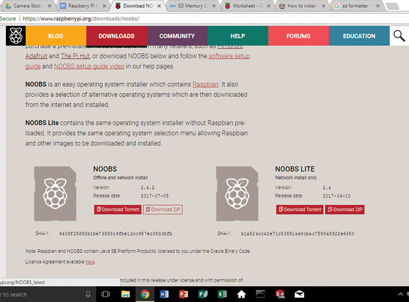
FIGURE 5. Downloading NOOBS zip file.
Once that has downloaded (this may take a while), copy and paste the files into your empty SD drive. When that’s done transferring, safely remove your microSD card from the computer. We’re now ready to begin booting up the Pi!
Insert the microSD card into your Raspberry Pi 3. Make sure that the orientation of the card is correct; if the Pi is facing up (with the USB ports on top), then the SD card slides in with the print facing down and the copper contacts facing up (Figure 6).
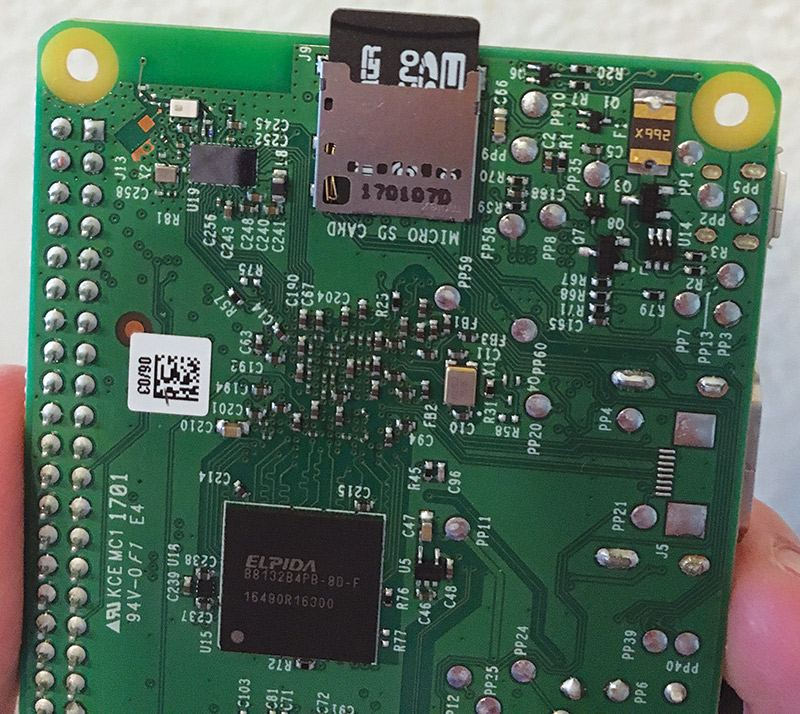
FIGURE 6. Inserting the SD card.
Notice this is a friction fit. In other words, there won’t be a spring or an auditory click.
Choose any two USB ports to plug in your keyboard and mouse. Plug in the HDMI cable to the HDMI port on the Pi and the HDMI port on your monitor. Finally, plug in the micro USB power supply into the Pi. If it’s plugged in correctly and the microSD was set up properly, you should see a red LED light turn on the Pi, as well as a blinking green LED. Note that the Raspberry Pi 3 does not have a power switch, so plugging in the power supply automatically turns it on.
A quick tidbit about the LED lights. The red light is associated with the power supply. It should be on and steady when you’re using your Pi. This is in contrast to the green LED, which will blink intermittently as it signals whenever your Pi is accessing the SD card.
A multi-color screen should appear on your monitor (Figure 7), followed by some text at the top of the screen. Once an installation window appears, you’ll have the option to install Raspbian.

FIGURE 7. Multi-color screen when you boot up your Pi.
You also have the option to connect to your local Wi-Fi network at this point if you wish. To do so, click on “Wi-Fi networks (w),” select your network, and enter your password.
To install Raspbian, simply check the box next to “Raspbian [RECOMMENDED]” and click Install (i) (Figure 8).
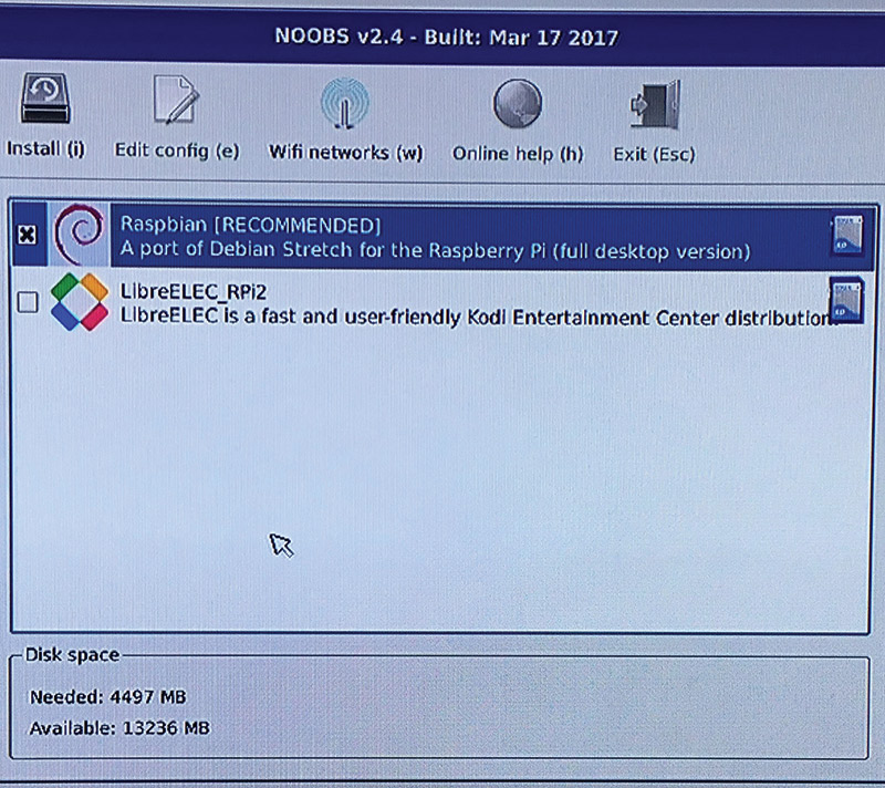
FIGURE 8. Installing the Raspbian operating system.
You’ll receive a Confirm window; click Yes to begin the installation. A window will appear with a progress bar at the bottom (Figure 9).
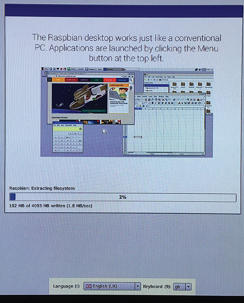
FIGURE 9. Raspbian Installation window.
This installation takes a while too (it took me a bit less than half an hour), but you are almost done!
Once the installation has completed, you’ll see an “OS(es) installed” window letting you know that the install was successful. Click OK, and the Pi will reboot. The monitor will go dark, followed by scrolling text. When the Pi has completely booted, the screen should resemble a familiar graphical desktop setting. From here, the final step is to configure your Pi settings.
Click on the Raspberry Pi button in the upper left corner; this opens the desktop menu bar. Find Preferences and click on Raspberry Pi Configuration (Figure 10). This opens the configuration window.
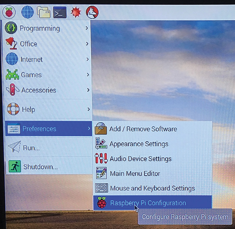
FIGURE 10. The Raspberry Pi task bar.
Click on the Localisation tab (Figure 11), and set your locale, time, keyboard, etc.
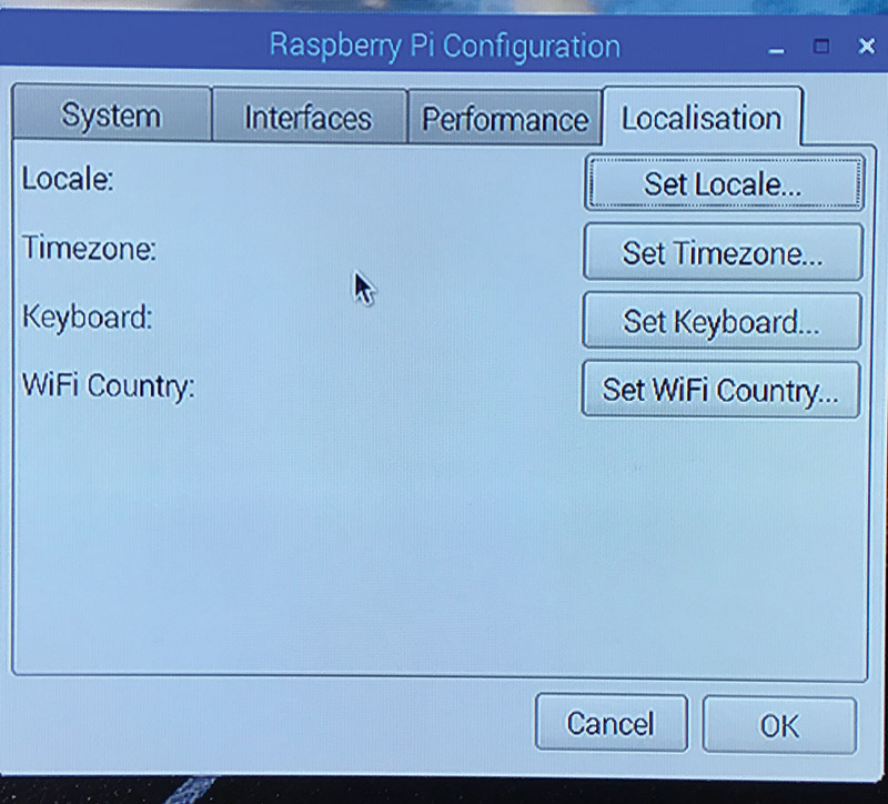
FIGURE 11. Raspberry Pi Configuration window.
When you’re done, click OK and Yes to the reboot prompt for the changes to take place. If you aren’t prompted, know that you’ll have to reboot the Pi for the changes to take place. Congrats! You’ve successfully set up your Pi!
If you didn’t connect to your Wi-Fi earlier, you can set it up from the desktop screen. Look to your upper right corner (typically) and locate the network button. It should be just to the right of the Bluetooth icon, and be an image of two computers. Click on it, select your local Wi-Fi network, and enter in the necessary password. If the Pi connects, the icon should change to radiating waves depicting one, two, or three bars.
Something else you’ll most likely encounter as you set off on your Raspberry Pi journey is the need to access and use the terminal. Accessing the terminal is simple: Click on the icon resembling a black box near the upper left-hand region of the screen. A terminal window appears (Figure 12). Here, you can control your Pi through various text commands and flirt with that hacker persona inside of you. Refer to the sidebar on Extra/Commands for how to get started with some of the basics.
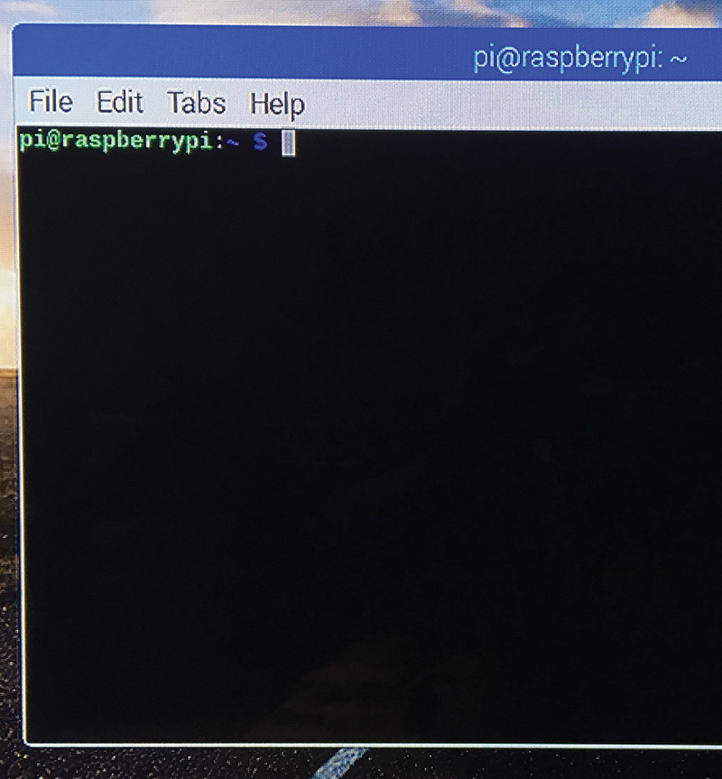
FIGURE 12. The Raspberry Pi Terminal window.
How is this even remotely possible?
The standard Raspberry Pi setup with a connected USB mouse, keyboard, and monitor isn’t always convenient. Luckily, there are two popular ways you can control your Pi remotely: Virtual Network Computing (VNC); or Secure Shell (SSH). They’re both relatively simple to set up.
Let’s take a look at VNC first. VNC allows you to control your Pi from a laptop or other computer through a graphical desktop interface. In short, whatever appears on the monitor connected to the Pi will appear in real time on the VNC Viewer on your laptop. In addition, a virtual desktop interface is created when you run a headless Pi, i.e., no monitor or graphical desktop.
Here’s how to connect to your Pi via VNC. Boot up the Pi, and open up the menu bar by clicking on the Raspberry Pi logo in the upper left-hand corner. Go to Preferences, then Raspberry Pi Configuration. A window should appear. Go to Interfaces and enable VNC if it isn’t already (Figure 13).
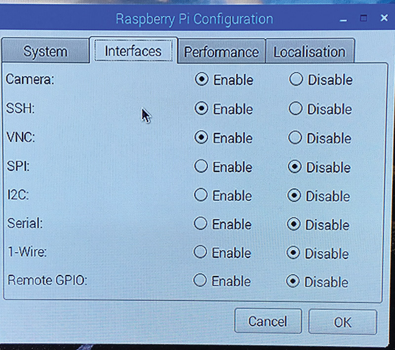
FIGURE 13. Enable VNC in the Configuration window.
After you “OK” the changes, the Pi may ask to reboot (if VNC wasn’t enabled). If so, reboot for the changes to take effect. When you get back to the home desktop screen, open up a Terminal window (the button looks like a black box at the top of the screen). Type in “hostname -I” to receive the IP address of the Pi, and remember this number.
Now you’ll need to download VNC Viewer from RealVNC on your laptop or computer (refer to Resources). Once that has downloaded, open it up to reveal a “VNC Viewer” window (Figure 14).
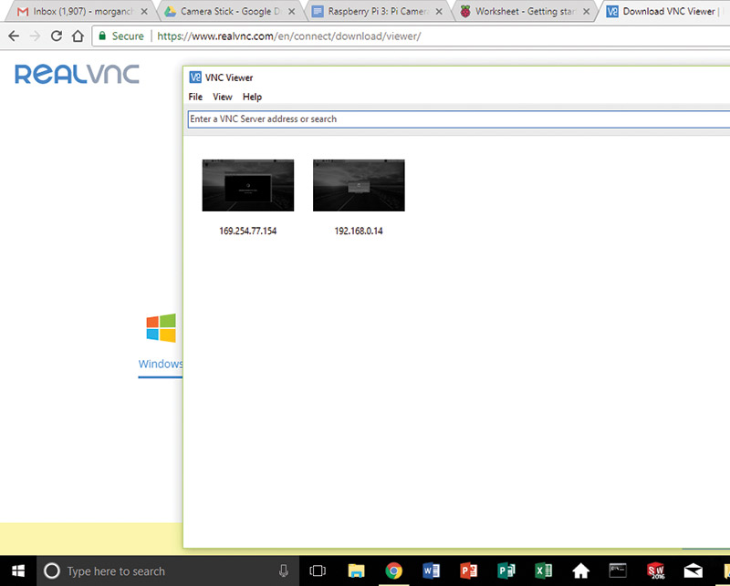
FIGURE 14. VNC Viewer window.
Enter the IP address into the top box. You’ll be prompted to enter in your username and password before you’re connected! If you didn’t change it, the default login is “pi” and “raspberry” for the username and password, respectively.
Now let’s switch our focus to SSH. The concept of remotely connecting to your Raspberry Pi is the same except you only have access/control via the terminal. In other words, you control your Pi with text commands instead of clicking through a graphical display.
We’ll be connecting to the Pi through a Windows computer in this SSH guide. If you’re using something other than a Windows computer, see Additional Content in the Resources list for directions. Just like with VNC, you’ll have to first enable SSH in your Raspberry Pi Configuration menu. To review: Menu > Preferences > Raspberry Pi Configuration > Interfaces. Ensure that SSH is Enabled. You can also use “hostname -I” in the terminal to return the IP address now. You will need this IP address later.
Similarly to how we used RealVNC for a VNC connection, we’ll be downloading and using a client called PuTTY (see Resources). Scroll down to where you see “putty.exe” in blue. If you’re not sure whether to download the 32- or 64-bit version, the 32-bit should run fine regardless. Download and run the file to open up a PuTTY Configuration window (Figure 15).
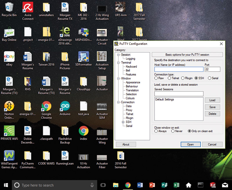
FIGURE 15. PuTTY Configuration window.
Type in the IP address into the “Host Name (or IP address)” field, and click Open. You’ll see a PuTTY Security Alert window which you can safely ignore by clicking Yes. Finally, the screen will prompt you for a username and password before you have access to your Pi. (Recall the default login is “pi” and “raspberry” for the username and password, respectively, if you haven’t changed it.)
Note that when you’re typing in your password to gain access via SSH, the cursor will not move and no characters will be displayed.
Take a picture — it’ll last longer.
As a small project with the Raspberry Pi, we’re going to construct a camera stick.
There is a great tutorial prepared by the Raspberry Pi Learning Resources listed in the Resources for using the camera module for the first time. It’s honestly about as clear and friendly of a tutorial as one can get, so I’ll only touch on some details that you might find helpful.
If your Raspberry Pi is fresh out of the box, there will be orange tape on the camera port and other display port. Note that the camera port is the one next to the HDMI port. Once you take off the tape, simply pull up on the ends of the wider black piece to open up the port. If it’s not obvious from the picture in the tutorial, you want to connect the ribbon cable so that the silver connectors are facing the HDMI port (Figure 16).
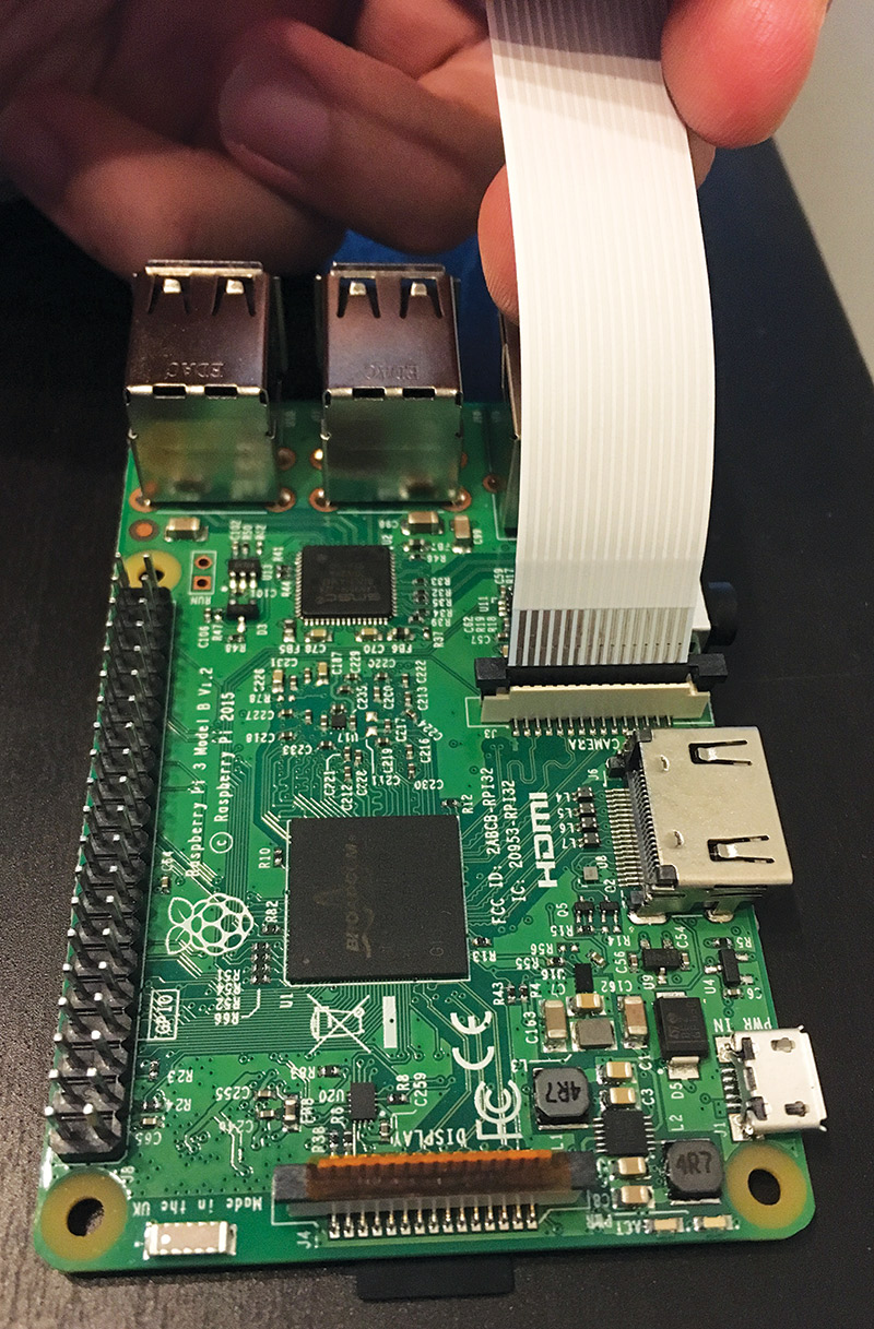
FIGURE 16. Inserting the camera ribbon cable into the Pi.
Gently push in the ribbon cable until it’s flush with the bottom of the board. Then, push down the black slider to lock the ribbon in place. This is a bit of a squeeze the first few times, and it’s easier to push down the slider one end at a time.
Once that’s in place, connect the other end of the ribbon cable to the camera module with the silver connectors facing the side with the camera lens (Figure 17).
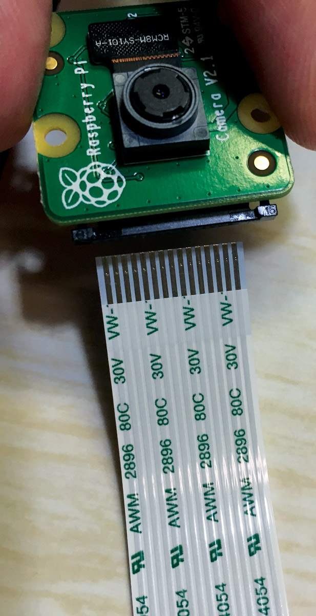
FIGURE 17. Inserting the ribbon cable into the camera module.
The mechanism is the same. You now have the camera connected and are ready to boot up the Pi.
The tutorial mentioned previously does a great job of introducing you to the functions and usage of the camera module — introducing programming in Python to capturing your first stills.
Perhaps another part of the tutorial that may warrant more of an explanation for a complete beginner is the code presented. While Python itself is a very readable language with friendly syntax, supplementary explanations may provide some benefit. Next is the first code you are instructed to enter into a Python file to run for the camera. Let’s quickly run through the lines:
from picamera import PiCamera
from time import sleep
camera = PiCamera()
camera.start_preview()
sleep(10)
camera.stop_preview()
The first two lines are importing functions from external modules, i.e., they are bringing in capabilities from other Python programs so that we may use these functions in the camera program we are creating. This saves us time and shortens the code we have to write.
The next line — camera = PiCamera() — is assigning a name to the PiCamera function that will be used to refer to this function. It’s similar to how one might refer to “Light Amplification by Stimulated Emission of Radiation” as simply “laser” in the sense that we are only assigning a name for the sake of simplification. The lines camera.start_preview() and camera.stop_preview() are functions that turn the camera on and off for you to get a preview of what you are capturing. These are functions that came from the PiCamera function you imported earlier. The line in between — sleep(10) — tells the camera to wait 10 seconds before executing the next line of code. Again, this was a function you imported from the time module at the beginning of the program.
Hopefully, this brief explanation gave a bit more insight into the workings of the code and also showed how friendly it can be to interpret and write Python.
One more thing I’ll add that the tutorial did not include. This camera setup is pretty straightforward and should work without a hitch due to its relative simplicity. In most cases, if you believe you’ve done everything correctly, any problems encountered are simple fixes.
So, if you run into any problems when you’re trying to capture a still, try the following:
- Make sure you inserted the ribbon cable properly on both the Pi and the camera. This includes ensuring that the cable is pushed in all the way.
- Some people believe it’s better to insert all the peripherals before you boot your Raspberry Pi.
- Make sure the power supply is sufficient (the red LED is steady), and the Pi is reading the SD card properly (the green LED blinks intermittently).
- If it’s a power issue, try using a different power source; if it’s the SD card, try rewriting it or using a different one.
- Make sure that your Raspberry Pi is updated. The commands for updating and upgrading your Pi are sudo apt-get update followed by sudo apt-get upgrade. (See Extra/Commands for details.)
- Updating your Pi is a good habit to get into regardless of whether or not you’re running into problems.
- Try rebooting your Pi.
- This can do the trick sometimes, and you may even decide to just come back to the Pi later in the day.
Just press the button. Don’t change the flash or anything!
What if we could take a picture with the Pi camera by pushing a button? Here is an easy tutorial to get you started on working with electronics and the GPIO header on the RaspPi.
Aside from your Pi and camera module, you’ll also need a tactile pushbutton, a breadboard, and female/male jumper wires. You can find these pretty cheap at local electronic shops, or you can consider the buttons, a half-size breadboard, and choose from a selection of jumper wires listed in the Parts List. For this small tutorial here, you only need a breadboard, one tactile button, and two female/male wires.
Take a look at your Pi. The GPIO header is the pair of columns of pins along the edge of the Pi. On the Raspberry Pi 3, there are 40 total pins with specialized functions that allow the Pi to be integrated to electrical circuits.
Refer to Figure 18 and the sidebar to familiarize yourself with the functions of each pin. This is a very powerful capability, and we’re going to start off with something very manageable to get you introduced.
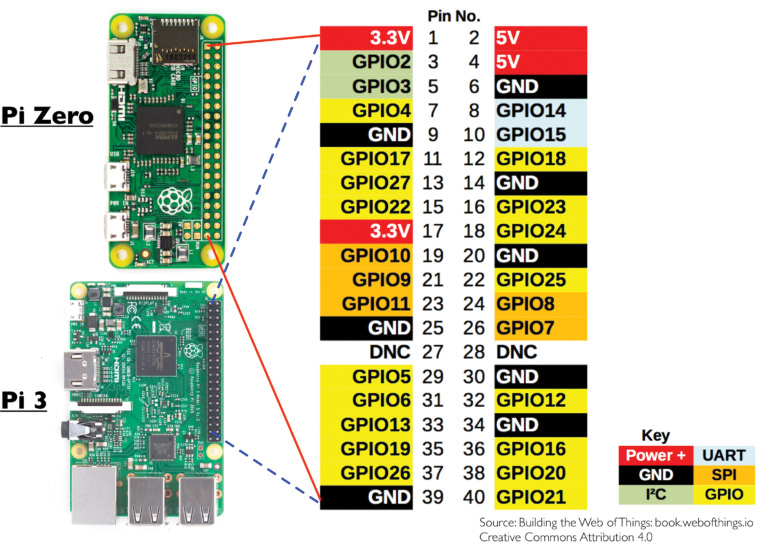
FIGURE 18. Pi 3 GPIO layout.
Perhaps it all seems cryptic and intimidating at first, but here is what you should think about for now. The 3.3V and 5V pins provide electrical power (where V stands for volts). Most of the remaining pins (such as GPIO02 or GPIO18) are ones you can use to output or read input in the form of electricity. The pins labeled “Ground” provide a return path for the electrical current. Numbering of the pins is done in the same fashion you read text in a book — left to right before moving down. You already have the code for capturing stills with the camera module. Let’s walk through how to set up the circuit and program.
Refer to Figure 19 and Figure 20 for the circuit. This is about as simple as it gets with the top wire connected to pin 6 and the bottom wire connected to pin 7.
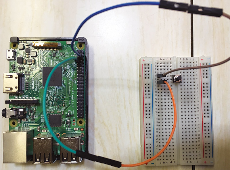
FIGURE 19. Connecting the pushbutton to the Pi.
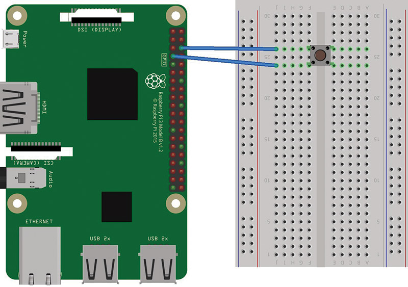
FIGURE 20. Fritzing diagram for connecting the pushbutton to the Pi.
Here are the basics of the program that we will use. Note that the program allows you to take one still photograph which it saves to the Pi desktop (see Resources). Let’s walk through it quickly so that you have an intuitive understanding of its contents:
import RPi.GPIO as GPIO
from picamera import PiCamera
from time import sleep
buttonPin = 7
buttonPress = True
count = 0
GPIO.setmode(GPIO.BOARD)
GPIO.setup(buttonPin, GPIO.IN, pull_up_down
= GPIO.PUD_UP)
camera = PiCamera()
while count < 1:
buttonPress = GPIO.input(buttonPin)
if buttonPress == False:
camera.capture(“/home/pi/Desktop/picture.jpg” count += 1
raise SystemExit
The first three lines should seem familiar to you (from the camera tutorial earlier). This program additionally includes importing modules that allow us to access and use the GPIO pins.
The next few lines simply set up and define some of the components that the program will be using. buttonPin = 7, count = 0, and buttonPress = True define variables; specifically, the number of the pin we are using to read input, how many stills you’ll take, and the state of the button (whether it’s being pressed or not).
GPIO.setmode(GPIO.BOARD) and GPIO.setup(buttonPin, GPIO.IN, pull_up_down = GPIO.PUD_UP) prepare the pins for use. The most important part here is that pin 7 is being coded to read input. You’ve seen camera = PiCamera() before.
The remaining code is the true meat of the program. It’s contained in a WHILE loop that reads the input from the tactile pushbutton to determine when to capture a still. The WHILE loop instructs the Pi to check for input continuously until you press the button.
The final line — raise SystemExit — exits the program when the still has been captured.
This explanation is somewhat cursory and passes over technicalities within the Python language, but you should now have an intuitive grasp of what the code is used for. If you’re squirming to know more, there are many free online resources to start writing Python on your own (refer to Resources).
And now, what we’ve all been waiting for ...
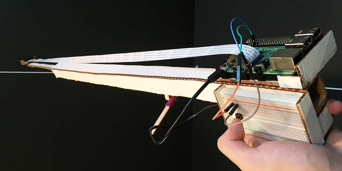
To really give this mini camera project some shape, you’ll want to consider crafting a camera stick. Find yourself some cardboard or other material of your choice, and let your creativity take over. Keep in mind what you’ll want to hold on to the camera stick: your Pi, camera module, mobile power supply, etc.
I went ahead and made a telescopic camera stick out of cardboard (Figure 21).
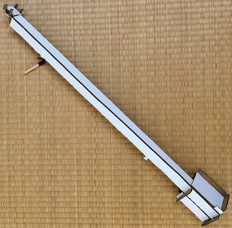
FIGURE 21. The cardboard camera stick.
An inner bar can extend by means of a simple thread pulley (Figure 22).
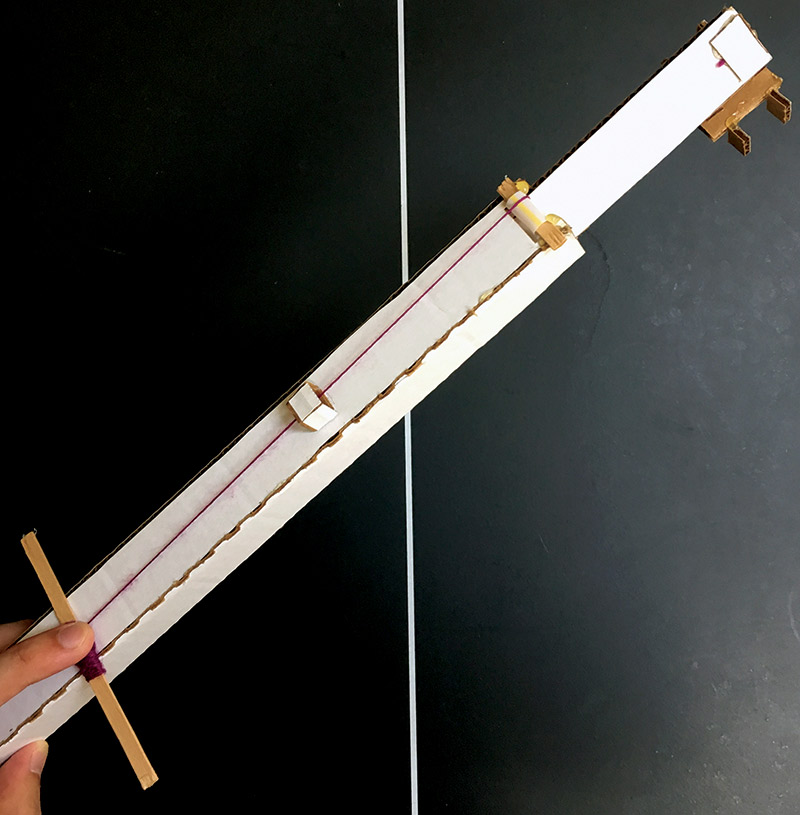
FIGURE 22. The pulley on the camera stick.
The Pi and mobile power supply are stored at the base of the stick (Figure 23).

FIGURE 23. The camera stick base.
Note that a one meter ribbon cable was used (Figure 24).
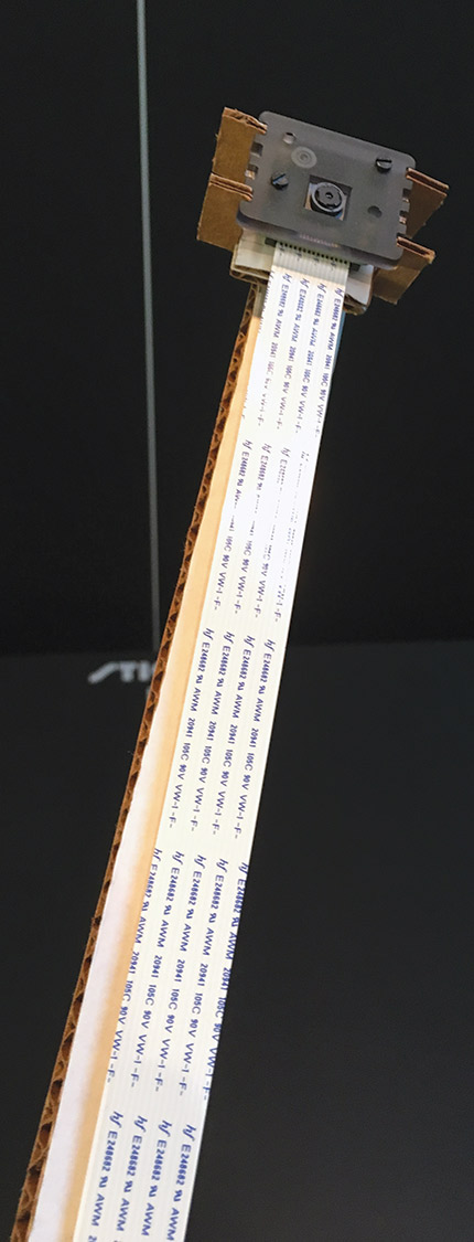
FIGURE 24. The camera module at the top of the stick.
By now, you should be able to take pictures with the Pi camera module (whether directly by code or with a pushbutton), and operate the Pi through a remote access method of your choice (SSH or VNC). Now, you just put it all together! NV
Extra/Commands
Here is a short list of general terminal commands that you may find immediately handy as you get familiar with your Raspberry Pi. Note that this list is not comprehensive.
- hostname -I: Gives you the IP address of your Pi.
- sudo raspi-config: Opens the Raspberry Pi configuration window.
- sudo apt-get update: Your Pi will retrieve the latest updates available.
- sudo apt-get upgrade: Your Pi will actually update/upgrade its system.
- sudo raspi-config: Opens the Configuration menu. Note this is the same menu that you can navigate to from the menu button with your mouse.
- sudo shutdown -h now: Effectively shuts down your Pi.
- pwd: Prints working directory; returns the name of the folder you’re currently in.
- ls: Lists the contents of the directory you’re in.
- lsusb: Lists the connected devices.
- cd [name of directory]: Changes the directory to whatever you type in.
- mkdir [name of directory]: Creates a new directory which you name.
Parts Sources
Pre-installed NOOBS SD Card
Search Amazon for options; here's one option.
Raspberry Pi 3 Power Supply
Title: CanaKit 5V 2.5A Raspberry Pi 3 Power Supply/ Adapter/Charger
ASIN: B00MARDJZ4
Price: $9.99
Link: https://www.amazon.com/CanaKit-Raspberry-Supply-Adapter-Charger/dp/B00MARDJZ4?ie=UTF8&*Version*=1&*entries*=0&tag=lifehackeramzn-20&ascsubtag=2e86c3caba68b74709ec13fa4b9d1ed0f1236d8f&rawdata=%5Br%7Chttps%3A%2F%2Fwww.google.com%2F%5Bt%7Clink%5Bp%7C1781419054%5Ba%7CB00MARDJZ4%5Bau%7C5716493564230329059%5Bb%7Clifehacker
Camera Module
Title: Raspberry Pi Camera Board v2 - 8 Megapixels
Product ID: 3099
Price: $29.95
Link: https://www.adafruit.com/product/3099
Tactile Pushbuttons
Title: Tactile Button switch (6 mm) x 20 pack
Product ID: 367
Price: $2.50
Link: https://www.adafruit.com/product/367
Half-size Breadboard
Title: Half-size breadboard
Product ID: 64
Price: $5.00
Link: https://www.adafruit.com/product/64
Female/Male Jumper Wires
Title: Premium Female/Male 'Extension' Jumper Wires
20 x 3"
Product ID: 1953
Price: $1.95
Link: https://www.adafruit.com/product/1953
Resources
SD Formatting Tool
https://www.sdcard.org/downloads/formatter_4/eula_windows/index.html
NOOBS Installation
https://www.raspberrypi.org/downloads
A video guide for setting up the Pi
https://www.youtube.com/watch?v=gbJB3387xUw
A video guide for installing NOOBS
https://www.youtube.com/watch?v=6VmlfO7wL40
VNC Viewer from RealVNC
https://www.realvnc.com/en/connect/download/viewer
PuTTY Installation
https://www.chiark.greenend.org.uk/~sgtatham/putty/latest.html
Additional Content (includes SSH for other OS devices)
For more details on VNC
https://www.raspberrypi.org/documentation/remote-access/vnc
For more details on SSH as well as using other OS devices
https://www.raspberrypi.org/documentation/remote-access/ssh/README.md
Getting Started with the Pi Camera
https://www.raspberrypi.org/learning/getting-started-with-picamera
Another video tutorial for taking a picture with the Pi camera
http://thezanshow.com/electronics-tutorials/raspberry-pi/tutorial-12
Another video tutorial on using the pushbutton
http://thezanshow.com/electronics-tutorials/raspberry-pi/tutorial-20
Another tutorial on setting up the pushbutton
http://razzpisampler.oreilly.com/ch07.html
A solid resource to begin learning Python
https://www.learnpython.org
Raspberry Pi documentation about the terminal and its usage
https://www.raspberrypi.org/documentation/usage/terminal
A more comprehensive list of terminal commands
https://www.raspberrypi.org/documentation/linux/usage/commands.md
Public Invention
The camera stick project is a part of Public Invention: a non-profit dedicated to open-source hardware invention in the public interest. To get involved with Public Invention, contact [email protected]. Our YouTube channel gives some idea of the kind of projects we are currently running. Most of our work is published at GitHub.
Accreditation
Pi 3 GPIO layout from "Building the Web of Things" (1) by Dominique Guinard and Vlad Trifa (2) is licensed under CC by 4.0 (3).
Links:
(1) https://webofthings.org/2016/10/23/node-gpio-and-the-raspberry-pi
(2) https://webofthings.org/team
(3) https://creativecommons.org/licenses/by/4.0/legalcode
Downloads
What’s in the zip?
Source Code
Software License