The sine wave is a naturally occurring signal shape in communications and other electronic applications.
Many electronic products use signals of the sine wave form. Audio, radio, and power equipment usually generates or processes sine waves. As it turns out, there are literally dozens of ways to generate a sine wave. This article presents some popular methods you should be familiar with.
Wien Bridge Oscillator
A popular low frequency (audio, and up to about 100 kHz or so) sine wave oscillator is the Wien bridge shown in Figure 1.
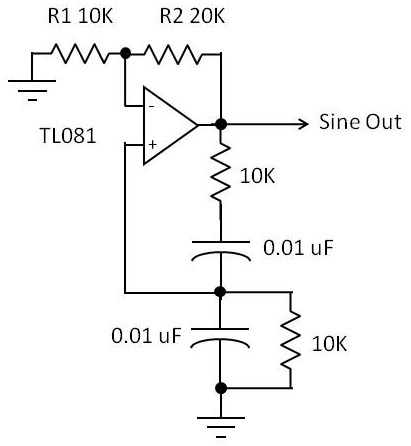
FIGURE 1. The popular Wien bridge oscillator. An oldie but goodie. Frequency can be varied by using pots for R and using different values of C switched in.
It uses an RC network that produces a zero degree phase shift from output back to the input, producing positive feedback that, in turn, produces oscillation. An op-amp is used to produce a gain of three that offsets the attenuation of the RC network. With a net closed loop gain of one, the circuit oscillates at a frequency determined by the values of the RC network:
f = 1/2πRC
This circuit works great and produces a very clean low distortion sine wave. Its problem is that instabilities in the gain and phase can cause the circuit to go out of oscillation completely, or go into saturation producing a clipped sine wave or square wave. Some compensation components are usually added to eliminate this problem.
A simple solution is to replace R1 with a small incandescent bulb whose resistance changes with current. As the output goes up, the bulb current and resistance increases, and reduces the gain to compensate. If the output goes down, the current decreases, lowering the resistance and increasing the gain to keep the output constant. One working example is to make R2 390 ohms and R1 a type 327 bulb. Other more elaborate schemes use an FET as a variable resistor to vary the gain.
This circuit works and has a frequency of about 1,592 Hz. Output amplitude depends on the power supply voltages.
Phase-Shift Oscillator
A popular way to make a sine wave oscillator is to use an RC network to produce a 180 degree phase shift to use in the feedback path of an inverting amplifier. Setting the gain of the amplifier to offset the RC network attenuation will produce oscillation. There are multiple variations of phase shifters, including a Twin-T RC network and cascaded RC high pass sections that produce either 45 or 60 degree shifts in each stage. The amplifier can be a single transistor, single op-amp, or multiple op-amps. Figure 2 shows one popular variation.
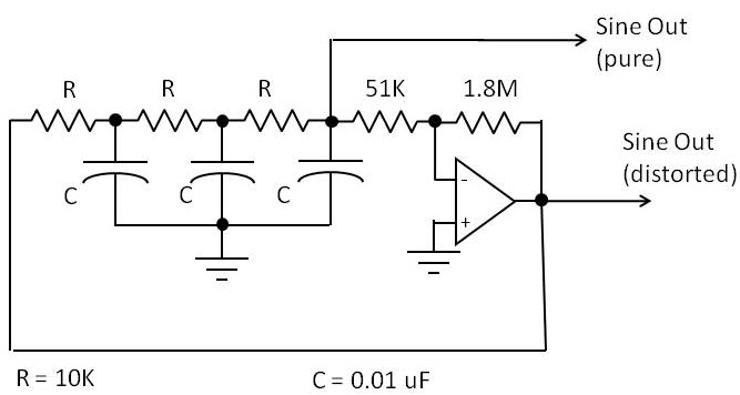
FIGURE 2. A fixed frequency is a disadvantage, but for a single frequency is good. The pure output needs to be buffered with an op-amp follower if you are going to drive a load.
These oscillators produce a very pure low distortion sine wave. However, the frequency is fixed at the point where each RC section produces a 60 degree phase shift. That approximate frequency is:
f = 1/2.6RC
In the circuit of Figure 2, the frequency should be about 3.85 kHz.
Colpitts Crystal Oscillator
Quartz crystals are often used to set the frequency of an oscillator because of their precise frequency of oscillation and stability. The equivalent circuit of a crystal is a series or parallel LC circuit. Figure 3 is a very popular sine wave oscillator of the Colpitts type, as identified by the two-capacitor feedback network.
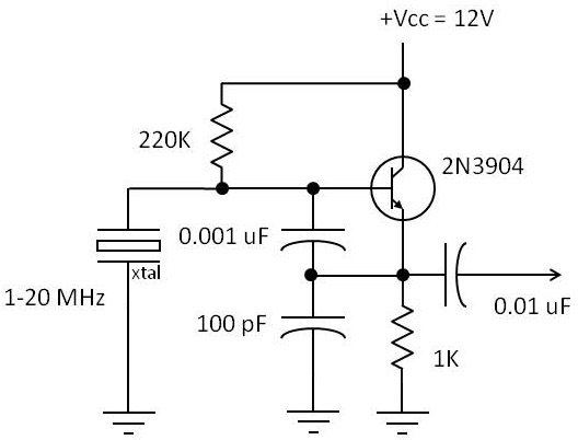
FIGURE 3. A popular crystal oscillator that works every time.
This is another widely used circuit because it’s easy to implement and very stable. Its useful frequency range is approximately 100 kHz to 40 MHz. The output is a sine wave with a slight distortion.
By the way, if you need a crystal oscillator with a sine wave out, you can usually buy a commercial circuit. They are widely available for almost any desired frequency. They are packaged in a metal can and are the size of a typical IC. The DC supply is usually five volts.
Square Wave and Filter
An interesting way to produce a sine wave is to select it with a filter. The idea is to generate a square wave first. As it turns out, it’s often easier to generate a square wave or rectangular wave than a sine wave. According to Fourier theory, the square wave is made up of a fundamental sine wave and an infinite number of odd harmonics.
For example, a 10 kHz square wave contains a 10 kHz sine wave, and sine waves at the 3rd, 5th, 7th, etc., harmonics of 30 kHz, 50 kHz, 70 kHz, and so on. The idea is to connect the square wave to a filter that selects the desired frequency.
Figure 4 shows one example.
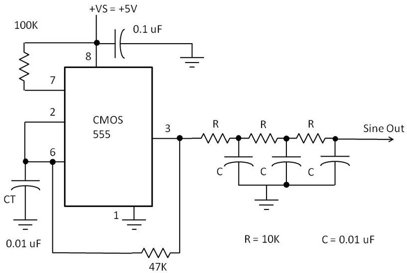
FIGURE 4. The CMOS version of the 555 is recommended, but you can make this work with a standard 555 by eliminating the 100K resistor.
A CMOS 555 timer IC produces a 50% duty cycle square wave. Its output is sent to a low pass RC filter that filters out the harmonics, leaving only the fundamental sine wave. Some distortion is common as it’s difficult to completely eliminate the harmonics. A more selective LC filter can be used to improve sine wave quality. Keep in mind that you can also use a selective band pass filter to pick out one of the harmonic sine waves.
This circuit is designed for a frequency of 1,600 Hz.
Direct Digital Synthesis
An interesting way to produce a sine wave is to do it digitally. Refer to Figure 5.
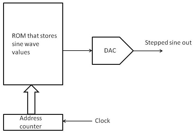
FIGURE 5. Direct digital synthesis.
It begins with a read-only memory (ROM) that stores a series of binary values that represent values that follow the trigonometry equation for a sine wave. These values are then read out of the ROM one at a time and applied to a digital-to-analog converter (DAC). A clock signal steps an address counter that then accesses the sine values in ROM sequentially, and sends them to the DAC. The DAC generates an analog output signal that is proportional to the binary value from the ROM. What you get is a stepped approximation of a sine wave.
Figure 6 is a crude example.
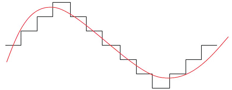
FIGURE 6. A stepped approximation of a sine wave. Passing the signal through a low pass filter will smooth out the steps.
If you use enough samples and use more bits for the binary value, the steps will be smaller and a more fine-grained sine wave will occur. The frequency of the sine wave depends on the number of samples or values you use for the sine wave and the frequency of the clock signal that reads the values out of the ROM. If the steps are too large, you can pass the stepped signal through a low pass filter to smooth it out. Special direct digital synthesis (DDS) ICs like those from Analog Devices are available to generate sine waves from below 1 Hz to many MHz.
Function Generator
A function generator is the name for a device that generates sine, square, and triangle waves. It may describe a piece of bench test equipment or an IC. One old but still good function generator IC is the XR-2206. It was first made by Exar in the 1970s, but is still around.
If you need a sine wave generator that can be set to any frequency in the 0.01 Hz to 1 MHz or more, take a look at the XR-2206. Figure 7 shows the XR-2206 connected as a sine wave generator.
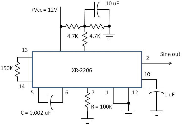
FIGURE 7. The XR-2206 is an older IC that is still available and a great way to generate sine, square, and triangle waves over a wide frequency range.
The frequency is set by R and C and is calculated with the expression:
f = 1/RC
The internal oscillator generates a square wave and a triangle wave. The sine shaper circuit takes the triangle wave and modifies it into a sine wave.
This is still a great chip. Besides the three common waveforms it generates, it can amplitude or frequency modulate them as well.
Pulse-Based Sine Wave Generators
There are several other clever ways to make an approximate sine wave from pulses and filters. One way is to simply add together two square waves of the same amplitude where one is shifted 90 degrees from the other (Figure 8). A pair of JK flip-flops driven from opposite phase clock pulses can produce the two square waves to be added.
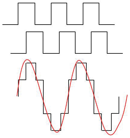
FIGURE 8. A crude way to make an approximation of a sine wave that may work for some AC power applications.
The result is a signal that can be used in some applications to replace a sine wave. Some crude DC-to-AC inverters use this method. The effect is an average power similar to what a sine wave would deliver to a load. Some RC or LC filtering can smooth the wave into a more continuous sine-like shape. This method is used in some uninterruptible power supplies (UPS) or solar power inverters where a perfect sine wave is not needed.
An interesting technique uses a sequence of varying width pulses that are filtered into a sine wave. If you apply a square wave with equal on and off times to a low pass filter, the output will be an average of pulse voltage over the on-off period. With a five volt pulse, the average output over the full cycle of the wave would be 2.5 volts. By varying the pulse duration or width, different average voltages can be produced.
An example is given in Figure 9.
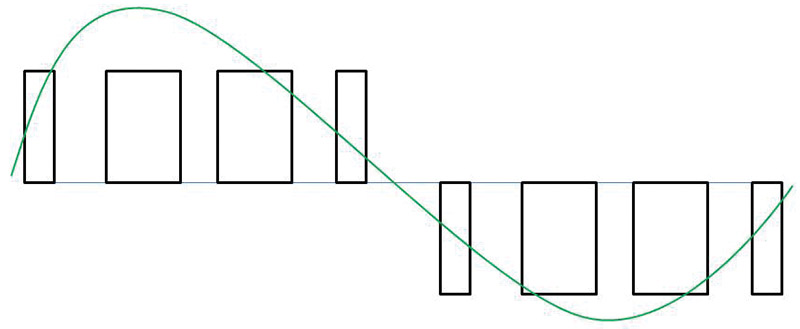
FIGURE 9. A PWM scheme to generate a pulse equivalent sine wave. Using multiple pulses reduces the harmonic distortion and averages into a smoother sine wave.
The pulse amplitudes are constant, but the pulse width or duration varies. As the pulse durations increase, the low pass filter produces a higher average output voltage. As the pulses get narrower, the average output voltage decreases. The load averages the pulses into a near sine. Using more pulses results in a smoother output sine wave. The pulses increase gradually and then decrease gradually, and their average is a sine wave. Additional filtering can be added as needed.
This technique is used in some variable motor drive systems to change the frequency of the sine wave applied to an AC induction motor to vary its speed (as with solar power inverters and uninterruptible power supplies).
The sequence of variable width pulses is usually generated by a microcontroller. Most of these processors have pulse-width modulation (PWM) instructions and one or more PWM outputs. The key to creating a low distortion sine wave is the selection of number, sequence, and pattern of pulses. Prolific engineer and writer, Don Lancaster developed a mathematical technique to determine the number of pulses and their durations to create a sine wave with minimum harmonic distortion. It’s called magic sine waves. Take a look at www.tinaja.com.
The circuits covered here do work if you care to play with them. I used a TL081 op-amp but almost any other works (741, etc.). It’s also a good idea to make the gain of the op-amp variable with a pot in the feedback path to adjust the gain to initiate or sustain oscillation. NV