This article started as an attempt to answer two questions posed in the Tech Forum here in Nuts & Volts. The questions were:
06192 - LED Fader, Cindi Carrillo
I need a simple method to slowly fade an LED from bright to dim, then to bright again in about two seconds, then keep repeating. Does anyone have a circuit that does not require an IC?
and
06193 - Transistor Confusion, Donald Bodine, Middleham, UK
What determines which type of transistor to use in a given circuit? Are they interchangeable with those of a different type that I may already have on hand?
The only relationship between these two questions is a transistor.
I’ll start by showing the two circuits I put together which demonstrate that — at least sometimes — one can use NPN and PNP transistors for the same task. I started with the very basic transistor schematics I found on https://www.electronics-tutorials.ws for the two types of bipolar transistors.
Specifically for the NPN, it was https://www.electronics-tutorials.ws/transistor/tran_2.html; for the PNP, it was https://www.electronics-tutorials.ws/transistor/tran_3.html.
I decided I’d use this information to build two circuits — one for the NPN and another for the PNP transistor — to simply drive an ultra-bright white LED. I came up with the test circuits shown in Schematics 1 and 2.
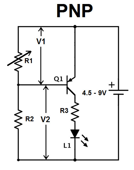
SCHEMATIC 1. Basic PNP LED driver circuit.
- R1 ~ 1K Ω Variable, On/Off ~ 287Ω/133Ω
- V1 ~ On/Off – 0.73V/0.02V
- R2 ~ 1.6K Ω
- V2 On/Off ~ 0.67V/-2.4V or -4.3V
- R3 ~ 510Ω
- Power Supply ~ 4.5V (not 9V)
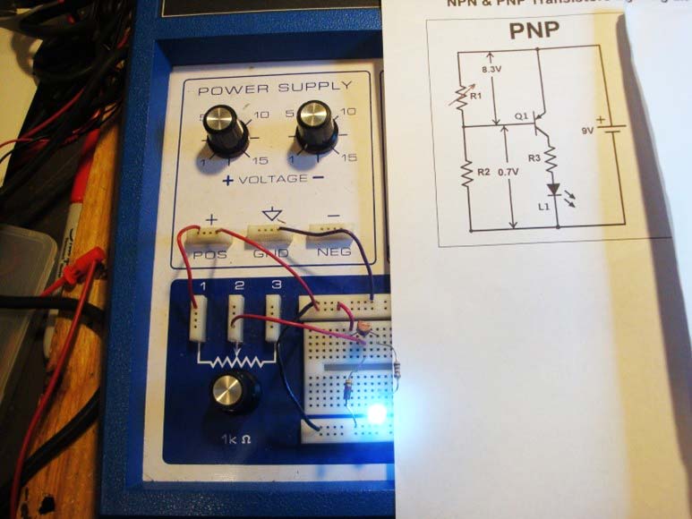
PHOTO 1. PNP LED driver.
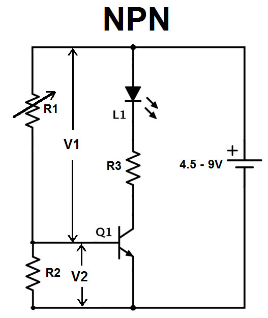
SCHEMATIC 2. Basic NPN LED driver circuit.
- R1 ~ 1K Ω Variable, On/Off ~ 96Ω/7.0K Ω
- V1 ~ On/Off – 0.70V/0.40V
- R2 ~ 1.6K Ω, volts
- V2 ~ On / Off ~ Not Measured
- R3 ~ 510Ω
- Power Supply ~ 4.5V (not 9V)
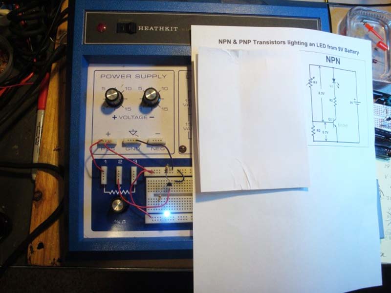
PHOTO 2. NPN LED driver.
These both worked just fine, though the values that worked best for the resistors were a bit different for each. I originally used 4.5 volts as the source and didn’t change the resistor values when I used nine volts. I standardized on nine volts because of two circuits I found for making a square wave and a sine wave:
- Q1 PNP = 2N3906 (I first tried a RadioShack Red PNP transistor, no other markings).
- Q1 for the NPN was a BC549CTA NPN bipolar SI transistor; I also tested 2N4401 and 2N3904.
NOTE: I was told by a friend that it would be better to put the variable resistor in the R2 position from the base to ground rather than in the R1 position. Can you figure out why? Here’s Clue 1: In this case, it really doesn’t matter, but in some other cases it definitely could. If you need it, here’s Clue 2: Think current.
If you use different transistors, you may have to use different R1 and R2 values. I used a 100 KΩ variable resistor for some transistors. The object is to get the 0.7V needed to turn the transistor on. Your experience may be different than mine. For more complex jobs, I found a site that helps one figure out which transistor should be used and why at https://www.controldesign.com/articles/2016/how-to-decide-between-pnp-and-npn.
While working on the above two circuits, I learned that an ultra-bright white LED can be made to fade on and off with different resistance values for R1. This led me to conclude that a simple transistor circuit could be made for the fade on/fade off circuit. However, the first circuit I put together came from an idea inspired by a beginner’s class held by Oyvind Dahl (his free beginner’s course is at https://www.build-electronic-circuits.com). I signed up for it to see if it was good for use with my grandchildren. In this class, he gave a very interesting use of an inverter. Another site he talked about and runs is https://ohmify.com. This is a membership site and costs money every year unless you join as a life-time member for ~ $500.
The Schmitt Trigger Inverter Circuit
The circuit in this class led me to using one inverter of the hex Schmitt trigger inverter (SN74LS14/ CD40106BE) to generate the square wave. Then, I followed that with a simple resistor-capacitor filter circuit to make something like a sine wave. In the end, I didn’t bother with a sine wave when I made it look something like a triangle wave. That worked fine for fading the LED on and off.
The capacitors were selected by testing out various values, and then working from there to increase the values until a good-enough triangle wave was the output to drive the LED at approximately the required period/frequency. The desired timing was to fade on and then off in two seconds. I listed the C1 capacitor value I used to get close to this in Schematic 3.
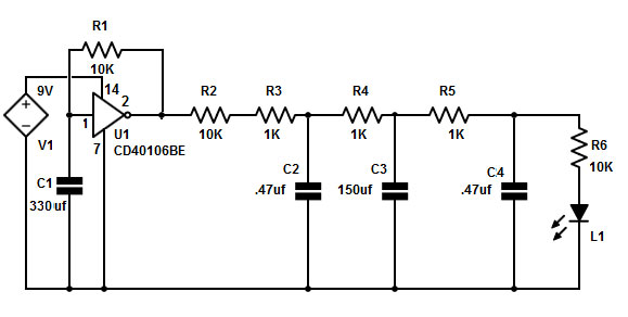
SCHEMATIC 3. Schmitt trigger inverter driven fade on-off circuit.
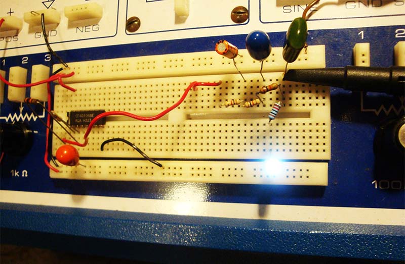
PHOTO 3. Schmitt trigger inverter fader.
VIDEO 1. SimpleLED_Fader.MPG.
The next circuit uses a 555 timer IC for the square wave. A quick note about the 555 chip: I always have problems with this chip when I use a proto strip to test the circuit. I can never get the off time of the square wave close to the same time as the on time. If I build the circuit and have a plug-in for only a capacitor, it works as desired with almost equal on and off (1 and 0) times. We need close to the same times for on and off so that we have time to make the LED fade on and off in about the same amount of time (one second for each fade) so that it looks good. The circuit used is shown in Schematic 4 with the capacitor value needed for getting close to a two second fade on and off time.
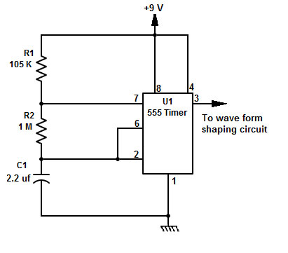
SCHEMATIC 4. The 555 circuit for a square wave.
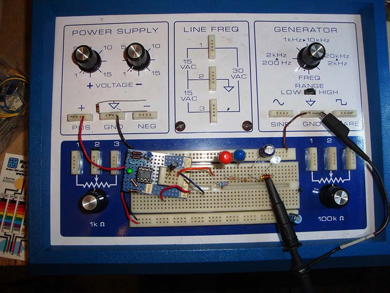
PHOTO 4. The 555 timer fader.
VIDEO 2. Simple555LED_Fader.MPG.
This circuit had a period of about two seconds. By this, I mean that it took about two seconds to cycle through off to full on to off again. For the wave-shaping circuit, I used the same general circuit used for the Schmitt trigger circuit but with different capacitor values. It’s shown in Schematic 5.
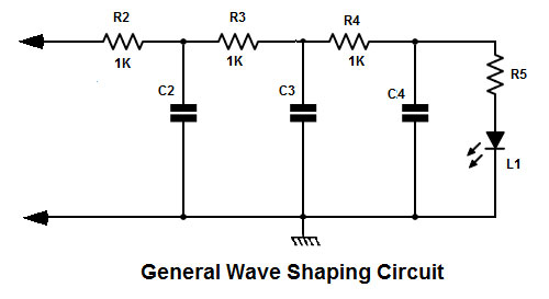
SCHEMATIC 5. General wave-shaping circuit.
For the 555 circuit the following values for the wave-shaping circuit were used:
R2, R3, and R4 = 1K Ω
R5 = 220 Ω
C2 = 100 µF
C3 = 150 µF
C4 = 100 µF
One Transistor Circuit
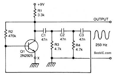
The last circuit was the one requested: a simple transistor oscillator circuit. This circuit used a 2N3904 NPN transistor and, again, some resistors and capacitors to get the timing close to the two seconds wanted. Note that the LED part of this circuit is very different from the other two circuits. This is because if you try to drive the LED directly from the transistor oscillator, the LED ends up sinking the signal needed by the transistor for the sine wave.
I could have added a second transistor LED driver circuit, but I wanted to see if I could come up with a one transistor circuit to form the sine wave, drive the LED, and not stop the oscillator from working.
To that end, I added a small cap and a much larger resistor in parallel to drive the LED and not cause the oscillations to die out and drive the LED close to its full brightness. I originally started with a 100 KΩ which was rather dim and reduced it down to a 10 KΩ resistor. That brought it back up to full brightness, at least as far as I could tell. Take a look at Schematic 6.
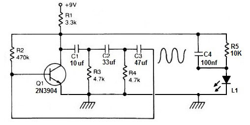
SCHEMATIC 6. The simple transistor fade on/fade off circuit.
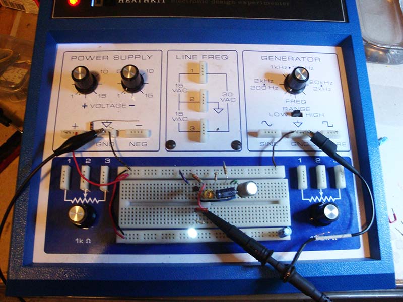
PHOTO 5. One transistor fader.
VIDEO 3. 1TransistorFader.MPG.
One More Thing
The sine wave and square to sine wave converter circuits can be found used in the fader circuits. Both of these were found online and used to produce the final fader circuits as needed. I mean that if you look at the simple one transistor fader circuit, you’ll be able to see the sine wave circuit in that circuit.
Then, I added parts to convert to a more triangle type ramp up/down in order to get a better fader effect. You can find these two circuits in Schematics 7 and 8.
SCHEMATIC 7. Sine wave circuit.
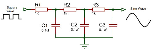
SCHEMATIC 8. Square to sine wave converter circuit.
None of these circuits should be considered an end product. They do what I wanted, but you may want to play with the values and/or add more parts to see if you can get the effect you want from the LED.
Conclusion
I hope this helps others who might be thinking, “I can’t do that,” when looking in Nuts & Volts for past articles which might help. Also, don’t forget to search on the Web for how to do the basic things you need. Then, experiment and build on the basic circuit you’ve found to see if you can get your modified circuit to do what you want it to.
Don’t give up! The thing you want to do is probably easier than you think. It may take some time to understand enough to figure out how to do it.
The Tech Forum questions motivated me to relearn about bipolar transistors. Don’t forget, there are also FET transistors and their variations.
Rather than look into the numerous books I have on electronics, I went to the Internet. The information I found helped to refresh my memory about the basic transistor circuits and testing. My experiments led me to the answer to the first question. After using digital circuits and things like the Arduino or Raspberry Pi processors to just program for a given result, it took me a little time to remember and relearn about analog transistor circuits. So, if an old dog like me can do it, I’m sure you can too.
I want you to do better than I did here. I got these things to work to my satisfaction, but these circuits are probably not the best to do the job. So, take on the challenge and make them better! Let me know about it. Happy experimenting! NV
You can contact me through my website at http://cs.yrex.com/ke3fl.
Downloads
What’s in the zip?
Videos