I’ve had a couple fun circuit ideas in the back of my head for years and started playing with them, changing things, and finally formalizing them. They’re simple and are a good exercise in soldering and circuit basics.
The Dead 9V Battery Flashlight
I’m sure that by now, most of you have come across a circuit called a “joule thief.” This is a simple self-oscillating voltage booster which most people build to use with either an AA or AAA battery. Any “dead” 1.5 volt battery will do, where the voltage has dropped to about 1.0-1.1 volts or lower. The fact is that you can use a good battery as well, and probably every one of the small flashlights on the market that use only one AAA or one AA battery is using a joule thief circuit.
This will be a great way to use the dead AA and AAA batteries I end up with from battery-operated things around the house. So, what can one do with all those dead 9V batteries? These are generally down to about six volts and seem to be useless since they are rather low current batteries even when new.
The circuit I want to discuss here is one that would be a great project for a newbie to learn about soldering on. All that is needed is an ultra-bright white LED, a 220-330 ohm 1/8-1/4 watt resistor, a “dead” nine volt battery, battery holder, and something to put it all in. You can add an on-off switch or even an on-off-on switch.
A word of warning here for those who use rechargeable batteries: Do NOT use a rechargeable battery in one of these flashlights. It will be dead when you take it out because the simple version of these circuits will use the battery down to below a half volt. Being one of the more efficient projects I’ve built, this circuit will still be putting out usable light down to about a quarter volt. This is way below where a rechargeable battery would be ruined. I went with an on-off-on switch because an on-off version wouldn’t have the option of driving the 3V ultra-bright white LED directly. You could also build two circuits: one to use the resistor; and one not using the resistor for when the battery is below four volts.
I find that once the 9V battery is reading 3-4 volts when using the resistor and LED, it can be used without the resistor to drive the LED. At this point, the internal resistance of the 9V battery is high enough to limit the current, so no external resistor is needed.
Also, I’ve measured these currents at around 10 mA, which is not even close to the 30 mA max current, or even the recommended 20 mA for longer life for these LEDs.
Remember that it’s the heat generated by the LED that eventually kills it. Two ways to limit the heat buildup are to either drive the LED intermittently — as is done when using the joule thief circuit — or limiting the DC current to below 20 mA, which a dead 9V battery seems to do on its own due to its higher internal resistance.
We can make the circuit by simply connecting the battery to the resistor and LED in series, with a switch to turn it off by disconnecting the battery from the resistor. Schematic 1 shows the circuit using the on-off-on switch with the resistor across the two outputs of the switch.
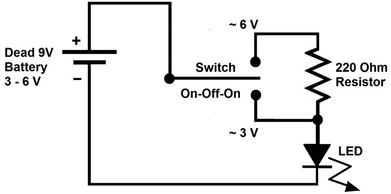
SCHEMATIC 1. Dead 9V battery flashlight.
Photo 1 shows the simple circuit using the on-off-on switch to either use the resistor or not use it, depending on the voltage the battery can maintain while driving the LED.
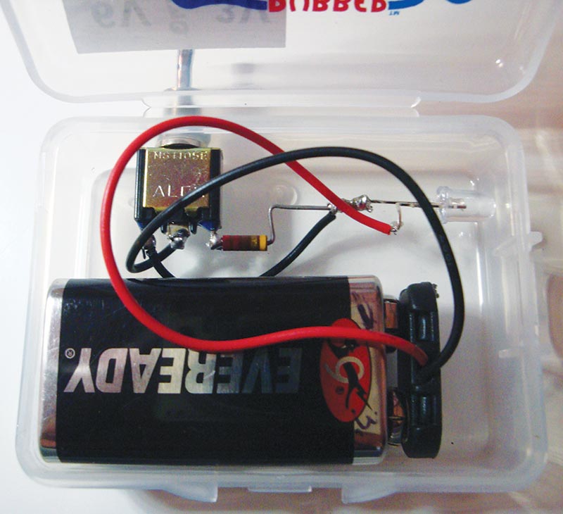
PHOTO 1. Dead 9V battery flashlight.
It’s not easy to tell if the 9V battery is weak enough to drive the LED directly, so the safest way to tell is to use a voltmeter, or to wait until the LED is obviously getting dimmer and try it without the resistor.
After I built this circuit, I came up with a much simpler way to attach the resistor. In my new approach, the resistor is soldered to the two ON sections of the on-off-on switch, and then one wire from one of those ends is connected to the cathode of the LED. This reduces the amount of wire needed. I hope you enjoy building this circuit. Now, you can use those dead 9V batteries as small flashlights or even as personal nightlights.
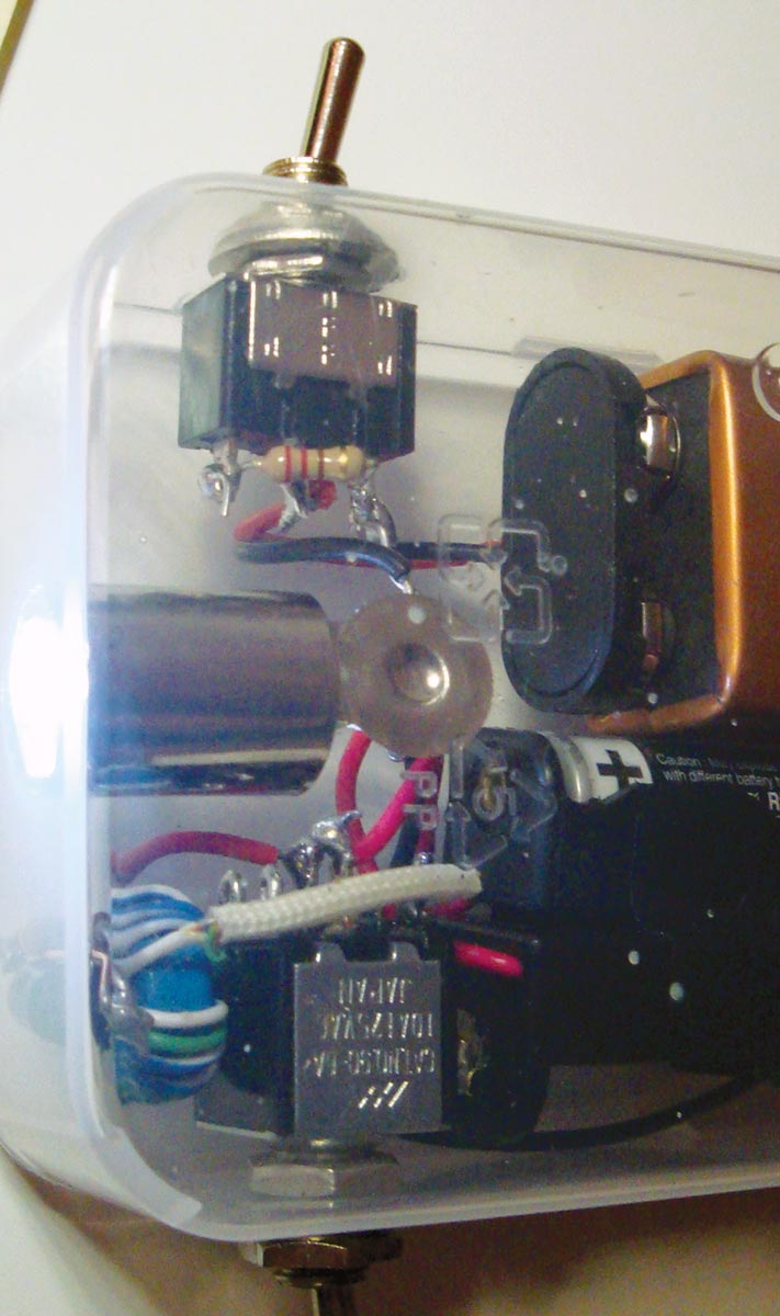
PHOTO 2. Close-up of resistor attached to the switch.
The Simple Joule Thief Night Light as a Soldering Island Project
My use of the term “soldering islands” here is similar to the Manhattan style of circuit building. One can do searches online to find articles on this construction technique. A good one I’ve come across is by K7QO. Manhattan Style construction uses small islands for solder points. These are usually cut from double-sided copper-clad circuit boards. The bottom side is then soldered to another single-sided copper-clad board and positioned to follow the circuit; either to make it easy for the signal, easy to construct, or both. The top side of each little island is then used to connect various leads. These islands can be either round or rectangular.
The difference between Manhattan style construction and these soldering islands is that there is no way to connect the soldering islands to a copper-clad circuit board without shorting out the entire circuit. These islands must either be glued to something — another board or the bottom or side of a box, for example — or float with enough room between them that they will not short out.
Another method is to use very high-valued resistors — 1 MΩ or more — to keep all the solder islands at a good distance from each other. When using these with a joule thief circuit, we have the stiff resistor, LED, and transistor leads to help maintain the distance between the solder islands.
I use this island method because there are times when I need to connect more than just two wires or leads together. I find that a small solder island makes this very easy to do. Using only the wires or leads is far more frustrating because the lead or wire never wants to stay in the position I need long enough for me to solder it to the other leads. Or, as I warm up the other two or more leads already soldered together, one of them pops off and I have to fight with all the leads to get them back together.
Other than using a soldering island, the only other method I’ve used is to tie them all with another piece of wire. Then, of course, as soon as I do that, I realize I need to connect another lead or two to the tied and soldered bunch of leads.
The material I’ve found that works really well is something we all throw away or recycle. This past week, I noticed that my wife had recycled a plastic wrap box (Photo 3).
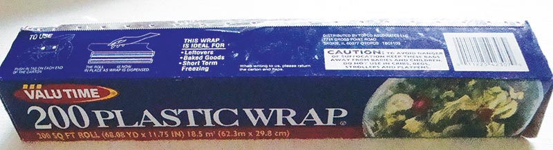
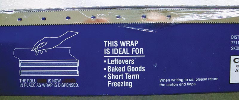
PHOTO 3. The plastic wrap box.
It wasn’t very flat, so I removed it to take it apart and flatten it. I noticed that the metal cutting edge was still attached to the box so I removed it to place it into a different recycling bag.
In looking at it, I wondered if I could solder something to it. So, instead of recycling the cutting strip, I tested it and found that soldering to it worked very well. I decided to make a night light out of a joule thief circuit using two small pieces of this material as soldering islands.
These islands made soldering multiple wires to the same point very easy, even though they were not attached to a board. Also, while the ends of this material are sharp, I find that pre-tinning them removes those sharp edges. Plus, it makes a nice island of solder that can be reheated to melt only a section of the whole island, thus making it very easy to add wires or leads.
Photo 4 shows two soldering islands cut from the plastic wrap cutting strip.
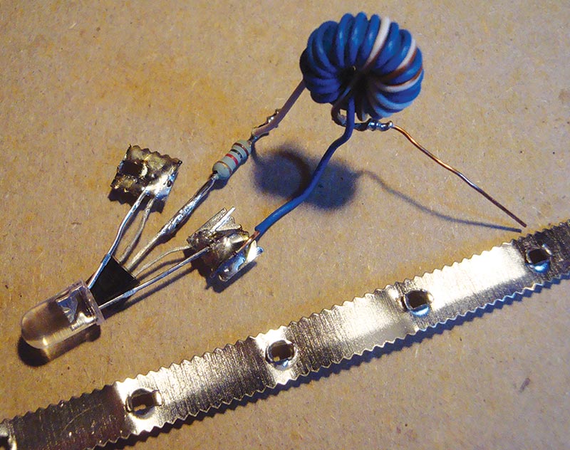
PHOTO 4. The solder islands’ joule thief.
This project didn’t really need these soldering islands since only two leads and one piece of wire from the inductor are the most connected together. However, it did make soldering them together much easier than getting the leads of the transistor and LED lined up and then tied together by the inductor wire and soldered together.
The inductor was then bent back to be above the transistor and LED before installing it in the small plastic box. Positioning the parts as well as the entire circuit was not critical either in relation to each other or in the box.
I completed this project with a small switch and two battery clips: one for an AA battery and the other for an AAA battery in parallel so that either size battery could be used without needing a converter case for the AAA battery to resize it to a AA battery.
A small amount of “liquid tape” was used to keep the battery clips and the circuit from moving around. The liquid tape can be removed if needed to service the circuit in the future, and it’s strong enough to hold up to normal use.
Photo 5 shows the finished joule thief night light in a box with the soldering islands hidden under the inductor.
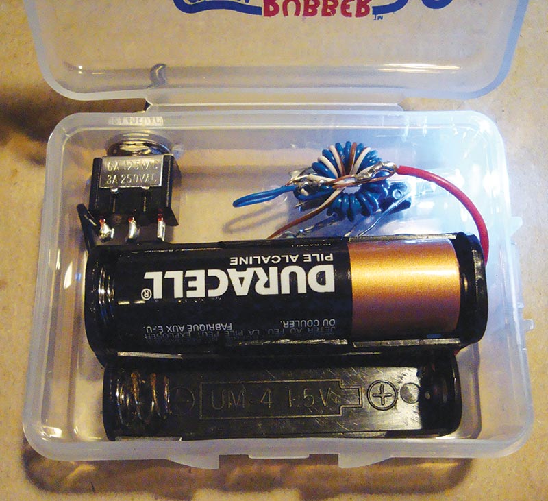
PHOTO 5. Joule thief in box with solder islands hidden.
Photo 6 shows the bottom of the box with the soldering islands visible.
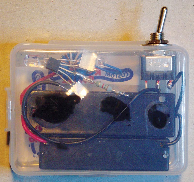
PHOTO 6. Joule thief night light with soldering islands visible.
Combining the Dead Battery 9V Flashlight and Joule Thief Night Light
This project is simply combining the previous two projects into one box and making it work with the same LED. There are many ways to do this. I built two in order to test out some part-saving ideas.
Generally speaking, the more parts we try to save, the more complex a circuit becomes. This was definitely the case with this combined project. It’s no longer super simple, but it’s not all that difficult either.
I’ll explain a bit first, and then show the photos of the two different approaches. I’ll include the schematic as well.
The first circuit used two switches: an on-off-on single pole switch for the 9V dead battery side of the project; and a double-pole-double-throw (DPDT) switch for the two AAA and AA battery holders. This powers the joule thief circuit and also disconnects the 9V battery section to the off joule thief circuit. In this circuit, the two battery holders are connected together in parallel so only one battery at a time can be in a holder; refer to Photo 7.
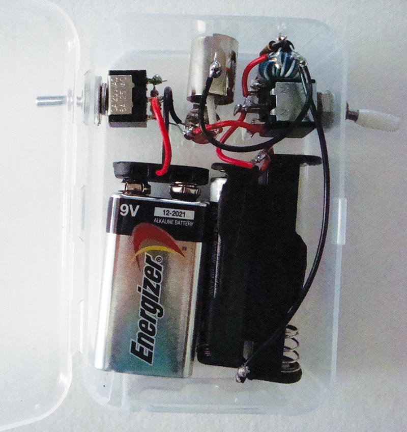
PHOTO 7. Dead battery 9V + joule thief night light with DPDT switch.
In the second circuit, I used two LEDs to separate the 9V battery from the joule thief circuit. This was necessary because I removed the DPDT switch and replaced it with a second on-off-on switch. This meant there was no way to separate the 9V from the joule thief circuit via the common positive lead of the LED. By adding a second LED in series with the first LED, this LED could be used as a blocking diode, restricting the current path from the 9V battery to the joule thief circuit.
The joule thief circuit is now connected to the second LED in the series and so it drives both LEDs. This means that the joule thief circuit had to boost the voltage to ~ 6V to turn on both LEDs in series. The only reason the joule thief stops at 3V is because that’s when the LED turns on and stops the voltage increase of the oscillator. So, the oscillator boosts the voltage to what is needed to turn on both LEDs.
By removing the more complex and expensive switch, I had to add the blocking diode. I figured I’d use another LED to do the blocking since I could then get light out of it as well. This saved the expense of the DPDT switch but added a minor cost for the second LED. This saved a little money probably at the expense of a shorter battery life.
You’ll also notice that I removed the AAA battery holder. This was because I found that the AAA battery will work in a double-A battery holder. It’s not as secure, but as a night light it doesn’t need to be. As a flashlight for children, I’d keep the AAA battery holder.
With an on-off-on switch, I found another way to hook up the double- and triple-A holders. Use the center connector of the switch for the output to the joule thief circuit, and then each battery holder could attach to the switch on either side and could be selected to supply power separately.
In this way, all three batteries could be installed. As one starts to get too dim, the weak battery could be turned off and then one of the other batteries could be switched in. Check out Photo 8.
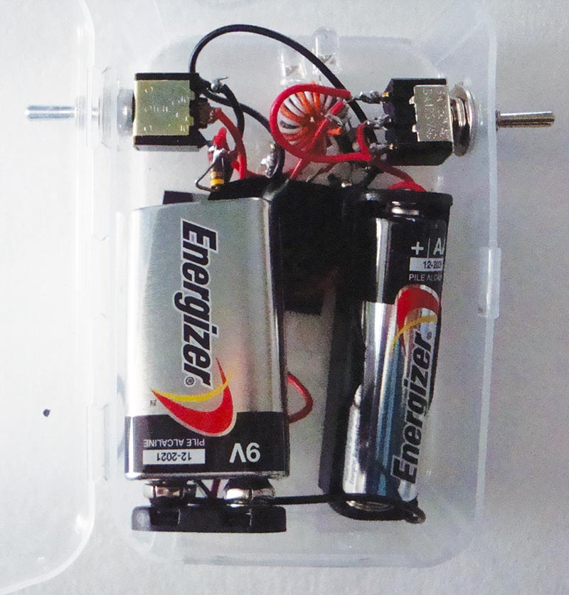
PHOTO 8. Using two LEDs to separate the two power sources.
Schematic 2 shows the two LED AA and AAA battery section with the power lead-in for the dead 9V battery. Take the power to the LED there and feed it in between the two LEDs as shown.
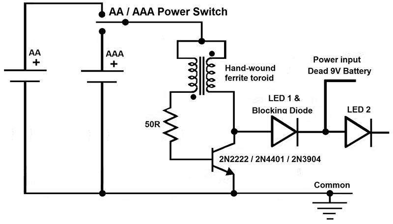
SCHEMATIC 2. Two LED version of the dead 9V/dead AA/AAA battery nightlight.
In the oscilloscope trace in Screenshots 1 and 2, we can see that the voltage for the two LED joule thief circuit goes up to almost 6.5V with a battery at 1.1V. It goes to 5.84V when the battery gets down to 0.6V.
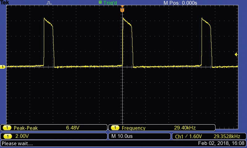
SCREENSHOT 1. Two LED trace battery 1.1V.
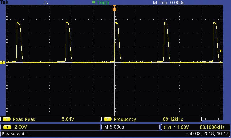
SCREENSHOT 2. Two LED trace battery 0.6V.
So, there you have it. Some fun simple circuits to light up your life. NV