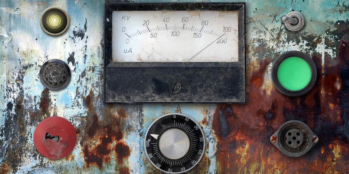
In this ever-advancing digital world, there is still room for the venerable analog panel meter. The one that most of us are familiar with is the moving-coil galvanometer that was invented by Jacques-Arsene D’Arsonval, a French physicist who lived from 1851 to 1940.
Figure 1 shows a block diagram of a typical meter movement where a moving coil is deflected against a set of calibrated springs within the magnetic field of a permanent magnet when a current is applied to the coil. It should be noted that an analog meter is an electro-mechanical device and will display an average reading.
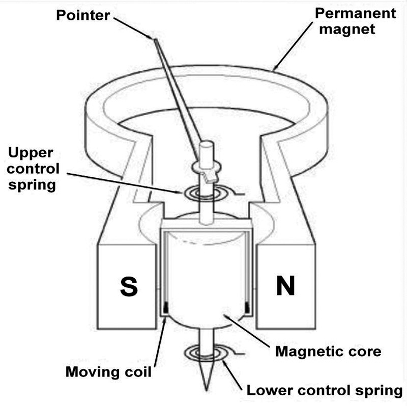
FIGURE 1. Meter movement.
Meters with the D’Arsonval movement all operate on current. The amount of electricity required for maximum deflection of the meter needle is called the full-scale current; this number can sometimes be found on the meter face in small letters. In Figure 2, the full-scale current is shown as 500 microamperes (500 µA).
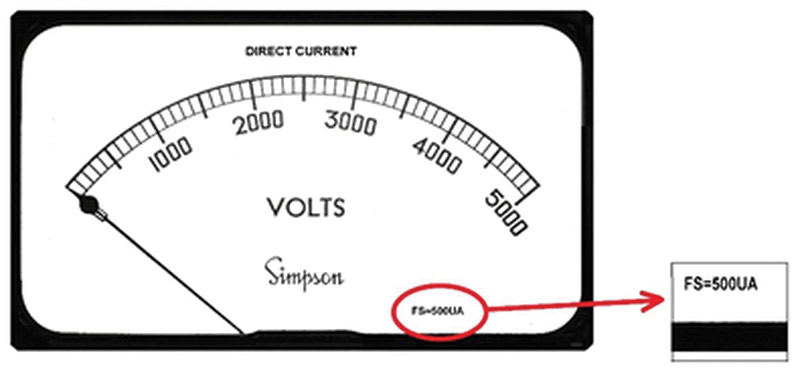
FIGURE 2.
Analog meters can be configured to measure almost any quantity: voltage, current, power, wind speed, humidity, temperature, altitude, barometric pressure, etc. Meters found in a surplus store or at a swap meet don’t necessarily show the scale under the needle that corresponds directly to the full-scale current. For instance, the meter scale might show 0-5,000 volts and the full-scale meter current might be 500 microamperes as in Figure 2.
In many cases, the full-scale current of the meter movement is not shown on the face. So, it is necessary to determine this first before the meter can be used in a circuit. The simplest way to do this is with a variable power supply, a decade resistance box (or 100K potentiometer), and a digital multimeter (DMM) with a very high input impedance of at least several megaohms. If a 100K potentiometer is used, then the multimeter should be able to accurately measure resistance to at least two decimal places.
Much greater accuracy can be obtained using a decade resistance box that is accurate to at least 1% since the resistance can be read directly from the settings:
- Before making any of the connections, set the decade resistance box to its maximum value to make sure that the full-scale current of the meter being tested is not exceeded, and turn the voltage adjustment on the power supply to its lowest level.
- Connect the power supply, resistance box, and meter as shown in Figure 3. The meter will have two connection posts at the back with the positive marked with a plus sign (+). Be sure to observe the polarity of the power supply and meter when making the connections. Failure to do this can result in damage to the meter.
- Set the power supply voltage to about +5 volts.
- Slowly decrease the amount of resistance in the decade box until the meter deflects exactly full-scale. Exceeding the full-scale reading may also damage the meter. Be careful not to decrease the resistance to less than 100 ohms.
- Measure the voltage across the decade box as accurately as possible.
- Measure the voltage across the meter movement.
- Disconnect the power supply from the meter circuit.
- Measure or record the resistance across the decade box or potentiometer.

FIGURE 3.
If the measured voltage across the meter is too low to obtain an accurate reading, then increase the power supply voltage to 20 volts while keeping the series resistance of the decade box to no less than 400 ohms to prevent damage.
If full meter deflection has been achieved, then all the information necessary to determine the full-scale current of the movement and to also calculate the meter internal resistance is now available.
If a DMM is unavailable to make an accurate voltage measurement, then inexpensive high-input impedance digital panel meters with millivolt accuracy are available on the Internet for about $5 as shown in Figure 4.
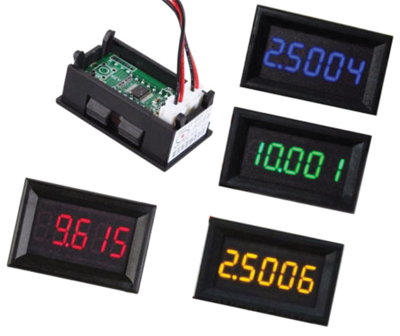
FIGURE 4. Digital panel meters.
Circuit current (I) = Resistor voltage (E) / Resistor resistance (R).
Meter full-scale current = Circuit current.
Meter internal resistance = Voltage across the meter / Circuit current.
There are two problems with the above approach when testing an unknown meter:
- The meter may have a built-in shunt across the movement internally in the case of a direct-reading ammeter. This is quite common in ammeters up to 10 amperes.
- The meter may have a built-in internal series resistor in the case of a direct-reading voltmeter. This is quite common in voltmeters up to a few hundred volts.
In the case of a direct-reading ammeter, the wattage rating of the decade resistance box could easily be exceeded. If we assume that the decade box or potentiometer is rated at 1/4 watt, then (in the worst case) with five volts applied to the circuit, the resistance should not be adjusted lower than 100 ohms to prevent damage to the resistor(s).
If the meter contains an internal shunt, then it may not fully deflect even with 100 ohms in series. If it is a direct-reading ammeter, then there will be close to 50 milliamperes flowing in the circuit without full deflection.
In the case of a direct-reading voltmeter, the meter will read very close to the applied power supply voltage when the resistance is adjusted down to our minimum of 100 ohms, and the voltage across the series resistor will be minimum. If the meter scale is showing a voltage range, it is probably reading correctly.
This can obviously be checked by comparing the power supply voltage with the reading on the meter when the series resistance is low. To make sure that it is not an ammeter, the voltage across the resistor should always be checked and the circuit current calculated.
Once the full-scale meter current and the meter internal resistance have been determined, then external resistance can be added in series to measure voltage or in parallel to measure current.
Full-scale meter values can vary widely. The lowest current (most sensitive meter) that I have has a full-scale range of 20 microamperes. The meter used in the Bird 43 wattmeter, for instance, has a full-scale deflection current of 30 microamperes.
The more sensitive a meter is, the more options it offers when designing it into a circuit. This will be demonstrated later.
Measuring Voltage
To configure a meter to measure voltage, a resistance is usually placed in series with it. If a meter has a full-scale reading of one milliampere, then the series resistance is calculated at 1,000 ohms per volt (minus the internal resistance). (One volt across a 1K ohm resistor equals one milliampere). For instance, if a full-scale voltage reading of 10 volts is required and the internal resistance of the meter is 50 ohms, then the series resistance equals:
10 x 1000 - 50 = 9950 ohms
For the same voltage range, if the meter has a full-scale reading of 50 microamperes, then the series resistance is calculated at 20K ohms per volt (one volt across a 20K ohm resistor equals 50 microamperes). If the internal resistance is 2,500 ohms, then the series resistance equals:
10 x 20K - 2500 = 197,500 ohms
When higher voltage ranges are required — especially when greater than a few hundred volts — it is always a good idea to place the series resistor on the higher voltage side of the meter and connect the opposite terminal to ground as shown in Figure 5.
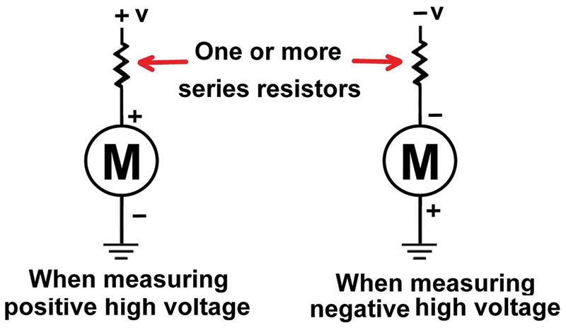
FIGURE 5.
At voltages greater than 250 volts, then more than one resistor should be used in series — especially if the resistors are rated at 1/4 watt since this is their maximum recommended continuous voltage rating.
A better solution is to use a voltage divider network with the meter connected across an additional small-value series resistor connected to ground (Figure 6).
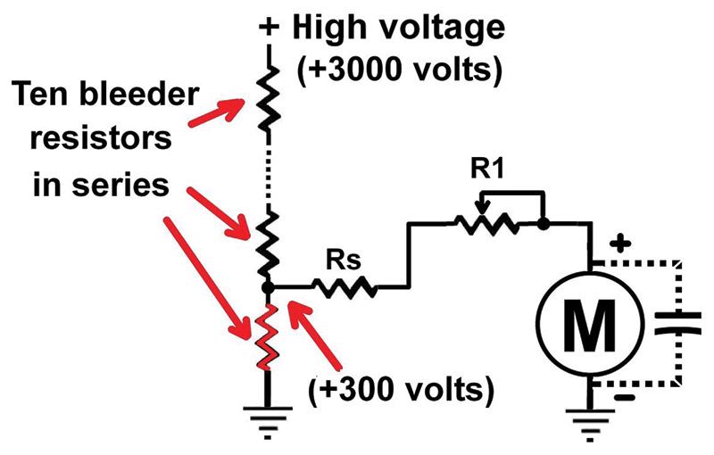
FIGURE 6.
Obviously, this can only be done if the voltage source can tolerate the additional current load.
It is also important not to exceed the wattage rating of the series resistor. As an example, if a one milliampere movement is being used and the meter range of 300 volts is desired, then the series resistance would be approximately 300K ohms. If a single resistor is used to drop the voltage to the meter, a resistor of at least 300 milliwatts is required.
This would exceed both the voltage rating and the wattage rating of a 1/4 watt resistor.
Most high voltage power supplies used in tube-type amplifiers have a built-in bleeder-resistor network consisting of one or several high wattage resistors. This network is used to discharge the high voltage capacitor bank when the amplifier is turned off to prevent possible electrocution when the covers are removed.
The resistance value of the bleeder-resistor network is usually a compromise between the amount of time that is required to completely discharge the high voltage capacitor (at least five time constants, typically 30 seconds) and the power draw of the bleeder-resistor given off as heat when the amplifier is in operation.
The meter shown in Figure 6 can be configured to accurately measure the high voltage without subjecting the meter to what could be a lethal potential. The meter is connected (through a series resistor) at the bottom resistor in the chain. If the voltage across the bottom resistor is greater than a few hundred volts, then an additional small-value resistor can be placed in series at the ground side of the network to limit this to some reasonable level.
As an example: If the voltage to be measured is 3,000 volts and the high voltage filter capacitance is 30 microfarads, the bleeder-resistor should discharge the power supply to near zero in five time constants:
One time constant 5 x TC = R x C, then R = 5 x TC / C.
R = 30 / 30 x 10E - 6 = 1,000,000 (one megaohm).
If the bleeder-resistor network consists of 10 x 100K resistors to make up the required one megaohm total, then the bottom resistor will have 300 volts across it during operation.
The dropping resistor (Rs) in series with the meter (added to the meter series resistance) is now in parallel with the bottom resistor in the chain and — depending on the sensitivity of the meter — these must be taken into account if an accurate voltage reading is to be realized. This problem can be mitigated by reducing the value of series resistance (Rs) and adding a series potentiometer (R1) to adjust for the correct voltage reading.
In this example, the meter is actually reading 300 volts, which represents one tenth of the actual voltage being measured. The scale on the meter face could show a voltage range of 0 to 5,000 volts, and R1 would then be set to a 3,000 volt deflection which would be 3/5 of full scale.
Measuring Current
To configure a meter to measure current, a resistance (called a shunt) is placed in parallel with it. Full-scale current measurements ranging from microamperes to tens of thousands of amperes are possible depending on the full-scale current range of the meter.
For higher current measurements, three shunt standard full-scale measurements are typically used: 50, 75, and 100 millivolts. The current and millivolt rating of the shunt is usually marked on the side of the connection posts.
The meter being used in parallel must be sensitive enough to accommodate the millivolt range of the shunt. Many panel meters are already designed to connect directly to the shunt, and the full-scale of the meter in millivolts is often shown in small letters on the meter face. Refer to Figure 7.
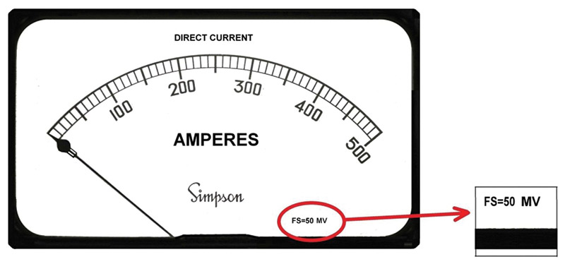
FIGURE 7. A 500 amp scale.
The scale on the meter face is then scaled to conform to the shunt current rating. A meter with a five milliampere full-scale reading and an internal resistance of 10 ohms will have a full-scale rating of 50 millivolts. Likewise, a meter with a one milliampere full-scale reading and an internal resistance of 50 ohms will also have a full-scale rating of 50 millivolts.
For high currents, the resistance of the shunt will be so much lower than the internal resistance of the meter (in parallel) that the actual current measurement is affected very little.
High current shunts quite often have one or more parallel flat pieces of copper or brass in parallel between the connecting posts as shown in Figure 8.
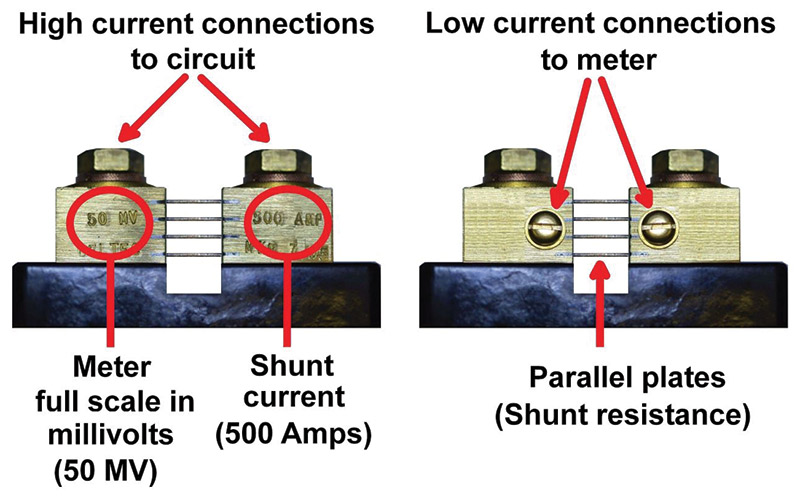
FIGURE 8.
The width and thickness of the flat pieces determine the resistance and hence the current rating.
Several flat pieces are used in parallel to prevent the shunt from heating due to the high current, as heating will increase the resistance and distort the meter reading. Used shunts will sometimes have one or more small notches in the side of one or more of the flat pieces.
These cuts or notches are usually made at the factory, slightly increasing the parallel resistance of the shunt to accurately adjust the meter reading. The full-scale range of any meter that is sensitive enough can be adjusted to the correct millivolt range required by the shunt.
For instance, a meter will a full-scale current rating of 50 microamperes and an internal resistance of 600 ohms can be adjusted to 50 millivolts full-scale by adding the right amount of series resistance.
As an example, if the shunt is rated at 100 amperes and has a parallel voltage of 50 millivolts, then the resistance in series with the meter that is across the shunt is calculated as:
(0.05 volts divided by 0.000050 amperes) = 1000 ohms minus the 600 ohms meter internal resistance = 400 ohms.
A “Kelvin” configuration (shunt) resistor features four leads rather than just the two connection points shown in Figure 8. These four terminal resistors enable a current to be applied through two opposite leads and a sensing voltage to be measured across the other two leads. The Kelvin configuration effectively eliminates the resistance and temperature coefficient of the leads.
A Kelvin connection is essential for accurate sensing. Current measurement using a shunt resistor and voltmeter is particularly well-suited for applications involving particularly large magnitudes of current. Refer to Figure 9.
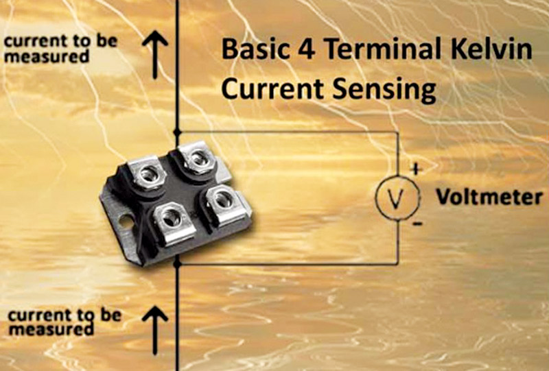
FIGURE 9. Kelvin current.
In such applications, the shunt resistor’s resistance will be in the order of milliohms or micro-ohms, so that only a modest amount of voltage will be dropped at full current.
Resistance this low is comparable to wire connection resistance, which means voltage measured across such a shunt must be done in such a way as to avoid detecting voltage dropped across the current-carrying wire connections which may result in magnetically induced measurement errors.
When high voltage is involved, it is never a good idea to put the current meter on the high voltage side of the power supply. This could put thousands of volts inside the meter on a front panel and can be very dangerous — even lethal. Figure 10 shows the correct way to make the connection.
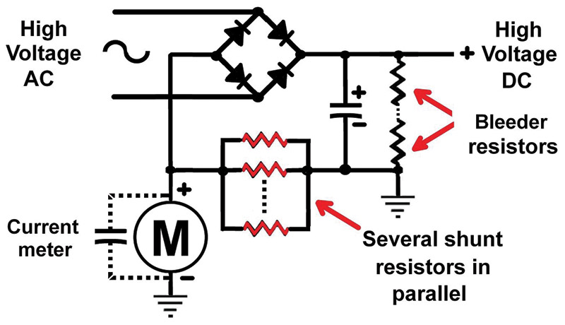
FIGURE 10.
When creating your own shunt out of individual resistors, make sure that they are several times oversized in wattage to prevent heating and also to prevent possible failure. Always use several resistors in parallel since one resistor could fail and open up putting the full high voltage on the panel meter.
If a full-scale meter reading of five amperes is required and the full-scale voltage across the shunt resistor is set to five volts, then a shunt resistance of one ohm is required with a wattage rating of at least five watts.
In this case, a good solution is to use ten 10 ohm/one watt resistors in parallel to produce the one ohm resistance required. The meter is actually reading zero to five volts, but the scale on the meter would read zero to five amperes as each volt of deflection represents one ampere.
One slight disadvantage when using this method to measure the anode current of a tetrode or pentode vacuum tube in a power amplifier is that the measurement will show the combined currents of the anode and the screen grid since the measurement is being made on the cathode side of the circuit.
Volt-Ohm-Milliammeter
Measuring current, voltage, and resistance are combined in an analog volt-ohm-milliammeter (VOM). An example from the 1970s is the RadioShack Micronta model shown in Figure 11. Several ranges of DC and AC voltages and currents are selectable by a multi-position switch.
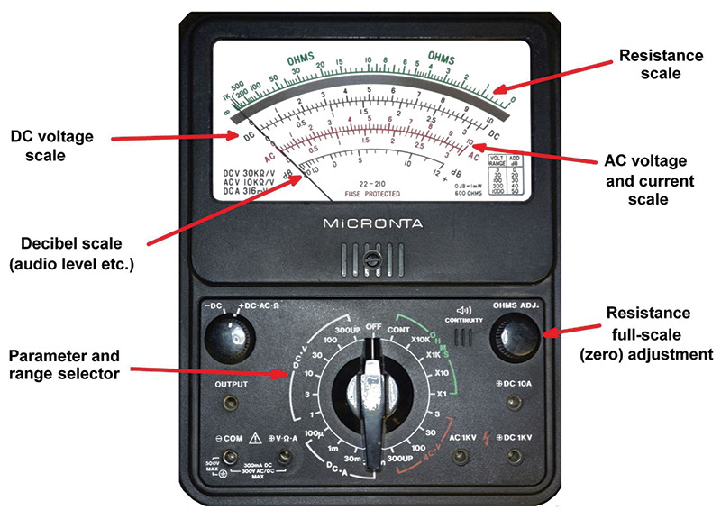
FIGURE 11. Multimeter (VOM).
Resistance is measured by first shorting the two test leads and adjusting the needle to a full-scale reading, which represents zero resistance. This is done to adjust out the resistance of the test leads and is especially important when measuring low resistor values. Notice that the resistance scale is not linear. The VOM contains an internal battery (usually nine volts) which supplies the necessary current when measuring resistance.
Non-linear and Other Measurements
As mentioned above, a meter can be configured to measure almost any quantity if a suitable sensor is available or can be constructed. The sensor required to make the measurement on the meter in Figure 12 might prove to be difficult, however.
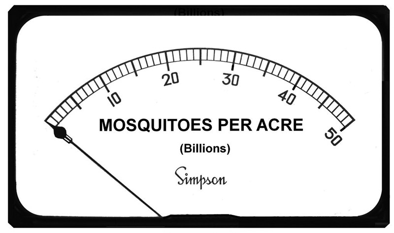
FIGURE 12. Mosquito meter.
The Texas Instrument’s LM35 is a precision temperature sensor that produces an output voltage linearly proportional to the Centigrade temperature, with an accuracy of ±1/4°C at room temperature and ±3/4°C over a full range of -55°C to 150°C. This device has a low output impedance capable of driving a correctly calibrated analog panel meter directly. Similar devices are available for measuring temperature in Fahrenheit.
There are literally hundreds of sensors for detecting and producing a voltage from almost any measurable parameter.
Additional Notes
Analog meters in high frequency amplifiers should always be shielded from the RF (Radio Frequency) energy and bypassed with a 0.001 microfarad (1,000 picofarad) capacitor with the necessary voltage rating (refer back to Figures 6 and 9). Most amplifier circuits use 1,000 volt bypass capacitors even though the DC voltage across them might be quite a bit lower. The higher voltage rating is necessary to ensure that the capacitors have sufficient internal area to handle the RF current.
Some meters have what is called a mirrored scale as shown in Figure 13.
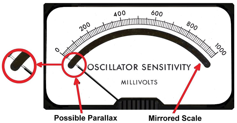
FIGURE 13. Meter with mirrored scale.
The needle in the meter movement functions as the pointer to the measurement on the scale and is always at some small distance from it. When viewed from different side angles, the needle is not directly over the scale. This can result in slightly different readings due to parallax.
The mirror is typically right under the scale and reflects the position of the needle more accurately, thus minimizing the parallax problem. When reading the meter, just line up the scale with the reflection of the needle in the mirror.
Analog meters with very small (microampere) full-scale currents should always be handled and stored with a short across the terminals when not in a circuit to prevent damage to the movement. This will dampen any movement of the needle since the coil within the magnetic field can act as a generator when the meter is jarred suddenly.
If a meter is not sensitive enough to measure very low currents, an operational amplifier (op-amp) with a very high input impedance can be used to amplify the current so that it can be measured. The Texas Instruments’ OPA129 has a Difet input bias current of 100 femtoamperes (1E-13) and can boost very low currents to the point where they can be displayed on an analog meter. An interesting approach can be viewed at https://www.youtube.com/watch?v=xbKiAl2ioBg.
Customizing the Meter Scale
There are several ways of making a custom scale. Years ago, I wrote a program in the Hewlett-Packard Printer Control Language (PCL) to produce various meter scales. I have also produced scales using Microsoft Paint. The process using both of these methods was tedious. Today, however, there is a much better “Meter” program available on the Internet from www.tonnesoftware.com.
One of the advantages of an analog meter is when measuring a parameter that is changing fairly rapidly in real time — as in the measurement of plate current in a high frequency amplifier that is being modulated with voice in Single Sideband (SSB) or Morse code (CW).
The analog meter gives an immediate (average) indication of the change in current where an abnormal reading can indicate a problem. An attempt to duplicate this effect has been used in some of the RF linear amplifiers made by Alpha and others using a string of Light Emitting Diodes (LEDs), but there is something magical about watching the analog meter in real time.
Where to Purchase Sensitive Analog Meters
Manufacturers of analog panel meters are becoming quite scarce, but new meters are still available online. The panel meter shown in Figure 14 has a full-scale reading of 50 microamperes and can be configured to measure most parameters. They are available from China for about $7 (and they pay the shipping!). I currently have several of these meters in various circuits and they work great!
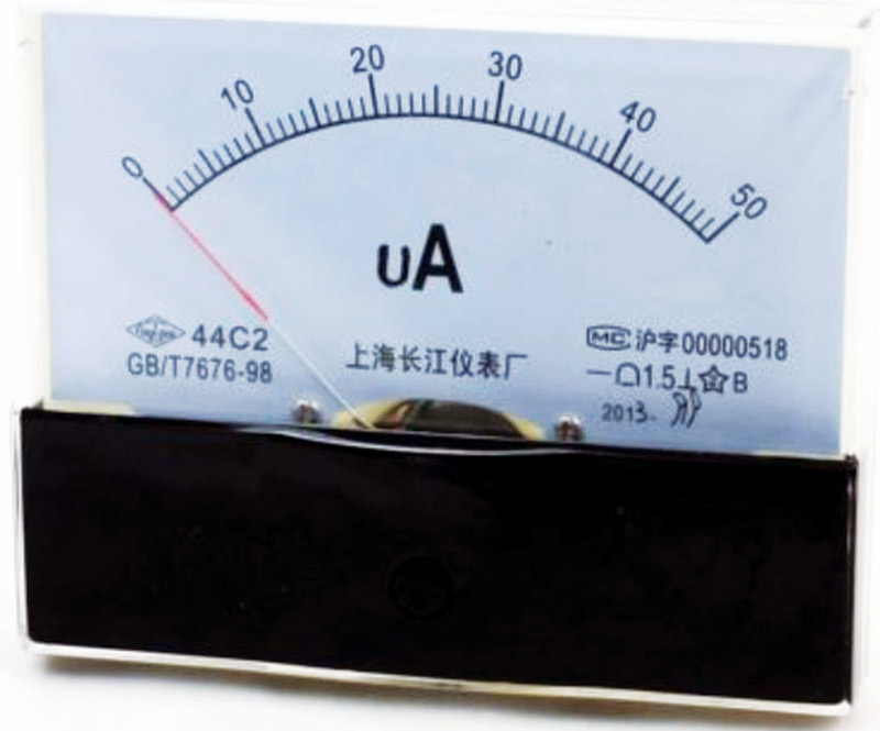
FIGURE 14. A 50 microampere panel meter.
Conclusion
One of the classes I took in my first year of college in the early 1960s was taught by a retired Navy man on the various types, configurations, and uses of analog meters. (I don’t think any such class exists today). At the time, thousands of meters with many different sizes and scales were available for sale in the electronic surplus stores on Market Street in San Francisco, CA from equipment still being decommissioned after World War 2.
Most meters could be bought for one or two dollars. This was a memorable time for us hobbyists and ham-radio types. We put meters on everything just so the equipment would look impressive in a 19” rack. (They were cheap, so why not!)
Using an analog meter to make any measurement is only limited by one’s imagination. Plus, it’s fun to think up new uses for them. A measurement can be esoteric enough that it might take the casual observer some time to figure out what they are looking at. How about measuring the height of an antenna on a motorized tower in Femto-Light-Years (FLYs); see Figure 15. (Nah! That might be a bit too weird!)
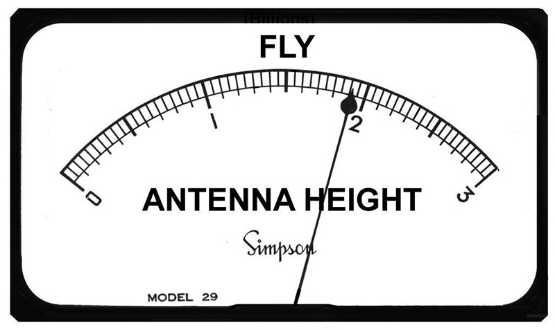
FIGURE 15. A reading of 1.9 FLY = a height of 58.9 feet.
Femto = 10E - 15.
One light year = 5,869,713,600,000 miles
A FLY turns out to be almost exactly 31 feet! Happy (analog) metering! NV