Like many “Tom Swift” type readers of N&V, over time (at least 70 of my 81 years so far), I’ve accumulated great quantities of “junque.” I still maintain a retirement business (Diacad Associates, Rumney, NH)) designing, assembling, repairing, and upgrading PC clones for local desktop computer users. However, it became time to downsize and clean up the shop.
Business became slow due partly to Covid and partly to the abandonment of desktops by many in favor of handhelds and laptops which are beyond my scope. This has been a good time to get my shop in order. Over the past few years, I have taken 10 Tundra truckloads of electronic and mechanical scrap to an ethical recycling center, and my 3,000 sq ft shop hardly looks any different. Some stuff — while useless to the business — is difficult to part with.
With time on my hands, I opted to play with the material in purgatory: too good to toss, not useful to business. I have occasionally made chaotic neon light boxes using relaxation oscillator techniques as gifts, and in the 1970s sold them on consignment in Harvard Square boutiques. They ran on batteries or 120V AC; usually NE-2s in small plastic cases or Nixie tubes under glass domes. I still assemble them sometimes; a few are designed to make strange sounds with chaotic light patterns (Figure 1).
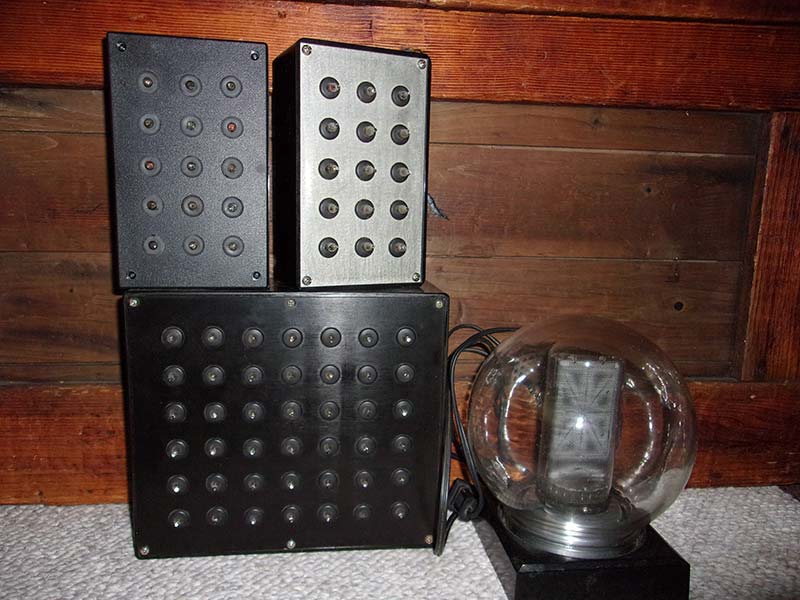
Figure 1 – Chaotic NE-2 and Nixie tube projects.
Chaos takes many forms. (See “Chaos” by James Gleick, a very readable overview.) The chaos I employ are “race conditions” — normally a great nuisance in the working day of the electrical world but used here for its surprising and amusing artistic appeal. Race conditions can happen when parallel repetitive unsynchronized (but linked) processes occur within a system; the timing is thrown off by slight electrical or mechanical differences from process to process. Real components differ from ideal specifications.
I decided to make the “Chaostron:” a giant version of my past chaotic creations, using a few innovative approaches with my inventory of relays, light bulbs, and defective PC power supplies — often the culprit in a dead computer. I have a number of these, as anyone who fixes desktops does.
The relays on hand were 120V AC with three sets of contacts: NC/NO, NC, and NO (NC = normally closed, NO = normally open). A 120V AC relay will ordinarily pull in on less than 120V DC and be the basis for a relaxation oscillator similar to neon boxes. To complete the relay oscillator, I had some power resistors similar to DC resistance of the relay coils, which was about 1500 ohms.
The applied voltage to the resistor would be 150V DC from rectified and filtered line voltage. The capacitor would be connected parallel to the relay coil. With these values, the capacitor would charge up until the relay pulled in (at about 60 volts), providing a relaxation oscillator. The oscillation would be designed for just under a second — ideal for flashing the Chaostron lights (Figures 2 and 3).
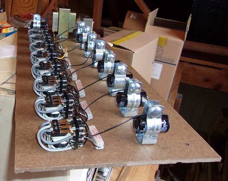
Figure 2 – Relay board.

Figure 3 – Relay circuits: two types for horizontal and vertical.
A computer power supply ordinarily has two large 200V electrolytic capacitors at their input, from about 300 µF to over 800 µF. I have found that these are usually okay in defective units, as well as the input circuit diodes; generally, four in a bridge. These would be critical parts for the Chaostron.
Capacitors this large can be expensive if purchased instead of scrounged from old power supplies. There are many other parts in the power supply, and the failures are almost always somewhere else.
The capacitors will endure because they would be operating at much lower than their voltage rating, and any difference in their capacities will aid in the chaos effect as any differences in the relays or resistors themselves — this is an anti-precision project!
If you do something like this, the capacitor and resistor values will depend on the DC resistance and closing voltage of the relays, so it will require some experimentation to get the desired effect. By the way, the power supply cases themselves are also useful for many other projects, including the “peripherals” to the Chaostron to be described later.
Lights are standard incandescent 40W bulbs from a stash of a hundred picked up for 19 cents each at a closeout years ago. I had put them aside because they were shortly obsoleted by CFLs and much later by LEDs. However, their quick on-off timing is ideal for the Chaostron circuitry, which would be a 3x5 matrix.
The 15 bulbs are each connected to a diode and fed by the five “horizontal” relays with the hot side of the 120V and grounded on the cold side by the three “vertical” relays. The surplus light sockets on hand were porcelain making the Chaostron too heavy, so I quickly purchased plastic ones instead. The bulbs are thus fed by the equivalent of about 70 volts and should last longer than rated.
Also, I added circuitry with more diodes to apply less than 24 volts to the bulbs as a constant minimum, keeping the bulb filaments warm to minimize thermal shock when being switched on and off.
I used the NC contacts on the relays to feed the lights, so when power to the relays was cut, the lights would all come on. This feature was to test whether any of the bulbs needed replacing (Figure 4).
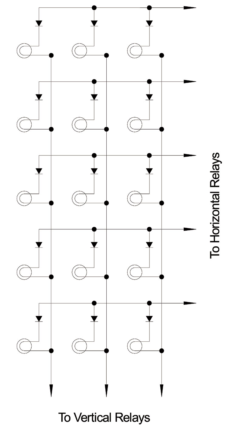
Figure 4 – The 15 light matrix.
I used the extra set of NO contacts on the eight relays to switch 120V AC to eight sockets for optional “peripherals” — external 120V AC gadgets like noisemakers to add to the fun if desired.
Since some may be partially inductive loads, snubbers protect relay contacts from arcing; 180V 5W Zener diodes are connected in full-wave diode bridges, so the Zeners would see and stop DC spikes (Figure 5).
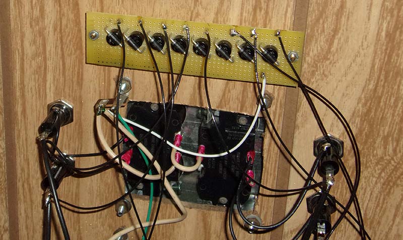
Figure 5 – Eight snubbers wired to eight outlets for peripherals.
The peripherals were comprised of whatever I had laying around (with some additional circuitry) that could make a noise or other disturbance, ran on 120V AC, and would fit into an empty PC power supply metal box.
This included loudspeakers with simple oscillators, an alarm bell, fans with plastic rubbers to make noise against the blades, small motors that would tumble balls — even a discarded Oster massage unit.
This latter would cause the box to jump and try to “walk” away from the Chaostron, provoking laughter from onlookers. When all eight of the peripherals were hooked up and running, the racket was almost deafening (Figure 6).
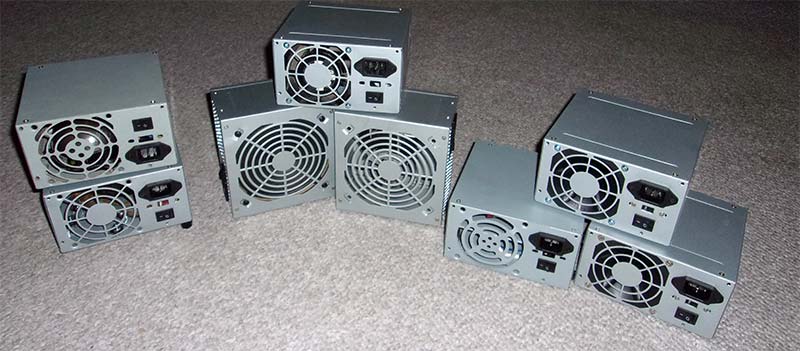
Figure 6 – “Peripherals:” noisemakers inside old power supply cases.
For the chassis, I used old office shelving cut down to the Chaostron dimensions (12”x30”x45”). Paneling was scraps of hardboard wall panel with the pattern turned inward; very easy to work with and pleasing in appearance.
For visibility and to see the relays working, the back is an acrylic sheet to protect the circuitry from curious viewers and to protect viewers from the circuit voltages (Figure 7 and Figure 8).

Figure 7 – Back view – taken before wiring.
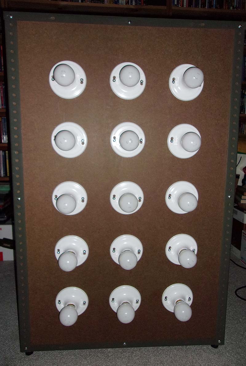
Figure 8 – Completed Chaostron.
You can see the Chaostron in action in a .mov video made shortly after its construction (in the Diacad Building attic); it’s in the download zip for this article.
As a final note (refer to Figure 9), since we’re dealing with 120V AC in this project, I used IEC 3-wire AC power cords, so all exposed metals on the Chaostron and its peripherals are thus grounded.
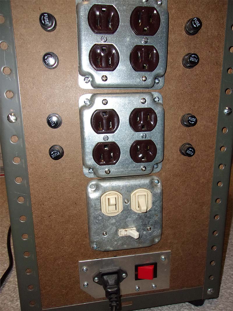
Figure 9 – Side panel with peripheral outlets, fuses, and control switches.
All 120V AC circuits are properly fused. Safety does take priority over chaos! NV
Downloads
What’s In The Zip?
.mov File of CHAOSTRON in action.