Stop spending hours fighting your breadboard! With the Dr. Duino Explorer, you’ll save a ton of time on your next Arduino project.
It happens to the best of us. You get your Arduino sketch done. You start wiring up your hardware on a breadboard or your shield. Next, you upload and run your sketch, and low and behold, nothing works. It’s hard to tell at this point whether it’s a software or hardware issue. After much troubleshooting, you discover that you have a bad jumper wire. Or, perhaps you soldered a wire to the wrong pin. Or, your temperature sensor has SDA and SCL reversed. The list is endless.
Meet the Explorer
The new Dr. Duino Explorer board takes aim at both novice and experienced Arduino users. If you’re a beginner, the Explorer is a complete learning tool with built-in sensors and ready-to-go programs. It even comes with an Arduino Nano, so there’s nothing else to buy. However, for those of us with many Arduino projects under our belts, it’s worth a hard look as a great hardware development and troubleshooting rig.
The board contains an array of commonly used sensors and modules with the ability to connect and disconnect what you need at will. It has a novel mechanism for routing digital and analog I/O pins to wherever you need them.
Figure 1 shows a top-down view of the Explorer.
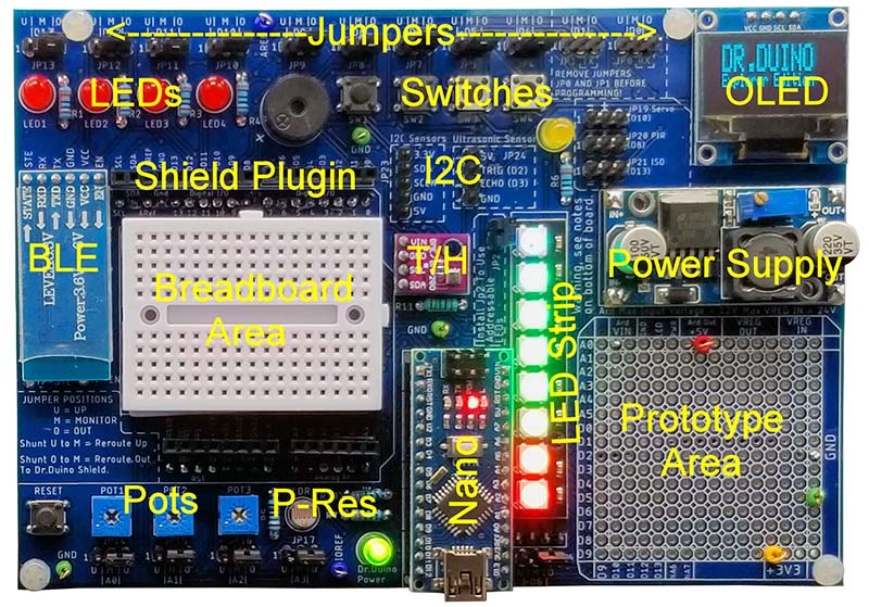
FIGURE 1. Dr. Duino Explorer board top-down view, showing major components.
There are general-purpose LEDs, switches, and potentiometers that can be used for either troubleshooting or to test your sketch on the breadboard. In addition, popular sensors and modules are installed that will likely be used in many of your projects.
Here’s a rundown of each component on the board:
- Four general-purpose LEDs. A set of four red LEDS with 330 ohm current-limiting resistors that are tied to I/O pins D10 through D12.
- Four pushbutton switches. These are micro-switches tied to I/O pins D4 through D8, with the other switch contact tied to ground. There are no pull-up resistors, so be sure and use the PULLUP option when defining these inputs with the pinMode() function.
- Three 10K potentiometers. These 10K ohm pots are tied to analog I/O pins A0, A1, and A2. You can read their values as a 0-1023 number using the analogRead( ) function.
- One photoresistor. This is a light sensitive resistor also called an LDR (Light Dependent Resistor) that is tied to analog I/O pin A3. By varying the amount of light, the resistance changes dramatically from a few megaohms in total darkness to a 100 ohms or so in bright light. The analogRead() function will return a value based on the brightness of the light striking the surface.
- 128x64 OLED display. If you’re used to those ancient 16x2 LCD backlit displays, this monochrome blue OLED will be a breath of fresh air. It’s based on the popular SSD1306 chip, where there are many Arduino libraries available to display text in various sizes, fonts, as well as images.
- BLE Bluetooth module. This module is the newer (Bluetooth Low Energy) type that supports communications with both Android and iOS devices. It uses an asynchronous UART interface to send and receive data between the connected device and the Arduino. It’s connected to the hardware UART I/O pins (D0 and D1). These pins are also used to program your Arduino and for use by the serial monitor, so you’ll need to change jumpers after uploading your sketch to use this module.
- Piezo buzzer. This is a tiny piezoelectric speaker connected to I/O pin D9. It can be used to make tones and sounds by sending square waves to the I/O pin. Note that these types of devices typically have very low audio quality and are not suitable for music playback.
- 2812 LED strip. If you haven’t messed around with the 2812 addressable LED arrays yet, here’s your chance. Each LED contains a red, green, and blue LED that can be tweaked in software to create millions of colors that make for nice analog indicators or simply to create a light show. The LED array on the board has eight positions.
If you opt for the Expansion Pack, you’ll also get a servo, motion detector, MP3 player module, atmospheric sensor, and more Dupont-style jumper wires than you could possibly need.
The Explorer accepts either an Arduino Uno or Nano. The Uno actually plugs in on the bottom of the board, leaving the top side opened for plugging in your own custom shield or for use with the mini breadboard (Figure 2).
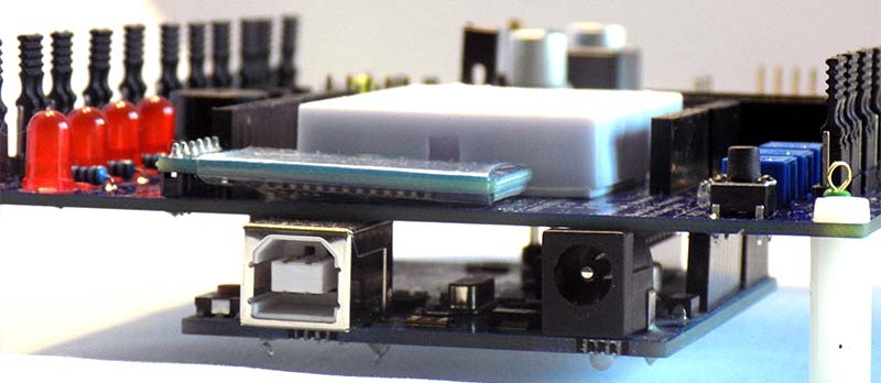
FIGURE 2. Arduino Uno mounts on the bottom for easy access to the breadboard area or an installed shield.
You can’t use both an Uno and Nano at the same time as there is only one set of hardware.
A Nano is included in the kit. This is a plus if you’re a beginner as there is nothing else to buy to get started. If you’re a seasoned Arduino user, it’s nice to have another Nano in your arsenal.
Some Assembly Required
The Explorer board comes as a kit. If you have some experience with a soldering iron, you shouldn’t have any problems putting it together. Most of the soldering involves installing the many headers for switching the hardware in and out.
Everything is through-hole (there’s no SMD devices) and all parts are on .1 inch (2.54 mm) centers.
You don’t get an assembly manual with the product. Instead, you go to a section of the Dr. Duino website for instructions. I usually prefer a hard copy of the assembly with kits like these. However, I was pleasantly surprised at the 50+ web pages that steps you through the assembly process with lots of photos and detailed instructions at every step. You get a picture of the component, a picture of where it goes on the board, and additional info such as solder it now, wait until later, as well as color code markings for each resistor.
The board comes with a generous supply of test points which are little soldered-in loops for your scope or multimeter probes. The test points are at voltage in/out points and several ground points all over the board. You won’t be searching for a place to connect your ground probe using this board.
It took me a little over an hour to fully assemble the board. I would guess most people would use anywhere from one to three hours, depending on your soldering experience. The good thing about building it yourself is that you learn about all the peripherals and components on the board as you go. And believe or not, this kit comes with some extra spare parts.
After the board is finished, you install the Dr. Duino library and run a testing sketch. The test sketch steps through the entire board interactively via the Arduino IDE (integrated development environment) serial monitor to make sure all the soldering is correct and everything works as it should.
All the parts come in a plastic case that doubles as an electronic enclosure. There are a handful of fully working projects included. Step-by-step details are provided in building these projects, including drilling and mounting instructions of the sensors to the case. While experienced users may not use this feature, it’s great for the beginner to create complete working projects without trying to modify sample code or search the Internet for help.
3A Power Supply
The board comes equipped with an adjustable three amp power supply. It’s a high efficiency step-down switcher (low heat generation) that will accept up to 24 volts input with a pot-adjustable output. Figure 3 shows the power supply module installed above the prototype area.
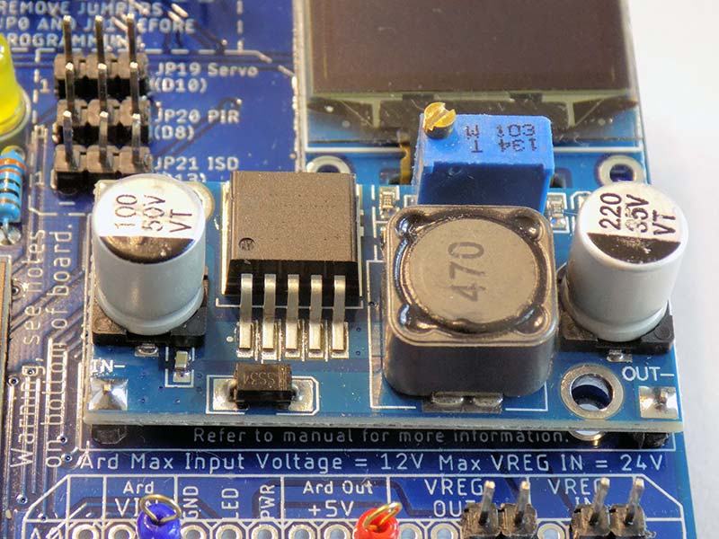
FIGURE 3. Three amp adjustable power supply. Up to 24 VDC input voltage with 3-20 DC output.
Aside from a power-on LED, this supply is not connected to anything on the board. It’s up to you to use it however you see fit. Perhaps you need a high current 5V or 12V supply to drive a motor, some servos, or a fan. The power supply inputs and outputs are routed to several holes in the prototype area.
Surrounding this area are pads that go to every Arduino digital and analog I/O pin, so it’s easy to build up say, a MOSFET or H-bridge driver or wherever you need a high voltage and/or high current power source.
Be careful though. The instructions caution to use a fuse with the power supply. A reverse power/ground connection on a component or a short circuit at three amps can do some serious damage to your circuit or the power supply itself.
Reroute It Technology
This is what the company calls its connect, disconnect, and rerouting system. It’s a simple concept and works really well.
Every digital and analog I/O pin from the Uno/Nano is connected to a three-way header. The center pin of the headers connects to the Arduino. The left pin on the header connects to one of the onboard sensors and the right pin goes out to rows of female connectors surrounding the breadboard area. You can use jumper wires to the breadboard or plug an Uno shield into these connectors.
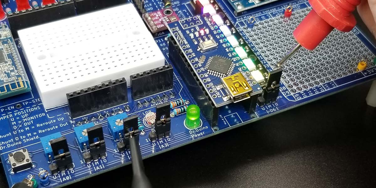
Figure 4 shows all the rerouting jumpers running along the top of the board.
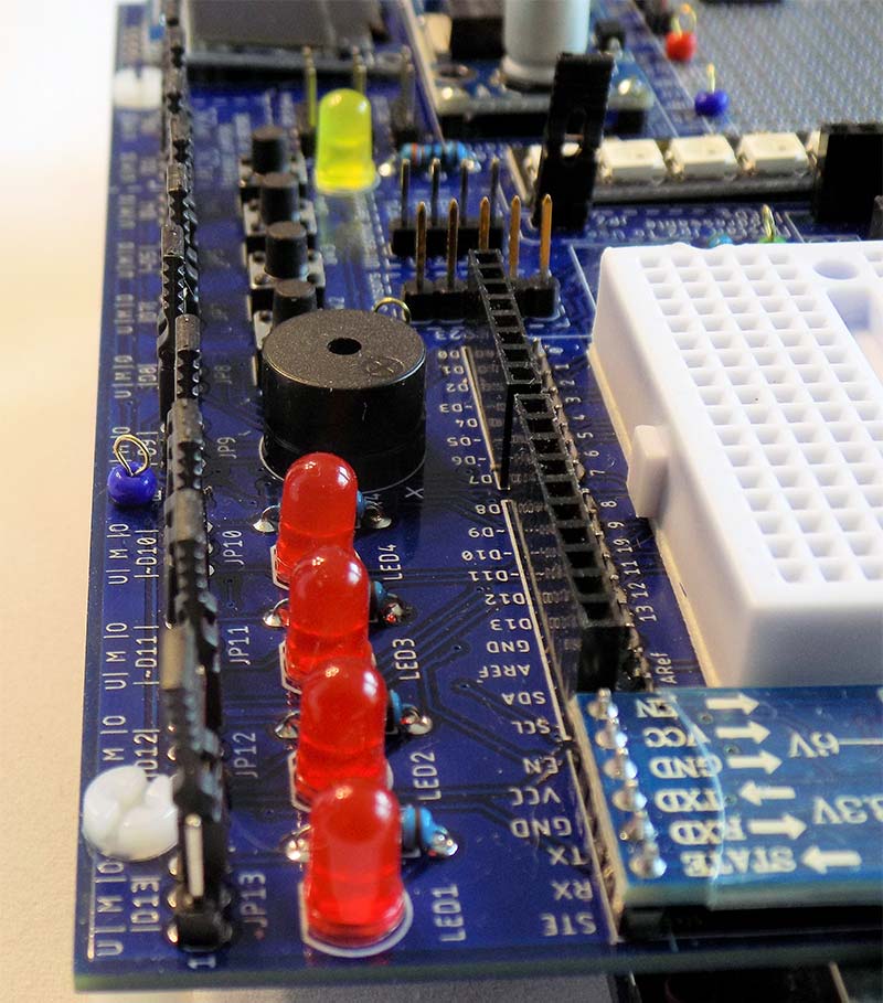
FIGURE 4. Jumpers and headers run across the top edge of the board for rerouting signals and disconecting onboard sensors.
Table 1 lists all the sensors and their associated jumper settings for more details. This table shows a list of digital and analog I/O pins that connect to the built-in sensors and their associated jumper designations. Note that analog pins A4/A5 are the hardware I2C pins that all tied together.
| Built-in Component |
Arduino Pin |
Jumper |
| Red LED 1 |
D13 |
JP13 |
| Red LED 2 |
D12 |
JP12 |
| Red LED 3 |
D11 |
JP11 |
| Red LED 4 |
D10 |
JP10 |
| 10K Potentiometer 1 |
A0 |
JP14 |
| 10K Potentiometer 2 |
A1 |
JP15 |
| 10K Potentiometer 3 |
A2 |
JP16 |
| Pushbutton Switch 1 |
D8 |
JP8 |
| Pushbutton Switch 2 |
D7 |
JP7 |
| Pushbutton Switch 3 |
D5 |
JP5 |
| Pushbutton Switch 4 |
D4 |
JP4 |
| Piezo Buzzer |
D9 |
JP9 |
| 2812 LED Strip (Power) |
- |
JP3 |
| 2812 LED Strip (Signal) |
D6 |
JP6 |
| Bluetooth Module - RX |
D0 |
JP0 |
| Bluetooth Module - TX |
D1 |
JP1 |
| Photoresistor |
A3 |
JP17 |
| OLED Display |
A4, A5 |
n/a |
| Ultrasonic Sensor |
A4, A5 |
n/a |
This table shows a list of digital and analog I/O pins that connect to the built-in sensors and their associated jumper designations. Note that analog pins A4/A5 are the hardware I2C pins that all tied together.
TABLE 1. Here’s a cross reference that shows which I/O pins are connected to the various onboard sensors and modules, as well as the jumper JPxx number controlling each connection.
If you don’t want to use or need one of the onboard sensors, you simply disconnect it by moving a jumper. You can also break a connection from any I/O pin to the breadboard area. This is useful if you have a strange voltage or other issue with an I/O pin and want to measure it out of circuit.
No need to pull wires out of your breadboard or unsolder wires on your shield. Simply remove the jumper.
You can even use a header with a jumper wire to route a signal to another I/O pin or to the prototype area. This rerouting scheme is probably the best feature of this board.
Interestingly, even the hardware UART RX/TX pins go through headers, creating an easy way to disconnect the Arduino IDE program after uploading. I’ve had at least one project in the past where I needed to use the hardware UART and this jumper scheme would have saved me a lot of time.
Some pins can’t be rerouted. In particular, the hardware I2C pins on analog pins A4 and A5. However, there really isn’t a need to do this because I2C devices share a common bus and are only activated by sending an I2C address.
In fact, the OLED display and ultrasonic rangefinder are tied together using the same I2C pins. Nothing prevents you from adding your own I2C device to this shared bus, as long as your I2C device uses a different address.
There are additional multiple headers for I2C devices that are meant to be used with the Expansion Pack (sold separately). However, just about any I2C device of your choice can be “Dupont-wired” into these headers.
Figure 5 shows the headers. The pin functions are clearly marked on the silkscreen.
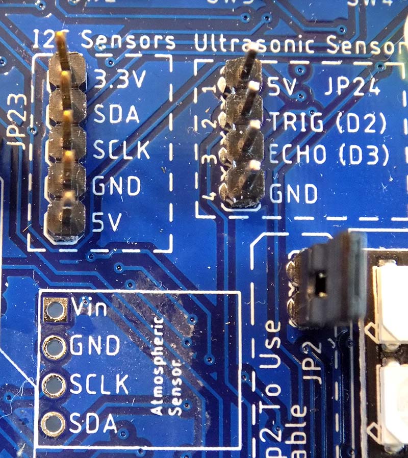
FIGURE 5. Headers for connecting Expansion Pack sensors or use for connecting your own I2C devices.
Summary
I’ve got to admit I’ve never used any Arduino learning kits or demo boards before. Maybe I’ve done too many Arduino projects to get any benefit out of them.
While you can look at the Explorer as another beginner’s board, after working with it for a while, I look at it as a troubleshooting tool to help me fix hardware problems and get my project done faster.
And the faster I get it done, the faster I can start my next Arduino project! NV
Go to www.DrDuino.com/nvreview now for all the details!