Years ago, I worked with an instructor who, right after being hired in my department, wanted to teach the senior level Electronic Communications course, and was unhappy to learn he would instead be teaching Introductory DC and AC Circuits to the freshmen. Our department chairperson believed that you must have a good grasp of the basics — especially DC and AC circuit analysis — before you can appreciate more complex circuits.
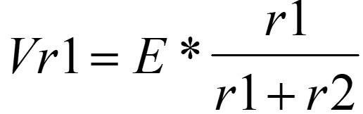
While I taught DC and AC circuits for many years, I always tried to relate to the students why they needed to understand a concept or why they would need to know this or that analysis method. For example, something as simple as the voltage divider equation for two resistors (R1 and R2) in series across a voltage source of E volts gives the students a chance to be analytical. For example, the voltage across R1 is:
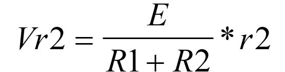
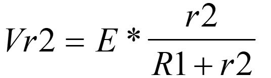
The equation is not just a simple way to save time while doing calculations. Understanding how the equation works and where it came from indicates good familiarity with series analysis concepts. I show the students how to derive the equation by using variables in their equations and not numbers. When you solve for the voltage across R2, you get:
I ask my students if they see similarities between the two equations and then explain that you can also rearrange the terms and see the same equation from a different point of view:
Now, instead of Vr2 being the voltage E multiplied by the ratio of resistors, it equals the circuit current multiplied by r2 (which is just a form of Ohm's Law: E = I * R).
So, we can see that knowing algebra is an important part of being able to derive, examine, and understand the equations we work with.
When the students take their first electronics course (after completing DC and AC circuits), they study the common-emitter amplifier shown in Figure 1.
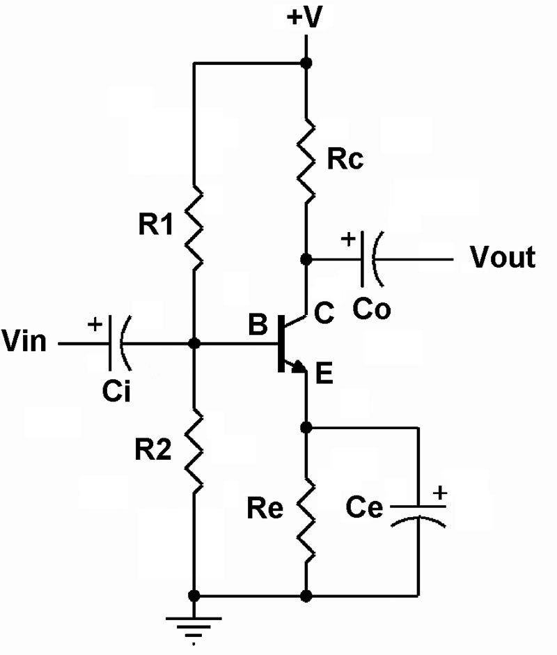
Figure 1. Common emitter amplifier using bipolar junction transistor and voltage divider biasing.
I explain to them that the circuit contains a voltage divider subcircuit at the base of the transistor that is used to create the DC bias voltage for the transistor's Q point. Thus, the voltage divider equation from DC circuits now becomes important in the electronics course while studying amplifier circuits.
When DC analysis turns into AC analysis, things can get more complex because the nature of the inductors and capacitors we use in the circuits will vary their response as the circuit frequency changes. Thus, instead of just considering a DC voltage or current, we may have to calculate and examine a range of voltages or currents.
For instance, the common emitter amplifier in Figure 1 will have a frequency response dictated by the value of the coupling capacitors Ci and Co, as well as the input and output resistance of the circuit and the midrange gain.
For someone looking at the circuit for the first time, just knowing some basics about the capacitor helps to begin the analysis. Recall that a capacitor looks like an open circuit when a DC voltage is applied. So, in terms of the DC analysis of the amplifier circuit, we can ignore the coupling capacitors and concentrate only on the four resistors biasing the transistor.
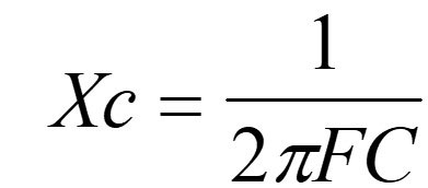
When we switch to AC analysis, the value of the coupling capacitors will help determine the minimum and maximum frequency of operation. We go back to AC circuits for the equation that predicts a capacitor’s reactance at any frequency:
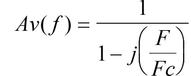
In addition, knowledge of passive filters — both low-pass and high-pass — is also necessary, since the coupling capacitors form passive filters at the input and output of the amplifier circuit. On the input side, this will involve use of the gain equation for the high-pass filter:
Now we have ventured into the area of complex numbers, which contain both real and imaginary components. Again, we see that a good understanding of algebra is essential to electronic circuit analysis.
As the students continue with their electronics coursework, they make their way to operational amplifiers. Once again, here is a chance for the algebra-loving students to show their stuff.
In Figure 2, we see the schematic for the difference amplifier.
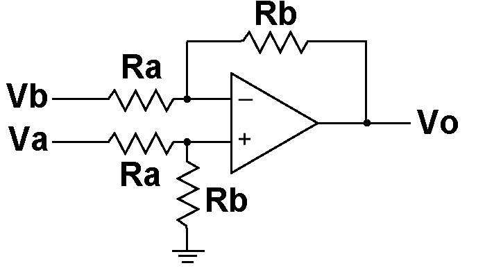
Figure 2. Op-amp configuration amplifies the difference of the input voltages.
The equation that predicts the output voltage is as follows:
Here’s another chance to deepen our understanding of the circuit by deriving the Vo equation from simple things we know. For example, two important characteristics of the op-amp are: (1) the inputs do not draw any current; and (2) the amplifier will try to maintain a zero volt difference across its inputs when negative feedback is employed.
In other words, the same voltage should appear at both inputs when negative feedback is used. Who knows what this voltage is and, in fact, it will change when the inputs change, but it’s safe to label the voltage at the inverting and non-inverting inputs with the same variable such as Vx since they both have the same value.
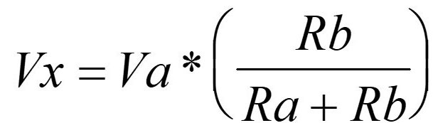
Now if you look carefully at the non-inverting input, you should see that, once again, a voltage divider configuration is present in our circuit. This allows us to write an equation for Vx at the non-inverting input that looks like this:
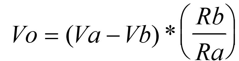
Looking again at the schematic, do you see a voltage divider configuration involving Vb and Vo? The two resistors between Vb and Vo will obey the voltage divider principle as well, giving us this slightly more complex equation:

The (Vb - Vo) term tells us the voltage across the two-resistor pair. This is the voltage that divides across the two resistors. The voltage across Rb that helps create Vx floats above the Vo level, which is why we must add Vo to the equation.
Note that if you replace Vo with zero in the equation, it reduces to the original voltage divider formula.
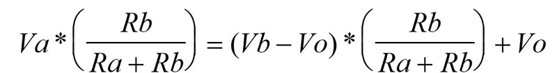
So, a few simple circuit techniques give us two equations. Now it’s a matter of algebra to reduce them. First, we set the equation equal to each other, eliminating the Vx variable:
Next, we multiply by the common term (Ra + Rb) to get rid of the denominators:

Then, we distribute some products:

The Vo * Rb terms cancel. Now, we rearrange the terms a little:

After factoring, we’re almost there:
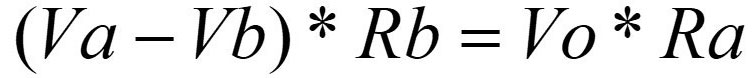
Dividing both sides by Ra now gives us the final equation. Again, a few simple DC techniques and a bit of algebra has helped us analyze a complex circuit.
Conclusion
Does the simple stuff ever go away? I’m afraid not. When studying digital-to-analog converters, the R-2R ladder circuit and its associated current division is an important part of the circuit. And the voltage divider comes back again when analyzing a DC power supply with constant output voltage. The voltage divider senses the output voltage and inputs it to an op-amp to adjust the output voltage accordingly.
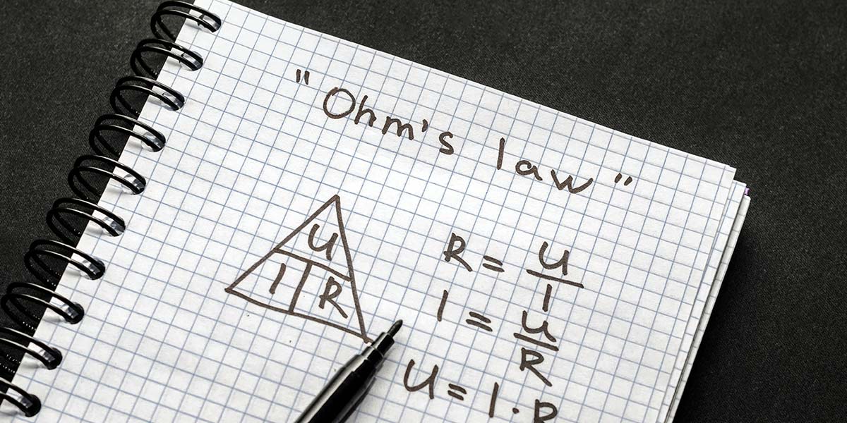
When studying digital circuits, just knowing Ohm's Law helps to understand the operation of a pull-up resistor. Recall that a pull-up resistor is used on a digital input to make a good logic one voltage level. How can Ohm's Law help answer the following question: Which resistor is a better choice for a pull-up: 4.7K ohms or 100K ohms?
The Ohm's Law equation: E = I * R becomes important in determining the answer. The input will require a small amount of current to flow through the pull-up resistor. If the resistor is too large, the voltage drop across the pull-up resistor may not leave enough voltage for the input to make a good logic one level.
Clearly, knowing the basics of DC and AC circuits leads to a better understanding of higher-level circuits and aids in their analysis, as well as exercises math skills necessary to find solutions during sign and analysis.