Most of the opening episode of this mini-series described the basic nature and behavior of light, with particular regard to its use in modern optoelectronic systems. The remaining part of that episode dealt with two types of light-beam manipulators, namely, mirrors and retroreflectors.
This installment continues the ‘light-beam manipulators’ theme by describing the nature and behavior of optical prisms and lenses.
LIGHT-BEAM MANIPULATORS
PRISMS
In optics, a prism is a block of transparent material having two or more plane (flat) surfaces. Prisms have an innate ability to bend the paths of light. A flat sheet of glass is a very simple prism.
When light travels through a transparent material or medium other than free space, its velocity (υ1) and wavelength (λ1) are lower than those that pertain in free space (υ0 and λ0). The ratio υ0/υ1 or λ0/λ1 is known as the medium’s refractive index, and is notated by the symbol n.
Figure 1 lists some typical n values for various transparent media, including normal glass (n = 1.5 to 1.9), which is transparent to all visible light and much of the lower IR spectrum, but blocks most of the UV spectrum.
| Substance |
Refractive Index |
| Free Space |
1.000 000 |
| Air |
1.000 293 |
| Ice |
1.31 |
| Water at 20°C |
1.333 |
| Glass |
1.5 to 1.9 |
| Diamond |
2.42 |
FIGURE 1. Table listing typical refractive index values for various transparent media.
Figure 2 illustrates the effects that ‘refraction’ has on a light ray when it travels through a pane of glass with (for simplicity) an n value of 2. In Figure 2(a), the beam enters the glass at an incident angle of 0°, is slowed down (thus reducing the light’s wavelength, but not its frequency) as it passes through the glass, and then returns to normal ‘through air’ speed as it leaves the glass at an angle of 0°.
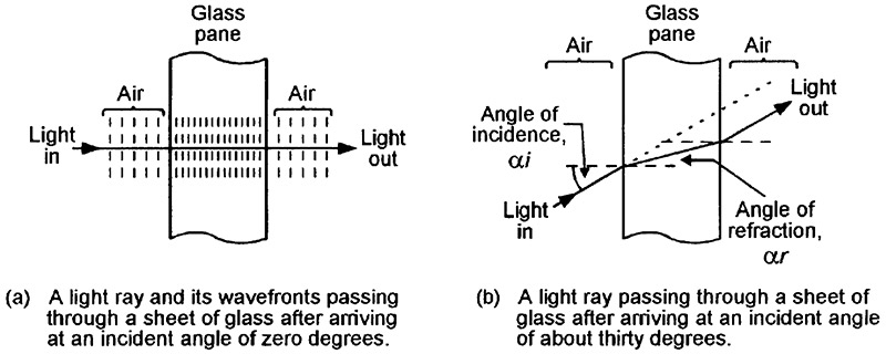
FIGURE 2. Diagrams illustrating the effects of refraction through a sheet (pane) of glass.
In Figure 2(b), the dashed lines represent the normal or zero degrees angular reference line. In this diagram, the ray enters the glass at an incident angle (αι) of (say) 30° and then, as it passes from the thinner medium (air) to the denser one (glass), the ray bends towards the normal by a refractive angle (αr) of about 15°; when the ray passes from the denser to the thinner medium again as it leaves the glass, the ray bends away from the normal again, returning to its original angle of 30“, thus obeying the basic Laws of Refraction. The values of αι, αr, and the n values of the incident (nι) and refractive (nr) regions are related by Snell’s law of refraction, which states that nr/nι = sin αι/sin αr.
Note in Figure 2(b) that the light ray leaving the glass is shown parallel with — but offset from — the path of the original input ray, which is indicated by the dotted line. The degree of offset (parallax error) increases with the angle of incidence and with the thickness of the glass. Simple mirrors — in which light rays enter and leave the mirror via the same glass surface — are subject to this type of parallax error.
Most prisms have plane surfaces that are angled away from each other, as shown in Figure 3, in which two prisms each have their major surfaces angled at 30° to one another.
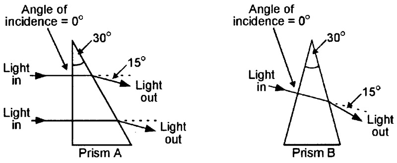
FIGURE 3. Diagram illustrating some important ray-bending features of a simple prism.
This diagram shows the effects that the prisms have on a light ray that arrives at an incident angle of zero degrees. In both cases, the ray passes cleanly through the glass without bending but, on leaving the glass, the ray bends away from the normal by about 15°, thus obeying the basic Laws of Refraction.
Note in Figure 3 that the degree of ray bending is independent of the thickness of the prism glass and (ignoring n value effects) is determined mainly by the angle of incidence of the ray and by the angular difference between the prism’s input and output surfaces.
Regarding the ‘n value effects’ mentioned in the above paragraph, it is important to note that the refractive index values of all transparent media other than free space vary with the wavelength of a light, and increase as wavelength shortens. The refractive index of glass is normally measured using a yellow sodium light with a wavelength of 589nm; the actual index value is higher than normal to violet light (400nm wavelength) and lower to red light (700nm wavelength).
Figure 4 shows, in exaggerated form, the results of passing a narrow beam of white light through a symmetrical triangular prism.
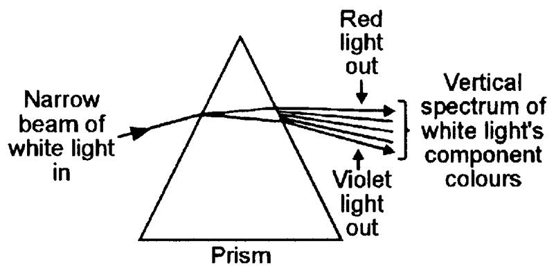
FIGURE 4. Exaggerated diagram showing a prism splitting a beam of white light into its component colors.
White light contains all the colors (wavelengths) of the visible spectrum, and the prism thus (because its refractive index is wavelength-dependent) bends each individual color of the beam by a different amount, giving the least bend to red light and the greatest bend to violet light. The prism’s output thus takes the form of a vertically-expanded colored spectrum. This scattering of white light’s component colors is known as dispersion.
When a ray of light passes through air and enters a prism, it bends by an amount determined by its angle of incidence and by the refractive index value of the glass. When the ray leaves the prism again and returns to the air, it bends by an amount determined by its angle of incidence and by the refractive index of the air (1.0) divided by that of the glass (say 1.5), and this value is invariably less than zero (0.667 in this example). Figure 5 shows the actual amounts of output refraction that occur on three different prisms that each have a refractive index of 1.5.
In Figure 5, the ray strikes the output surface of prism A at an incident angle of 30° and leaves the prism at a refractive angle of 42°; this prism thus bends the ray downwards by 12°. In the case of prism B, the ray strikes its output surface at an incident angle of 40° and leaves at a refractive angle of 85°, thus bending the ray downwards by 45°.
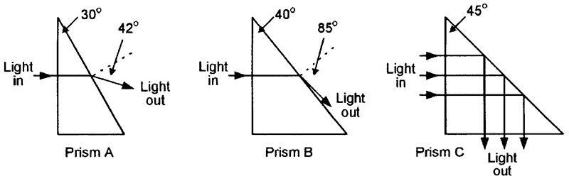
FIGURE 5. Diagram illustrating the phenomenon of total internal reflection in a prism.
Note in the case of prism B that the ray leaves the prism at an angle that is only 5° less than the angle of slope of the prism’s output face, and it is obvious that if the angle of incidence is increased much more, the ray will be unable to penetrate the prism’s output surface. The angle of incidence at which this occurs is known as the surface’s critical angle, and is dictated by the n value of the glass; the critical angle is 43° at an n value of 1.5, 36° at an n value of 1.7, and 32° at an n value of 1.9.
Figure 5 shows, in the Prism C diagram, what happens to the light rays when they strike the prism’s output face at an incident angle of 45°, i.e., at an angle greater than the critical angle of the surface. Under this condition, a phenomenon known as total internal reflection occurs and makes the internal surface act like a mirror that bends the rays by double their angle of incidence, thus (in this case) bending them through a 90° angle and projecting them through the lower face of the prism.
The internally-reflecting type-C prism thus acts like a mirror that bends light through 90°, but (since the light passes through separate input and output surfaces) does not suffer from parallex errors. This type of prism is widely used in high quality optical instruments and devices such as reflex cameras, binoculars, and automatic laser-aiming controllers.
Total internal reflection can occur whenever one transparent material interfaces with another that has a lower refractive index, thus giving a less-than unity refractive index and a positive critical angle value at the interface junction. All modern fiber optic cables rely on this ‘internal reflection’ basic principle for their very efficient low-loss operation (fiber optic cable principles will be described in Part 3 of this series).
LENSES
Normal optical lenses are light-bending refractive devices that are related to prisms but have curved (rather than flat) faces. Figure 6 shows the classic profile of a simple lens that has two parallel faces that are each radially curved in two dimensions, to form a section of a sphere. This type of lens can focus a parallel bundle of light rays onto a single point (the focal point), as shown in Figure 6(a); the distance between the center of the lens and the focal point is the focal length of the lens.
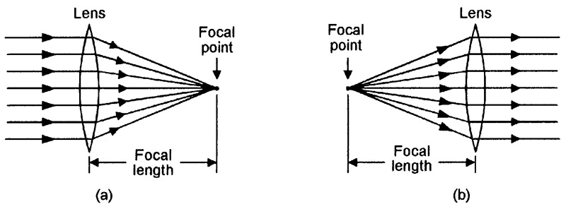
FIGURE 6. A simple lens can (a) focus a parallel bundle of rays onto a single point, or (b) convert the rays from a single point source into a parallel (collimated) beam of light.
If a light point-source is spaced from the lens by a distance equal to the focal length of this type of lens, the lens converts the light into a parallel (‘collimated’) beam of light, as shown in Figure 6(b).
Figure 7 shows the basic way of using two simple lenses in a light-beam alarm or communication system. At one end of the system, the left-hand lens converts the transmitter’s light point-source into a collimated (parallel) light beam and, at the other end of the system, the right-hand lens converts the collimated beam back into a point of light, which is applied to the receiver’s light-sensitive input. Identical lenses are used in the collimating and decollimating processes.
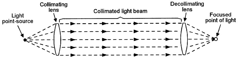
FIGURE 7. Basic way of using two lenses in a light-beam system.
Systems of the above type only generate a perfectly parallel beam if the light point-source is infinitely small, and this is an impossibility. In practice, the beam widens with distances after leaving the collimating lens; the amount of widening is proportional to the width of the light source and inversely proportional to the diameter of the lens. For minimum widening, the lens diameter must be large relative to that of the source.
Simple lenses with one or both faces shaped as a section of a sphere are known as spherical lenses and are available in convergent and divergent types; convergent types make a parallel beam of light converge towards a common focal point; divergent types make a parallel beam of light diverge outwards. Figures 8 and 9 show a variety of lenses of these types.
Figure 8 shows four simple types of convergent spherical lens. The thin biconvex lens shown in (a) is the same type as shown in Figure 6; it operates equally well either way around, but its sharp edges are rather fragile. The thick biconvex type shown in (b) gives the same performance as the (a) type, but is more rugged.
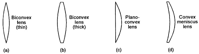
FIGURE 8. Four simple types of convergent spherical lens.
The plano-convex type shown in (c) has one flat and one curved face and must be used the correct way around, with the flat face pointing in the direction of the parallel light beam and the curved face aimed towards the light’s focal point. The convex memiscus type shown in (d) has a very long focal length; it is the type used in most spectacles and contact lenses.
Figure 9 shows three simple types of divergent spherical lens. The biconcave lens shown in (a) can be used either way around, but the plano-concave type shown in (b) must be used the correct way around. A concave meniscus type is shown in (c). Lenses of these various types are often used in conjunction with convergent lenses, to make high-quality compound lenses (as described shortly).
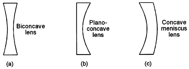
FIGURE 9. Three simple types of divergent spherical lens.
Most spherical lenses are of the simple type already shown, but other types are also available. The cylindrical biconvex lens shown in Figure 10(a), for example, is curved in one dimension only, and is used to focus a parallel light beam into a thin line, rather than a spot, or to convert a thin line of light into a collimated beam.
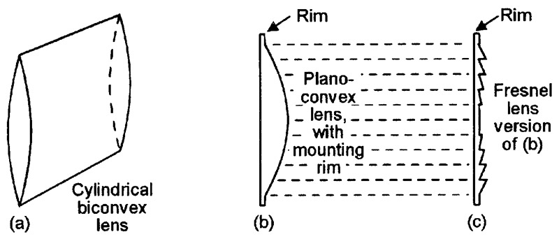
FIGURE 10. Three special types of spherical lens.
In most normal lenses, much of the sub-surface glass or plastic lens material performs no useful function. A Fresnel lens is one in which most of the non-useful lens material is removed, to make a lightweight or low-cost lens that performs almost as well as a normal lens in simple ‘light-beam’ types of application. Figures 10(b) and (c) show — in cross-section form — how a plano-convex lens with a mounting rim is transformed into its Fresnel equivalent. Here, the Fresnel lens is made up by effectively dividing the original (b) lens into 10 horizontal slices, removing the ‘dead’ material from each slice, and then bonding the remainder onto a base of identical material that also acts as the lens rim. In practice, most Fresnel lenses are molded, in plastic or glass.
The focused images generated by simple spherical lenses suffer from spherical and chromatic defects or abberations. Spherical abberation makes a straight line appear curved in the focused image; if you wear spectacles, you can see a demonstration of this effect by standing in front of a set of library shelves and noting how the shelves above and below your eye level appear curved when you have your glasses on, but not when they are off.
In simple lenses, chromatic abberation makes faint colored fringes appear around focused white or multi-colored images. The effect occurs because the refractive index of the lens material (and thus the focal length of the lens) varies with the color of light, as shown in Figure 11(a), making it possible to sharply focus only a small slice of the color spectrum; the rest of the spectrum is out of focus, producing the ‘fringe’ effect.
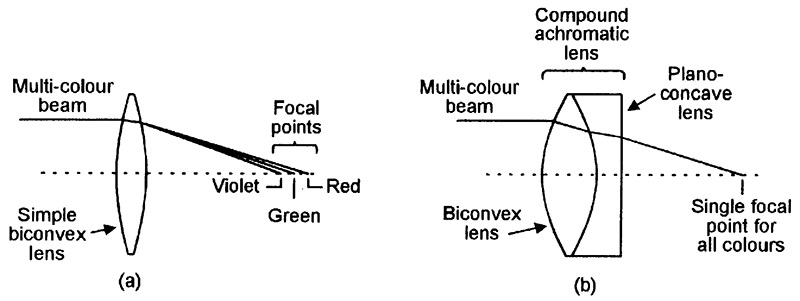
FIGURE 11. The compound achromatic lens shown in (b) is designed to minimize chromatic aberration of the type suffered by the simple (a) lens.
This problem can be overcome by using a compound lens made of one converging and one diverging lens, each with a different refractive index value, as shown in Figure 11(b). Such a lens can be made to give all colors the same overall focal length, and is known as an achromatic or antispectroscopic lens.
The strangest and most recently developed lens is the graded-index (GRIN) rod lens, which is used in modern fiber optic applications and operates in a different way to a normal lens. A GRIN rod is a glass or fiber rod that has a refractive index that decreases progressively with distance from the rod axis. This index variation causes light rays to follow a sinusoidal path as they travel along the rod, as shown in Figure 9(a). The length of one complete sinusoidal cycle in the rod is called the pitch (P) of the rod; the P value is determined mainly by the rod’s diameter and refractive index profile; the value is typically about 20mm.
A GRIN rod lens is simply a slice of GRIN rod with a length less than a single pitch-length, so that its optical output signal is out of phase with the optical input signal. The most interesting and widely used GRIN rod lens has a quarter pitch (giving it a length of about 5mm) and has the interesting properties illustrated in Figures 12(b) and (c).
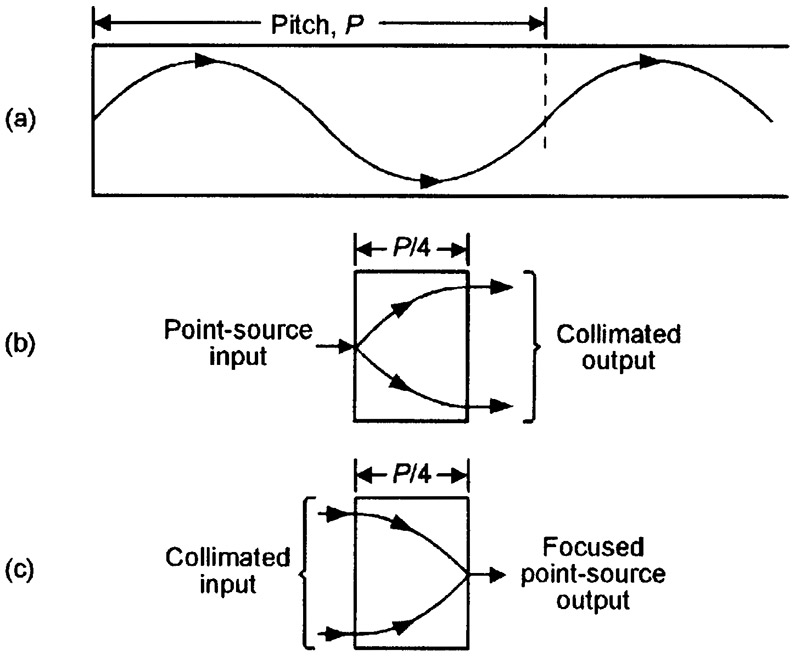
FIGURE 12. Light rays follow a sinusoidal path through a graded-index (GRIN) rod (a). A quarter-pitch GRIN lens collimates the light from a point-source (b), and focuses a collimated light beam into a point (c).
Note in (b) that the light from a point source in contact with the center of the left face of the lens emerges from the right face in fully collimated form and, in (c), that a collimated light beam entering the left face leaves the right face as a focused spot. The GRIN rod lens thus has some properties of a conventional lens, but has a very short focal length.
GRIN rod lenses are widely used in modern fiber optic and laser module applications. Figure 13 shows an example that illustrates the advantages of a GRIN rod lens over a spherical lens in a simple fiber optic application in which the fiber optic cable’s point-source ‘light’ output needs to be collimated when fed into the outside world.
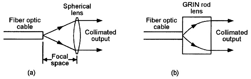
FIGURE 13. Method of collimating the light output from a fiber optic cable using (a) a spherical lens and (b) a GRIN rod lens.
In the case shown in (a), the light is collimated by a conventional lens, which must be placed a precise fixed distance from the end of the cable, to which it is coupled by an air gap. In the case shown in (b), the GRIN rod lens is simply bonded directly to the polished end of the cable, and no carefully spaced air gap is required.
More information on fiber optic and GRIN (graded index) operating principles will be given in the next part of this series, which will give an in-depth explanation of fiber optic principles and practice. NV