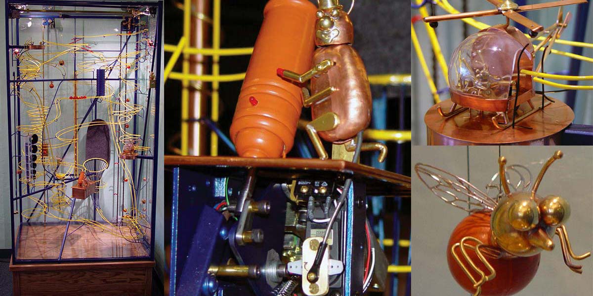
These are the sounds of “The Flying Marbellos” — a rolling ball sculpture with marbles and small metal “bugs” to run the show.
FIGURE 1. The Flying Marbellos. (See the video at the end)
The purpose of a rolling ball sculpture (RBS) is to transport balls to the top of a system of tracks, where they proceed to find different and amusing paths on the way down. Is this a silly thing to do? Yes! Do people love to watch these things for long periods of time? Yes! Put an RBS in a public place and you’ll attract a crowd surrounding it. I love watching mechanical things, but building this turned out to be even more fun.
Since I have a fascination for mechanical things, and also enjoy working with BASIC Stamp microcontrollers, this 6-1/2 foot tall RBS finds some different ways of going up with the balls, as well as going down. It all starts with a motor that elevates the marbles to the top, and as they roll down, they encounter switches that change paths with every marble. The insects and spiders add a circus flair to the whole thing. A helicopter carries one marble from a low platform to a higher one so that it can begin another journey down. An elevator carries another marble to the top, sends it to drop through the air to a pad where it bounces up and into a basket. One marble lands into the muzzle of a cannon, where a bug lights a torch, leans over, and lights the cannon’s fuse, and then the cannon fires the marble into the basket. Two marbles at once go down into a tube, where 90 LED lights follow the marbles, cascading in sequence down the tube. Others follow turns, loops, and spirals, jump from a ski jump, and ring bells on their way down.
Once in a while, a marble leaves the track and does not make it back on to the track. When this happens, a marble-rescuing machine takes the marble back up and puts it back on the track. Some RBSs are excellent at keeping all balls on the track for extended periods of time. When marbles bounce, jump, or get shot out of a cannon, this doesn’t work as predictably. The marble rescuer keeps the machine going, despite losing its marbles now and then. It hasn’t stopped me from losing my marbles, though. I noticed that if no marbles go onto the bottom for a while, observers start getting anxious to see it happen again, so that they can watch the rescuer put the ball back on the track. Maybe losing your marbles is not such a bad thing.
Gravity makes the marbles come down the tracks, and three BASIC Stamp microcontrollers help with the 21 switches, four stepper motors, one servo, and 92+ LEDs. I chose BASIC Stamps because they are so easy to use. Their online manuals and resources gave me plenty of information to learn to work with them, without my being an engineer. Coordinating the motors and moving parts required many changes of the program to get the right “look” and the right smoothness. With the Stamps, it was easy to make changes and evaluate their effects.
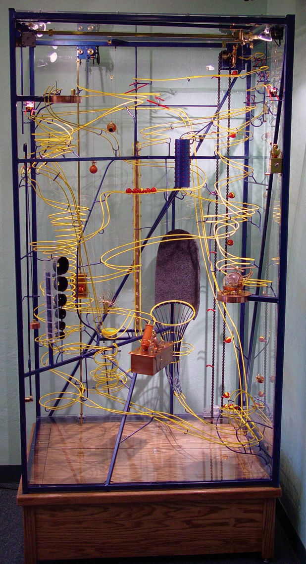
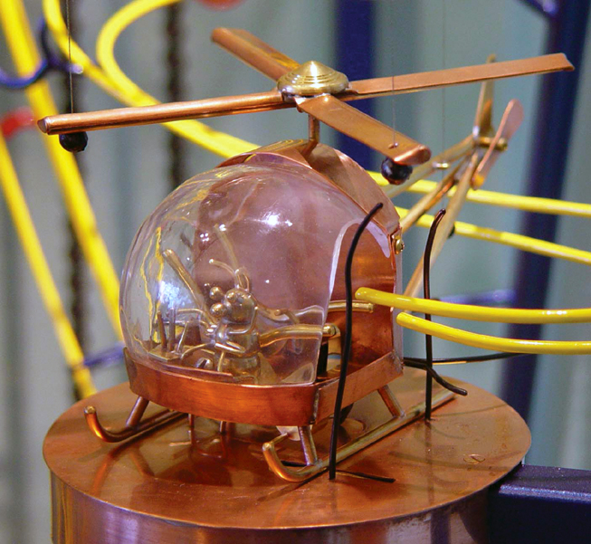
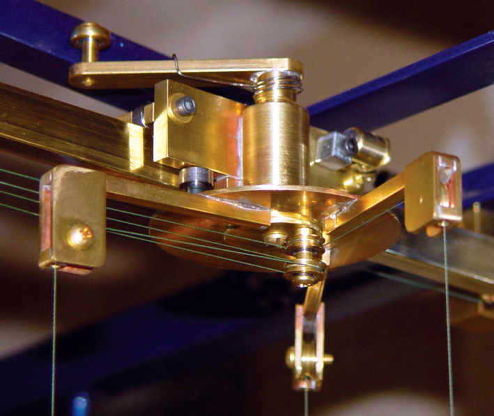
The Helicopter
FIGURE 2. The helicopter.
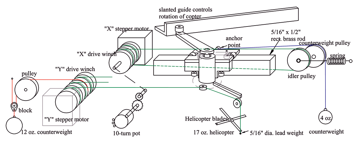
One of the big stars of the show (and certainly the biggest challenge) is the helicopter. When a ball rolls into the cockpit of the helicopter, it flies by means of fishing line leading to a trolley above. One stepper motor for the “X” (horizontal) direction of travel pulls the trolley on a track across the top of the machine. Another stepper motor raises the copter (the “Y,” or vertical direction) so that when the two motors work together, they lead it on an arc to the upper platform. As the trolley travels from one side to the other, it also rotates the copter, so that at the top it is facing 90° from where it started. (See Figure 3.)
FIGURE 3. Helicopter schematic diagram.
You might think that since you can control the speed of stepper motors, that you would have complete flexibility in controlling motion. There are some limitations. The motor’s maximum speed of rotation is limited because they only work properly up to a maximum speed of the steps, and then the mechanics can’t keep up with the electronics. With a “PAUSE 1” in between steps in the program, this comes close to the top speed of the motors I used, which have 200 steps per revolution. To get a fast enough maximum speed of motion, some mechanical advantage is needed. Using motors with fewer steps per rotation would also increase speed but sacrifice some smoothness in movement.
FIGURE 4. The winch reel
Each motor turns a drum that is a winch for the control lines (Figure 4). The diameter of each area that winds up a line affects the speed of motion. Most of my lines wind onto .770” diameter, which gives the speed that I want. When you use a larger diameter winch, this puts a heavier load on the motor. By using a counterweight, the motor just moves the load and does not have to lift it all. So then, at the same time that the winch is winding up control lines that raise the helicopter, part of the winch is unwinding a line going to a counterweight. This counterweight lightens the load for the motor, and also balances the system so that when the power goes off, the copter remains in position instead of crashing. If the winch area for the counterweight is turned to a smaller diameter, then the weight will not travel as far. This will also require more weight, but means that the path of the traveling counterweight is shorter and can fit into a smaller area. I used a block with one counterweight to reduce the counterweight travel to half the distance.
FIGURE 5. The bee counterweight.
The motor controlling the “X” direction turns a drum that pulls the trolley toward it. The line attaches to the trolley, continues to an idler pulley, and then returns to the drum where it unwinds on another part of the drum. The ball-bearing idler pulley keeps tension in the line with a spring. As the line winds in one spot and unwinds in another, the pulley moves about 1/4” as it keeps tension on the line. The line is 50 lb.-test multifilament “Spiderwire Stealth” fishing line (Wal-Mart). This multifilament line is thin, strong, Teflon lubricated, and it is limp — it has no “springiness” to make it misbehave. The action of the “Y” mechanism makes the trolley want to go to the left, so a counterweight pulls the trolley to the right to offset this.
The motor controlling the “Y” direction winds up three lines (16 lb — Spiderwire) on its drum winch to raise the helicopter, while unwinding another 50 lb. line going to a counterweight. The lifting lines attach to three points on the helicopter, and then lead up to a “Y” shaped yoke, where the lines turn around pulleys, lead to more turning pulleys in the center of the yoke, and then go to the winch. Since the yoke rotates as the helicopter travels, the turning pulleys in the center of the yoke keep the relative lengths of the lines from changing, which keeps the copter level while flying. The lines attach to the helicopter by going through a hole and attaching to a lead crimp-on fishing weight. When the copter lands, the weights can drop and keep tension on the lines so that they all stay on their pulleys. All of the pulleys use ball bearings.
The trolley is made of pieces of brass soldered together, with six bearings to ride the rail — two on top and two each on front and back (Figure 6). I tried making this trolley with a brass sleeve to ride the rail (as I did the elevator and rescue device), but there was too much friction. The helicopter rotation arm puts the center of weight off center from the rail, and the ball bearings are needed to make it travel smoothly enough.
FIGURE 6. The copter’s trolley at top.for copter “Y.”
The “X” motor also connects to a potentiometer, so that I can measure the position of the trolley with a Stamp. This is only for cases where power is lost, so that when power is restored, the copter can find its way back home. Otherwise, it is almost sure to crash when the power goes on. One way the power can go off is when someone thinks that the way to turn off electrical things is to unplug them (been there, done that). To ensure that this can’t happen during normal operation (turning it off with the switch), a relay holds the power on to the Stamps and motors until the copter lands. The spot lights and ball-lift motor turn off, but the helicopter finishes its journey before all shuts off. This feature was disabled during most of the development of this project, when I wanted the copter to stop if I switched it off.
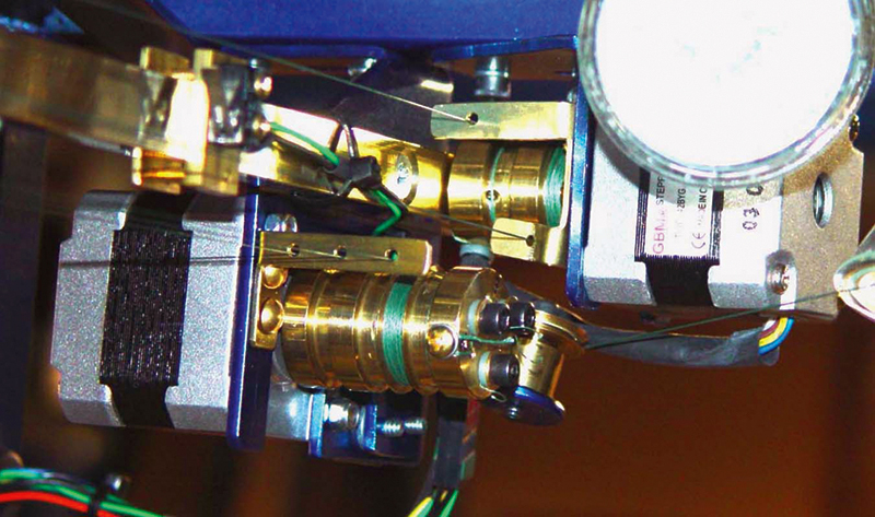
FIGURE 7. The helicopter’s drive motors. The Y motor is on the left, the X motor is on the right.
The pot is a 10-turn wire-wound pot that is connected by gears to the “X” motor. The gears make it so that the pot turns no more than its maximum 10 turns during the trolley’s travel. The “Y” Stamp can know where the trolley is with an RC circuit, and do the right thing with getting the copter home in the vertical direction. This is especially important near the top of the arc-shaped flight path, where “Y” may have to go up before it starts going down. I calibrated it by guessing some numbers for RC time, and having an LED flash different numbers of times for different positions. I then moved the trolley by hand and marked the positions where the number of flashes changed. It only took a few tries to get a scale of numbers corresponding to the trolley position. Limit switches tell me if the copter is at the ends of travel in the “X” direction, and if it is landed at its home landing pad. I did not use a limit switch at the upper landing, and instead used the precision of the stepper motors counting steps to determine the final position at the top landing. This works just fine, but if I had it to do again, I would have a switch there, too, as it would make programming the flight path much easier. Another switch detects if a ball has loaded into the helicopter. Leverage is needed to convert the tiny movement of a microswitch into a larger movement that a marble can easily trigger.
The flight path of the helicopter can be calculated and worked out before ever flying it, but it turns out that doesn’t help much. One needs to see it working to evaluate the speed and smoothness of the movements. You can get an idea by turning the winches by hand and counting the turns. Make an educated guess, and watch it fly. It becomes immediately obvious how to tweak the numbers to get on the right path. Getting it close is not too tough. Getting it just right is an art. The easy reprogrammability of the BASIC Stamp comes to the rescue.
The Stamp controlling the “Y” direction also controls the rescue device. When it is involved in a rescue, it signals the “X” Stamp that it is busy, so that both Stamps will be able to start together when flying the copter. The “X” Stamp tells the “Y” Stamp to start, but will not tell it until the “Y” Stamp no longer gives a busy signal. If one motor is trying to fly the copter while the other one is unavailable, all kinds of bad flying can happen.
I also made a hidden test button, which could be used to start partial flights. A quick push gives one flight path, and a longer push gives a different path. This was really useful when programming the flight path. In the final version, I use it to fly the copter only one way: to land on the top and stay there, which is useful for transporting the RBS.
When the helicopter lands at its temporary upper landing or at its home landing pad, there is some sway to it. Since it is important that it land predictably in the right place, there are guide rails to assist it. At the base of the copter is a “V” shaped guide rail on each side, and the bottom skids of the copter also assist in guiding. On the landing pads are vertical rails that guide it into position, one at the top pad and three at the bottom. They are made of 1/16” brass rod, and painted black to make them inconspicuous.
The Elevator
FIGURE 8. The elevator, about to release a marble. The blue post in the center dumps the marble cradle.
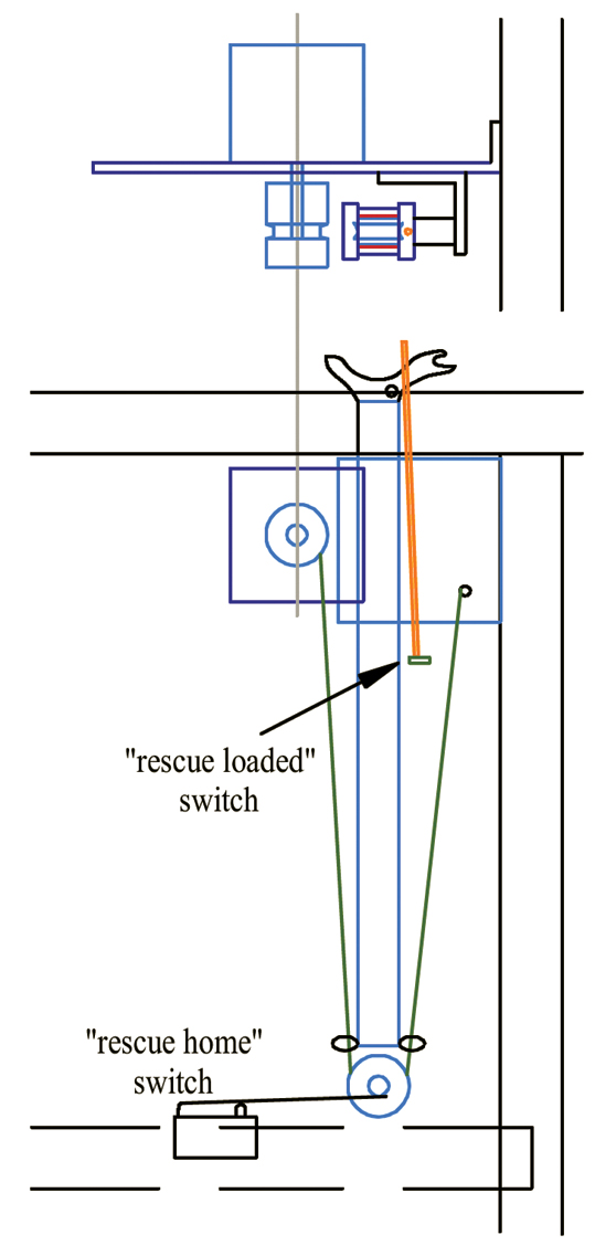
The elevator has a similar operation to the helicopter. A stepper motor winches the elevator up, while at the same time lowering a counterweight down (Figure 8). A guide pulley separates the elevator and counterweight far enough from each other so that they don’t hit each other during travel. Limit switches at the top and bottom tell the Stamp where the elevator is, and an “elevator loaded” switch tells when there is a marble in the elevator waiting to go up.
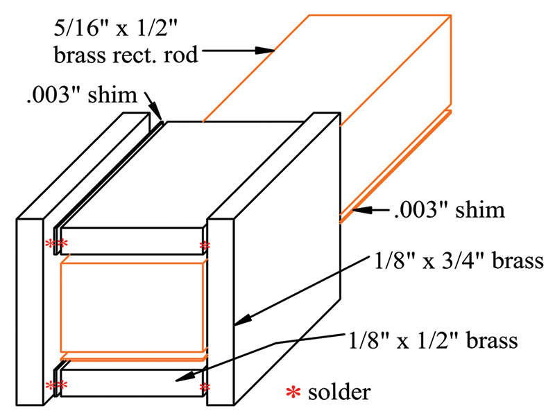
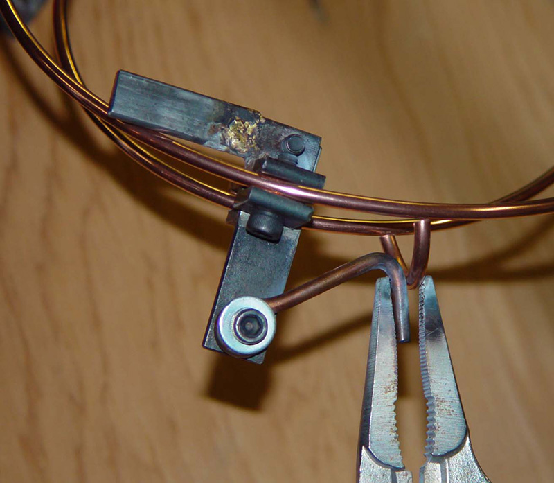
FIGURE 9. Slide for the elevator or the rescue device. The brass rectangular rod and the shim with it are removed right before soldering.
The elevator is attached to a slide that rides on the same kind of rail (rectangular brass rod) as the helicopter. The slide is soldered together out of pieces of brass (Figure 9). On one side some pieces of .003” brass shim are soldered in to give clearance. The whole thing is clamped together with it around the rail and another piece of shim. Then the rail and one shim are slid out, and it is soldered. It is important that the solder is flowed in from the outside, and in sparing quantities so that it doesn’t get inside of the slide. This gives a slide that is .003” bigger than the rail. When the motor lifts from the center of gravity of the elevator, and two coats of car paste wax are on the rail, it slides up and down easily.
The Rescue Device
The rescue device uses the same type of rail and slide, only this time the slide holds still, and the rail moves (Figure 10).
FIGURE 10. The rescue device.
A slower speed allows a smaller winch diameter, and the stepper motor is strong enough to operate it all without a counterweight. Limit switches detect when the device is at the bottom, and when it is loaded with a marble. I didn’t feel a switch was needed at the top of travel since the number of steps that the motor makes can govern this quite well. It just needs to start from the lowered position. It is then possible to finely tune the height when it is raised by changing the program on the Stamp.
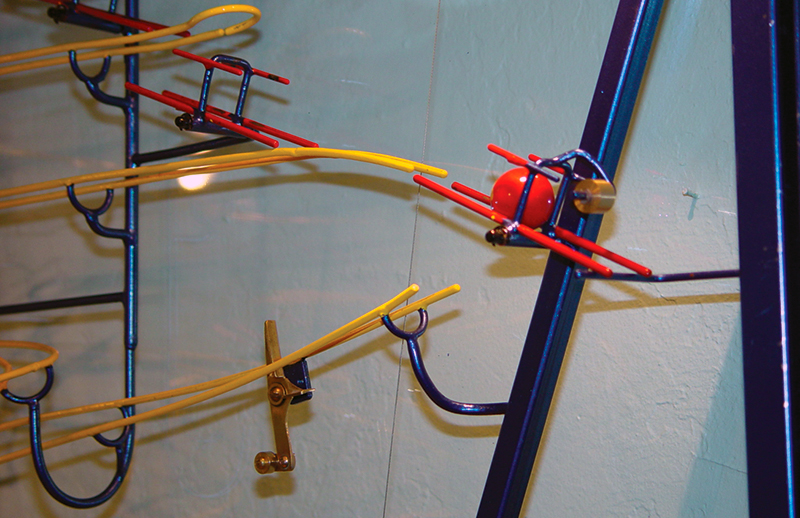
The Cannon
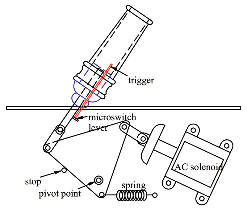
The cannon is shot by a 120 VAC solenoid, where a cam arrangement transfers the travel of the solenoid into pushing a rod into the bottom of the cannon (Figure 11).
FIGURE 11. The cannon mechanism.
I tried 12 VDC and 24 VDC solenoids to do this, but none of them were strong enough at the currents that I used to do the job. The AC solenoid gives 7 lbs. pull when it shoots the marble 6-15” high, and more would be better. It is triggered by a Triac driver (optical coupler) and a Triac. I thought that the Triac would give a predictable velocity to the shot since it always switches at the same place in the changing AC voltage, but this was not the case. I think the shooting power is variable because of less-than-perfect sphericity of the marbles, and less-than-perfect walls of the PVC pipe that I made the cannon barrel from. If one in 10 shots miss the basket, then we get to watch the ball rescue device in operation.
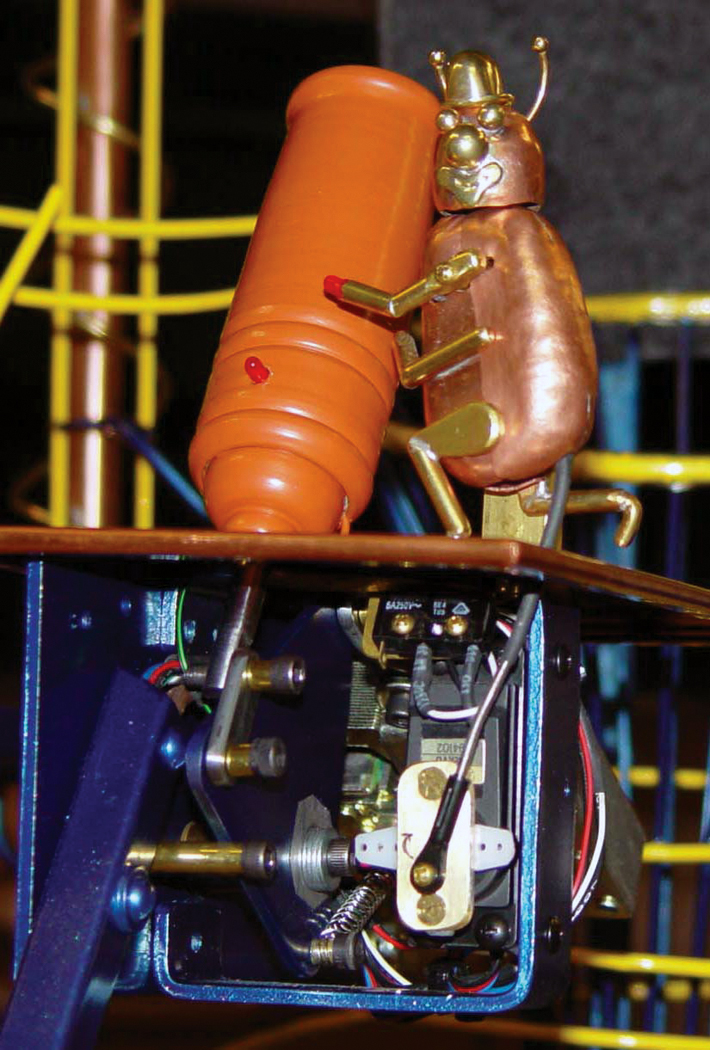
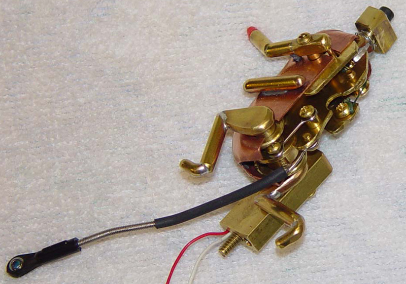
FIGURE 12. The cannon-lighting clown bug, and the servo underneath that moves him.
The cannon is “lit” by a circus clown bug. He holds an LED “match” in his hand. The match lights, and he leans over to light the LED “fuse.” As he leans over, he extends his match arm to light the fuse, kicks a back leg into the air, and turns his head 90° toward the cannon. A servomotor moves it all. The bug’s body movements are managed by the front of the bug rotating on a different axis than the back half of the bug. When he leans over, the relative motions of the two halves can make the arm, leg, and head move. This part of the project made me feel like a watchmaker. Do you think Mr. Rolex ever played with servos, LEDs, and bugs? Maybe not, but then he probably had all of his marbles.
FIGURE 13. The clown bug mechanism.
Servos need to be on a separate power supply than the BASIC Stamps. The servos draw a bit of power, and cause the voltage to drop enough to “brown out” the supply, which would cause a Stamp on the same supply to reset.
The LED Cascade
Ten circular rows of nine (5 mm) LEDs surround a tube through which two marbles travel. The lights follow the path of the marbles as the go down the inside of the tube. Actually, the first marble hits a microswitch before it gets to the tube, and the lights follow a predetermined sequence that appears to follow the balls. The mechanical marble switch that precedes this lets go of two marbles at once (Figure 14).
FIGURE 14. Marble switches. The one on the right waits for two marbles, which go through the marble separator to the left.
A marble separating mechanism is needed so that the two marbles are not right next to each other, to get the effect that I wanted. A tight spiral inside the tube makes the marbles go down the tube more slowly as they spin their way down.
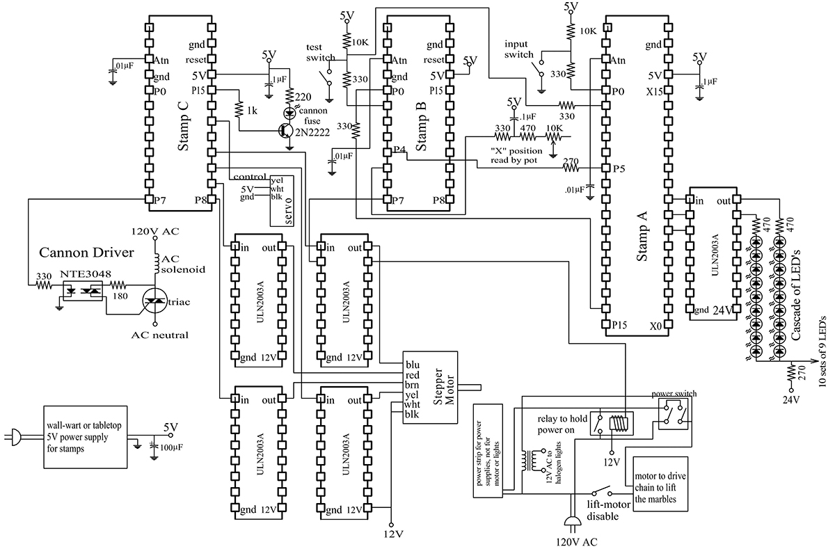
More Electronics
The whole thing (Figure 15) was wired with point-to-point wiring on a perforated circuit board with pads at each hole. A printed circuit would be nice, but since I made a lot of changes, additions, and deletions during the development, I think point-to-point was actually easier. Connectors were essential to be able to plug and unplug the board from everything else. Resistor networks would have been nice, if I had only realized from the beginning how many resistors of the same values would be used.
FIGURE 15. Circuit diagram. Only one input switch and one stepper motor are shown, since they all are wired the same. All pin connections are listed on the spreadsheet “pins & functions.pdf” available in the downloads at the end of this article.
I used three BASIC Stamps — each one to control several functions. This saved cost, but added complexity to have the microcontrollers alternating tasks. Using more Stamps would have raised the cost, but would also have saved a lot of time in getting all of the activities to coordinate with each other, and would simplify the programming. I used a BS2SX, a BS2p24, and a BS2p40. It all could have been done with four or more BS2s, but I used some Stamps that I already had on hand.
My power supplies were wall warts and table top supplies. The Stamps need an electrolytic capacitor across the output of their supply, to help avoid brown-outs and resetting. The spot lights are 12 VAC halogen reflector lights (a 35W and two 20W), using a power supply made for these.
Marbles, Tracks, and Construction
The tracks are all made of 1/8” diameter steel welding rod, brazed together. Semi-circular crosspieces keep the track spacing and give places for supports to attach.
FIGURE 16. The crosspiece jig holds the track at the proper spacing for brazing the crosspiece.
When one piece of rod is used, the next one is butted to it and brazed end-to-end. I made a bunch of jigs that hold the cross pieces in position for brazing to the track. They clamp on with 8-32 Allen cap screws. Tighten the screws with a 9/64” Allen ball driver, with a screwdriver-type handle. This tool will reach into and around a lot of tight places, and tighten the screws even when it is 25° out-of-line with the screw. RBS construction creates lots of tight places. Track can be bent by hand, pliers, and a vise. A wonderful bending jig can be purchased at Micro-Mark (www.micromark.com) Flower pots make good round forms in varying diameters for bending the rod. A great idea I learned a little too late for this RBS — fill a big traffic cone with cement. When it hardens, you have a heavy, stable place to bend many different diameter curves. All methods are useful, as each situation may require a different bending technique.
The tracks need to be banked so that a marble going around a curve does not fall (or fly) off. This is directly affected by the weight of the marble and the speed it is going when it hits the curve. The weight should be controlled by marble selection. The consistency of weight is more critical if the marbles bounce, leap, or get shot from a cannon. Buy 100 marbles, weigh them, and sort them into piles. See what weight range has the most marbles, and with luck there will be 20 marbles that are within 0.2 grams of each other. Use these “official” marbles to operate the RBS. Now save a slightly heavier and a slightly lighter marble for testing. An official marble may negotiate a curve almost every time, but the lighter and heavier ones find the curves that are banked almost right, and help you figure out whether they need more or less bank. Test each foot or two of track as you make it, as it is a lot easier to change the angle of bank before too much track comes after it. The track spacing affects the speed: wider makes the marble roll slower, and makes banking less critical. Narrower spacing makes the marble roll faster, but the angle of bank on the curves is more critical, and it is easier for the marble to leave the track. I used 15/16” diameter marbles (they are listed as 1”), and the inside distance between tracks is 3/4”. It is a good idea to have selected the marbles before making the tracks.
Brazing is very easy to do, using an oxy-acetylene torch and brass brazing rod. It is similar to soldering, but is very strong and not as watery when melted. It is easy to make joints that are smooth and nice-looking. Use plenty of flux, made into a paste and applied with a little brush. I use Harris Stay-Silv White Brazing Flux. After the joint is made, the flux will be very difficult to remove. Just scrape off the part that the marble touches, and leave the rest there. After a week or two, this flux will have picked up moisture from the air and softened, and a wire brush in an electric drill will remove it fairly easily. The wire brush will seem to barely affect it if it is used too soon after the joint is made. Many times only a few places need to be brazed, so that those joints can hold things in place while the next joints are made. A handy timesaver is a “gas saver.” It gives you a hook to hang your torch, where the weight of the torch causes some valves to turn off the torch. A tiny pilot light stays lit. When you need the torch, you pick it up, pass it across the pilot flame, and go. The settings that control the flame are just the way you left them, and you save a lot of time in turning on valves, lighting the torch, and adjusting the flame.
The main frame around the whole thing is made from welded 3/4“square steel tube, with 1/2” square struts. Welding is not as easy as brazing, but with a grinder and some Bondo and some paint, even my amateur welds look fine. After everything is made, remove the flux, and lightly sand it. A sandblaster would be perfect if you have access to one. Then spray paint the whole thing with a darker background color, and then brush paint just the tracks with a lighter, brighter color. The paint on the tracks holds up pretty well. It will wear off of some very small and narrow areas, but the overall “look” is still there. After it is painted, the tracks are waxed with automotive paste wax.
The marbles are lifted to the top with hooks brazed onto number 41 chain. To braze the hooks onto the chain, the chain is first cleaned in the spots to be brazed with white gas to remove the grease from the chain. The white gas is then removed with acetone. The spots for brazing are then ground to expose fresh metal with an abrasive disk or wheel, and now they are ready for flux and brazing. A motor turns sprockets at 10 RPM, to power the chain to the top.
RBSs are a magnet to children, and if they can touch, they will. I covered the whole thing with acrylic — 3/16” thick on the sides, back, and top, and 1/4” on the more frequently removed front. The floor is the wood top of the cabinet underneath. Over this is a slightly slanted floor of 3/16” polycarbonate (unbreakable plastic). This is shaped to lead wayward marbles into the marble rescue device. It is odd that many people do not even notice the slanted plastic floor, and think that there must be hidden magnets that lead the marbles into the rescue spot.
Bouncing a Marble
One popular feature is where a marble leaves the track and drops 25 inches to a pad, bounces 21 inches high, and then lands in the basket. This is like the rescue device — people watching the whole display can’t wait to see it bounce again, though half the time they get distracted by something else and miss it. Too many things happening at once is a good thing. It makes a person want to stick around and keep watching.
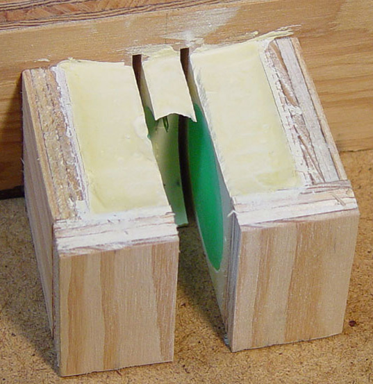
FIGURE 17. Making the bounce pad.
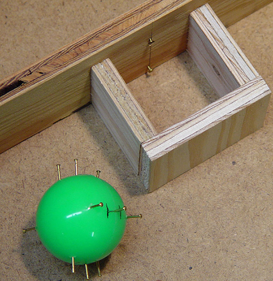
The bounce pad is made from a slice out of the center of a Superball. The ball is made of some of the bounciest stuff invented by man, and they call it Zectron. Dr. Seuss couldn’t have picked a better name. I embedded the ball in plaster inside a small wooden box. Brass nails stick out of the ball in areas that will avoid the path of the saw. The plaster grips the nails, which hold on to the ball as it is cut. The box, plaster, and ball are all cut together into slices with a table saw. When the pieces are disassembled, a nice 7/16” thick pad of Zectron is what remains. The pad is mounted on a 1/2” thick disk of steel plate. Thinner steel does not work so well, as the heavy mass of the steel is needed under the Superball for a good bounce. The steel disk rests on machine screws that fit loosely into holes in the underside of the disk. These screws can be adjusted to “aim” the plate and direct the bounced ball into the basket. Another machine screw is threaded into the bottom of the disk to hold it down. A plastic rim circling the pad is screwed to the steel disk and holds the pad in place, assisted by epoxy glue.
Metalworking
One of the useful tools for the mechanical parts is a lathe. I used a small and relatively inexpensive Sherline lathe, which did the job well. One thing the lathe can do is drill a hole into the center of a turning piece. If the work turns and the drill holds still, the drill automatically wants to go into the center. The lathe can accurately enlarge holes in gears or sprockets to accommodate a shaft. Bushings can be made to make a large hole fit on a small shaft. Freehand turning of insect parts, pulleys, or the important plumb bob is enjoyable.
Almost everywhere there is a rotating part, I used ball bearings. A pulley is made so that the inside diameter of the pulley is .001” smaller than the outside diameter of the bearing. The two are pressed together, and they stay together. A lathe will also cut brass tubing precisely, so that spacers and bushings can be made. Several sizes of telescoping brass tubing came in handy for making everything fit together. A center drill is perfect for starting holes. It is a tiny, short drill on the end of a much thicker shaft. This keeps the point from bending to the side, and allows for accurate hole positioning. With a center drill, a drill press, and decent eyesight it is possible to get holes within .006” of where you want them.
The bugs were made of copper and brass. Sheet copper can be worked by annealing — heating it red hot and then quenching it in water. It is worked by pounding it with a rubber mallet over a metal or wood form, or a metal hammer against a plastic or rubber form. As the copper is worked, it gets work hardened. Anneal it again, and then work it some more. It sometimes takes 8-10 times of annealing and working it to get to the shape you want. Brass is annealed by heating it red hot, and then allowing it to cool slowly on the bench. When the shaping is done, the piece can be pickled for five minutes in a 10% solution of sulfuric acid to remove the oxidation. Fine steel wool gives a nice appearance after that. Pumice on a wet rag wheel gives another nice finish, and Tripoli metal polish on a dry rag wheel will make it very shiny. Gold rouge will make it into a mirror finish.
The pieces are soldered using 96/4 tin/silver “silver bearing solder.” It comes from the hardware store in thick wire form. I pound it flat with a clean hammer against clean steel, and then cut it in half lengthwise with tin snips. Cut it and split it again until there are pieces 1/4, 1/8, and 1/16 the size of the original wire. The pieces to be soldered are cleaned with fine steel wool and painted liberally with “LA-CO Regular Soldering Flux Paste” — the stuff plumbers use. After the pieces are clamped or held into place, the solder is cut into tiny pieces and set right next to the joint to be soldered.
The trick is to heat the pieces to be soldered with a propane torch, without allowing the torch to directly heat the solder or the flux. The flux burns at only a slightly higher temperature than the solder melts. If the piece is heated too long or too hot, or the flame spends too much time on the flux, then the flux will burn. Heat the work slowly, moving the flame so that everything heats evenly. Sometimes you touch just the very edge of the side of the flame to the work. When everything is hot enough, the solder melts and flows right into the joint. If the flux burns and turns brown or black, the solder will never flow. The only solution is to take it all apart, clean it again, and start over. If the flame is too big to heat the pieces without getting the flame on the joint, then a smaller flame is needed. There are some refillable butane torches that have a very tiny flame.
Heat shielding compound is reusable clay that can hold a soldered part in place while you solder another part right next to it. It can also be used to hold parts in position for soldering. As it heats up, it gets hard, and also keeps too much heat from getting to the parts that it protects. When done, spray it with some distilled water and put it in a jar, and it can later be used over and over.
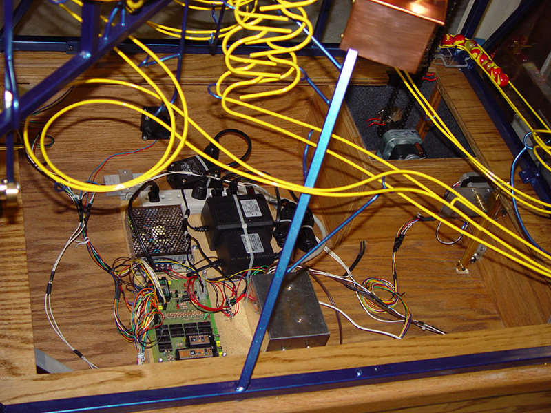
FIGURE 18. Inside of the base.
Why RBS?
This was a truly fun project to build. Getting each stage working was a challenge, and was satisfying to see it work the way I wanted it to. In a public place, people love to watch these kinetic art machines, and sometimes there are crowds that can accumulate. I heard complaints that sometimes a person could not get close enough to see what was happening. “The Flying Marbellos” won “Overall Best of Show” at the Solano, CA County Fair. It is currently on display in my office waiting room, along with my musical water fountain “H-2-Opus”. NV
About the Author
Victor Chaney is a dentist in Vallejo, CA. His website at www.chaneyproductions.com has videos, more pictures, drawings, and Stamp code.