If you really want to know what makes any wireless application work, it is the antenna. Most people working with wireless — radio to those of you who prefer that term — tend to take antennas for granted. It is just something you have to add on to a wireless application at the last minute. Well, boy, do I have news for you. Without a good antenna, radio just doesn’t work too well. In this age of store/online-bought shortwave receivers, scanners, and amateur radio transceivers, your main job in getting your money’s worth out of these high-ticket purchases is to invest a little bit more and put up a really good antenna. In this article, I want to summarize some of the most common types and make you aware of what an antenna really is and how it works.
Transducer to the Ether
In every wireless application, there is a transmitter and a receiver. They communicate via free space or what is often called the ether. At the transmitter, a radio signal is developed and then amplified to a specific power level. Then it is connected to an antenna. The antenna is the physical “thing” that converts the voltage from the transmitter into a radio signal. The radio signal is launched from the antenna toward the receiver.
A radio signal is the combination of a magnetic field and an electric field. Recall that a magnetic field is generated any time a current flows in a conductor. It is that invisible force field that can attract metal objects and cause compass needles to move. An electric field is another type of invisible force field that appears between conductors across which a voltage is applied. You have experienced an electric field if you have ever built up a charge by shuffling your feet across a carpet then touching something metal ... zaaapp. A charged capacitor encloses an electric field between its plates.
Anyway, a radio wave is just a combination of the electric and magnetic fields at a right angle to one another. We call this an electromagnetic wave. This is what the antenna produces. It translates the voltage of the signal to be transmitted into these fields. The pair of fields are launched into space by the antenna, at which time they propagate at the speed of light through space (300,000,000 meters per second or about 186,000 miles per second). The two fields hang together and in effect, support and regenerate one another along the way.
This strange relationship was proved mathematically by physicist James Clerk Maxwell in the late 19th century. Therefore, we call these Maxwell’s equations and they are at the heart of all wireless systems. The radio wave then passes by the receiving antenna and induces a voltage into it that contains all of the originally transmitted signal. The receiver then amplifies this voltage and recovers the information.
So, in summary, an antenna is a transducer for converting a voltage into a radio wave and then converting the radio wave back into the voltage. Any antenna will work just as well at sending as it does at receiving, and you will hear this referred to as antenna reciprocity. Also, let’s get this straight right now: If you do not have an antenna, you won’t have any wireless communications. Even a bad antenna is better than none at all.
Those who really appreciate what antennas do are those people who had to fool around with TV antennas back before cable (BC). No antenna, no TV. If you were lucky enough to be near a TV station, you could use the epitome of all antennas — rabbit ears. Don’t you remember how you had to rotate them, adjust their length, and even attach aluminum foil to them to get a good picture? It was even more of a big deal if you had to have an outside antenna. You had to adjust the direction of the antenna to get the best reception. You discovered the basic rule of antennas used for high frequencies: the taller, the better.
If you are a ham, I won’t belabor the point. You know darn well that most of your experimentation as a ham has probably been with antennas. You have to have one even if your equipment is totally store-bought or home brew. It is a never-ending battle.
For you shortwave listeners, antennas are also critical. Although you can often get by with short inside antennas if you have a good receiver for just listening. If you have ever tried an outside antenna, you know that the longer and higher it is, the better the reception. If you are into scanners, you know that an outside antenna up high is the ticket to maximum coverage.
Today, most of the antennas we encounter are built-in. We have car antennas, cell phone antennas, and those in family radios and CBs. If you use any wireless networking products — like Wi-Fi in a laptop — the antennas are built in, but are just as important. And just try to get a good satellite TV signal without a dish antenna pointed in the right direction. Anyway — and pardon the pun — you get the picture. That seemingly worthless collection of wires, conductors, and copper patterns are the key to good communications.
Antenna Basics 101
Most antennas are some variation of the basic antenna that we call a dipole. A dipole is a pair of conductors that, together, are a half-wavelength long at the operating frequency (see Figure 1).
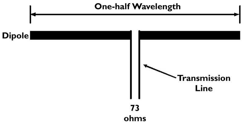
FIGURE 1. A dipole is a pair of conductors that, together, are a half-wavelength long at the operating frequency.
A wavelength is the distance between adjacent peaks or troughs of the radio wave fields. This distance is dependent upon the frequency of the signal. You can calculate wavelength represented by the lowercase Greek lambda — λ — with this formula:
λ = 300,000,000/f
The 300,000,000 is the speed of light in meters and f is the operating frequency in Hz. Since our antennas are mostly used at the higher frequencies, we can use the formula:
λ = 300/fMHz
The wavelength is in meters. For example, a 150 MHz signal’s wavelength is:
λ = 300/150 = 2 meters
You can also calculate wavelength in feet using the formula:
λ = 984/fMHz
The dipole has a length of one-half wavelength, or l/2. This length for wire antennas is computed with the formula:
λ/2 = 492/fMHz
However, if the antenna is wire or some other thin conductor, this has to be modified to:
λ/2 = 468/fMHz
Let’s say you want an antenna to receive the WWV time signal at 10 MHz. A dipole for that frequency will be: λ/2 = 468/fMHz = 468/10 = 46.8 feet
Each section of the dipole then is one-half that length or 46.8/2 = 23.4 feet or about 23 feet and five inches.
This antenna will be resonant to 10 MHz. It acts just like a resonant inductance-capacitance-resistance (LCR) circuit. At the operating frequency, it appears to be a resistance of about 73 ohms. It does have a certain amount of bandwidth, but — if you stray too far from the resonant point — the antenna begins to look like complex impedance that is a combination of resistance and reactance, capacitive at lower frequencies and inductive at the higher frequencies.
You also need some way to connect the antenna to the receiver or transmitter. This is done with a transmission line. The most widely used type of transmission line is coax cable. You can get a coax cable with a 75-ohm characteristic impedance that is a very close match to the antenna’s impedance. RG-59/U is one example, as is RG-6/U, which is commonly used in cable TV systems.
As it turns out, most people use a 50-ohm coax with a dipole because it is the most common impedance used for inputs and outputs on receivers and transmitters. There are lots of different types of 50-ohm cable, like RG-58/U, RG-8/U, and RG-213/U. There are many others. Even with the difference between 50 and 75 ohms, this mismatch doesn’t matter that much. As it turns out, the impedance of the dipole at resonance varies considerably with the height above the ground. The 73-ohm value doesn’t really become the actual impedance until the antenna is over one wavelength above the ground. This is pretty high at the lower frequencies and is rarely attained. That is why the antenna is such a good match to the common and cheap 50-ohm cable.
The dipole is actually a directive antenna. That is, it does not radiate the electromagnetic waves equally in all directions. The radiation pattern is actually a figure-eight pattern, as shown in Figure 2.
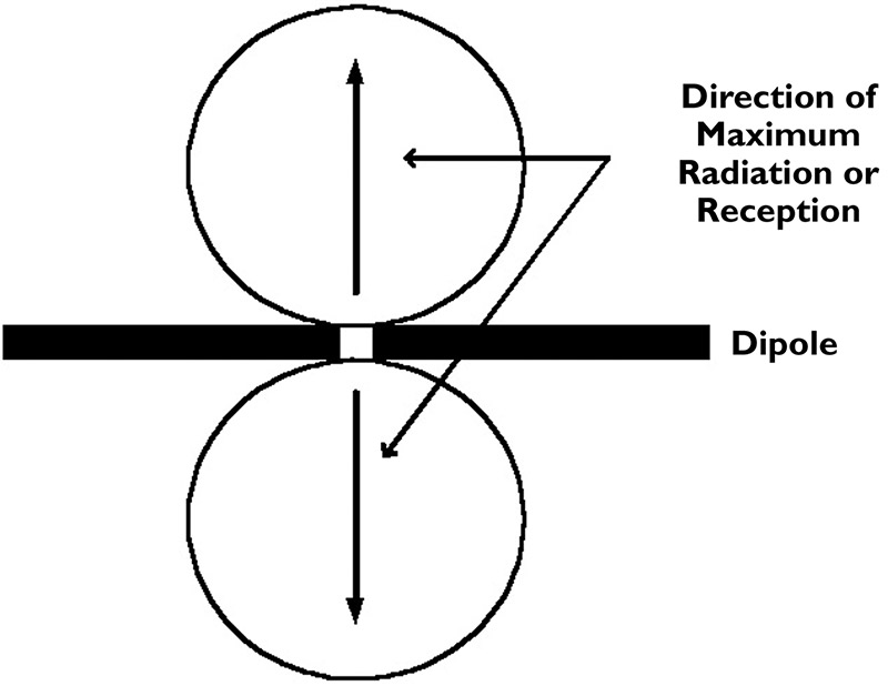
FIGURE 2. The radiation pattern is actually a figure-eight pattern.
Looking down on the antenna from above, the maximum horizontal radiation pattern is at a right angle to the line of the antenna wire. If you can think in 3-D for a minute, visualize that figure eight as a doughnut-shaped pattern. Looking at the pattern, there is actually very little radiation from the ends of the antenna. Now you can see why it is important to orient the antenna for the desired direction of transmitting or receiving.
Incidentally, if you mount the antenna vertically, its antenna pattern is a circle. We call this omnidirectional. It radiates or receives equally well in all directions. This is a pretty tricky thing to do physically with long wire antennas, so this technique only works for short antennas used at high frequencies.
That brings up one more key antenna fundamental: polarization. Polarization is defined as the direction of the electric field with respect to the Earth. If the dipole is mounted horizontally, the polarization will be horizontal. Mounting the antenna vertically produces vertical polarization. Ideally, you want both the transmitting and receiving antennas to use the same polarization for maximum signal strength, but, as it turns out, as the wave travels over long distances it is rotated a bit, so you can still get reception of a vertically polarized signal on a horizontal antenna and vise versa.
Another common antenna type is the quarter-wave (λ/4) ground plane (see Figure 3).
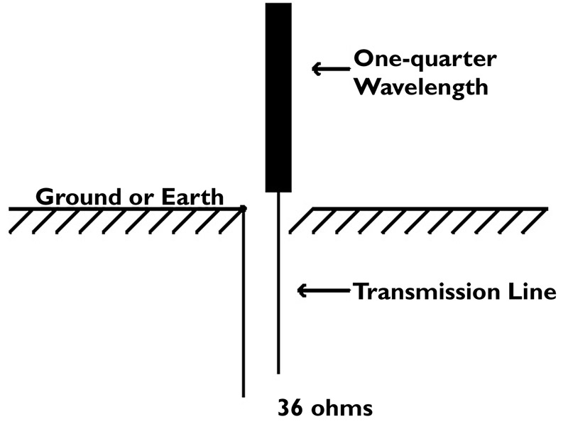
FIGURE 3. Another common antenna type is the quarter-wave (l/4) ground plane.
What it amounts to is half of a dipole, mounted vertically. The center conductor of the coax attaches to this vertical conductor while the shield of the coax connects to ground. The ground (or Earth) acts like the other half of the dipole. The nice thing about a ground plane is that the length of the antenna is half that of the dipole. This is a big deal at the lower frequencies.
For example, the length of a dipole for an AM radio transmitter at 650 kHz (0.65 MHz) will be:
λ/2 = 468/fMHz = 468/0.65 = 720 feet
The actual formula for a quarter wave ground plane is:
λ/4 = 234/fMHz = 234/0.65 = 360 feet
Note, if we use a quarter-wave ground plane, the length is only 360 feet. Think of the cost difference between a 720-foot tower and a 360-foot tower — big difference.
In most applications, the Earth is not used as the other side of the dipole. Instead, at the higher frequencies, we often use a large metal area — larger than one-quarter wavelength. For example, on car antennas, the ground plane is the metal surface of the car surrounding the antenna. In some antennas, an array of radials is used (see Figure 4).
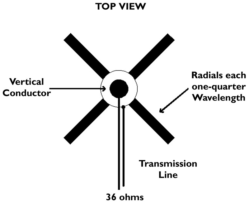
FIGURE 4. In some antennas, an array of radials is used.
Note that there are four or more conductors of l/4 mounted at the base of the vertical segment of the antenna. These may be wires on lower frequency antennas or short horizontal conductors in higher frequency antennas.
In any case, the ground plane antenna is also resonant at its frequency of operation. The resistive value of its feed point is about 36 ohms. Normally, we use a 50-ohm coax cable to feed the ground plane, as it is a close match and works well. The radiation pattern for the ground plane is a circle, meaning that it is omnidirectional and transmits and receives equally well in all directions.
Common Antenna Types
Most radio applications use a dipole or a ground plane, but there are many other special types of antennas. Almost all of them are some variation of either the dipole or the ground plane. A good example is the widely used Yagi. Take a look at Figure 5.
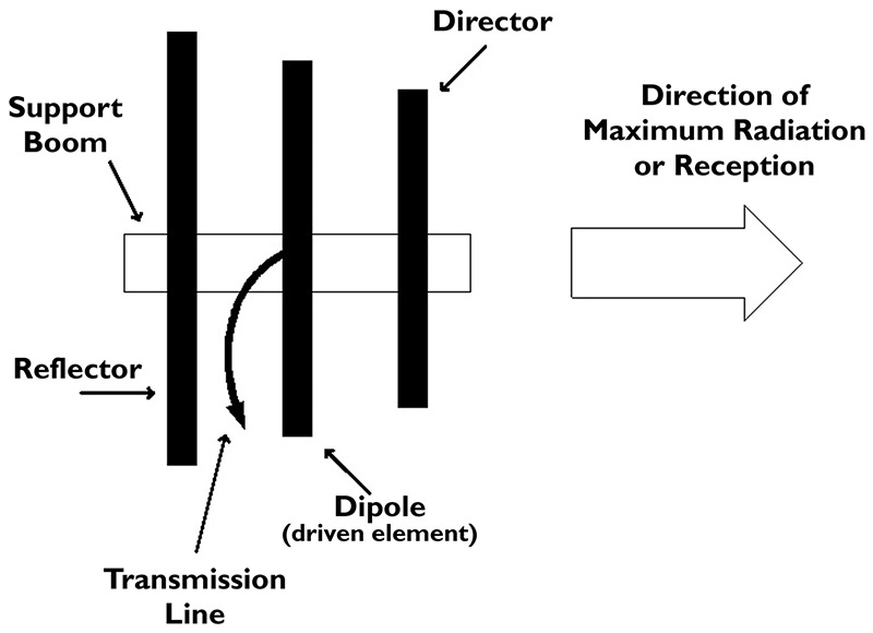
FIGURE 5. The Yagi antenna uses a dipole as the antenna, but parasitic elements are added to shape the radiation pattern.
This antenna uses a dipole as the antenna, but parasitic elements are added to shape the radiation pattern.
The longer element next to the dipole — or driven element — is called the reflector. It actually does reflect (at least redirect) some of the energy from the dipole in the forward direction. The shorter element is called a director. It further helps focus the radio wave in the forward direction. The end result is that the dipole energy is concentrated and directed in one direction, making the antenna directive. The radiation pattern looks something like what you see in Figure 6.
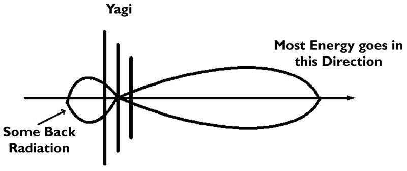
FIGURE 6. The dipole energy of the Yagi is concentrated and directed in one direction, making the antenna directive.
The Yagi antenna has what we call gain. It actually boosts the signal level because the electromagnetic energy is focused in one direction. For example, if your transmitter puts out one watt of power and you connect it to a Yagi, the actual effective radiated power (ERP) may be five times that — five watts. The receiver doesn’t know the difference between a plain old five-watt transmitter on a simple dipole or a one-watt signal from a Yagi. You can actually get much higher gains by adding more directors. Yagis with up to 20 directors are available to give super high gains. The downside is that the antenna is highly directive so you have to point it correctly to get the signal.
Another common type of antenna is the parabolic dish (see Figure 7).
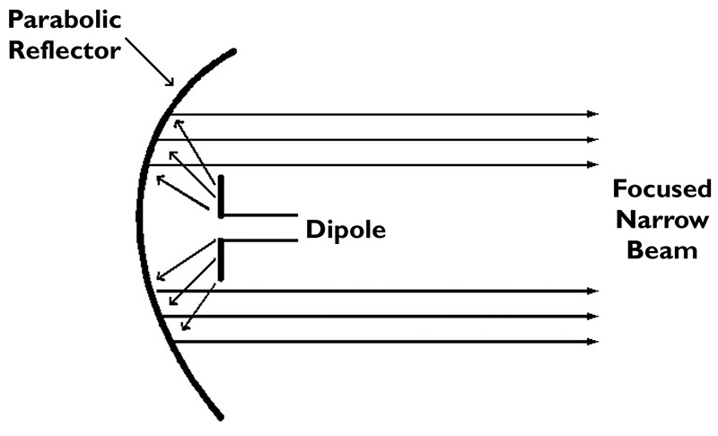
FIGURE 7. Another type of antenna is the parabolic dish similar to any satellite dish system.
It is used mainly at microwave frequencies above 1GHz. The dish, as it is called, has a parabolic shape that takes the energy from an antenna like a dipole and concentrates all its radiation into a highly focused radio beam. The antenna signal reflects off of the dish and, because of its unique geometric shape, all of the waves are concentrated into a very narrow beam. This makes the dish very highly directive, but the upside is the super high gain. You can see why a dish is used on satellite TV. With the satellite out there in orbit 22,300 miles away, the signal is extremely small when it gets to Earth. The dish has a very high gain, so it, in effect, boosts the signal level before it gets to the receiver.
Another type of antenna you don’t see much of, but that is widely used, is the patch antenna. It, too, is used mainly at microwave frequencies. A very common application is with wireless local area networks (WLANs) that connect PCs and laptops. Popular access points, called hot spots, allow laptops to connect to the Internet at many public places, like airports, hotels, and coffee shops. The antenna used in many of these 2.4-GHz radios is a patch. It is essentially just an area of copper on a printed circuit board (PCB) about one-half wavelength in size that may be square or circular (see Figure 8).
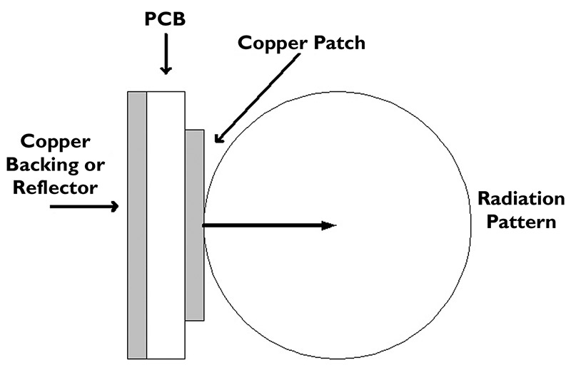
FIGURE 8. The antenna used in many 2.4-GHz radios is just an area of copper on a PCB about one-half wavelength in size.
A copper ground plane on the other side of the PCB acts like a reflector to focus the energy forward.
You can actually put multiple patch antennas on a large PCB and drive all of them simultaneously. This gives lots of gain and directivity. You can even control the phase of the signals to or from the antenna, making it possible to shape the radiation pattern or the gain on the fly. These are called phased arrays and they are widely used in military radar, but they are becoming more popular in cell phone systems and WLANs.
SInce, we're out of space for now. I will follow up in a later column with more antenna types. For now, pay attention to your antenna. It will make your seemingly failed wireless project a true success. NV
To read more on phased array antennas, see How Phased Array Antennas Work.