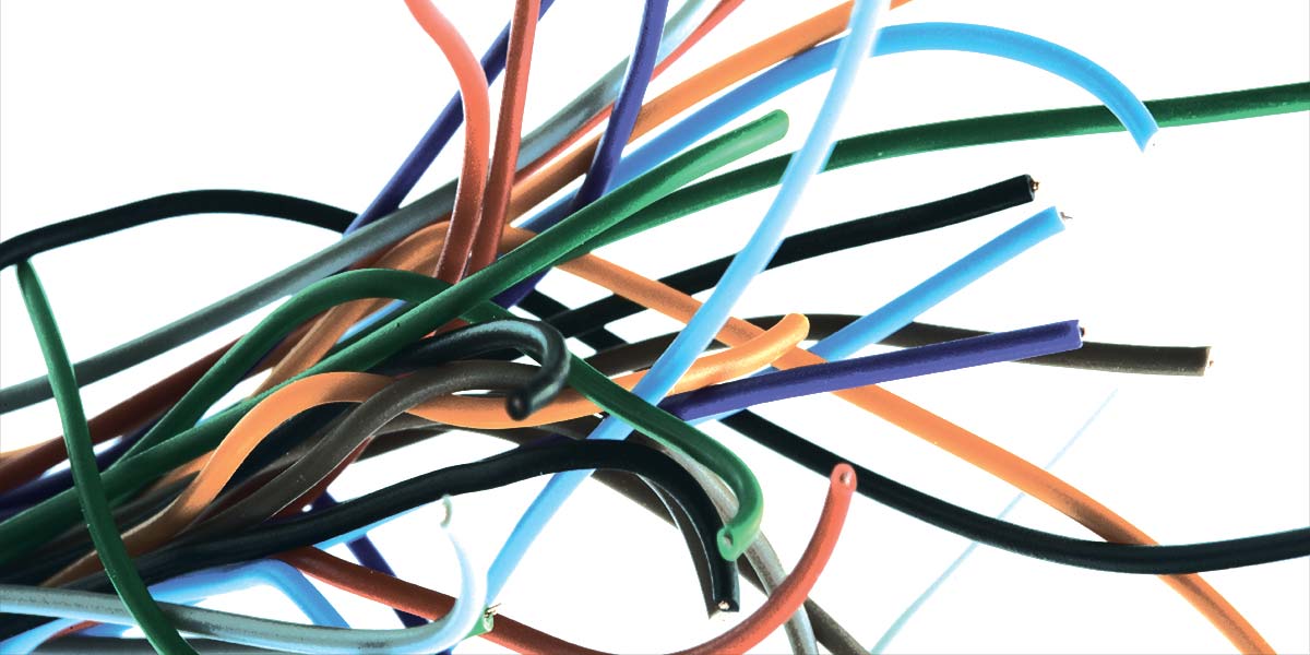
My friend Art, a radio amateur, built a transmitter for operation on the 70 cm band (420-450 MHz), but it didn’t work. There was plenty of RF drive into the final tripler, but the output was very low. Ed, his friend, came over to see the new rig.
“You’re too neat, Art!” commented Ed. “Don’t let my wife hear you say that! Whatever do you mean?” asked Art. “Look at your wiring. It’s all neatly bundled into the corners of the chassis, with nice right-angle bends. That’s okay for the power wiring, but not for the RF lines. Connect them directly by the shortest, straightest route.”
Later that night, Art reworked the RF wiring in his new transmitter and turned it on. The output power was what it should be. “Well I’ll be (expletive deleted)!” Art exclaimed.
Why did right-angle bends in the wires cause such a problem? As explained in this article, wires used in resistors, capacitors, inductors, antennas, and ground connections affect AC and DC signals differently.
ELECTRICAL PROPERTIES OF WIRE
A perfect wire should conduct a signal without adding noise, attenuation, or distortion. Whatever is electrically happening at one end of the wire should be happening at the other end exactly in the same form, no matter what the current, voltage, frequency, surroundings, or temperature. However, this isn’t the case. For example, the effect of the wire on a signal depends on the frequency of the current that the wire is conducting. The higher the frequency, the more the effect of the wire on the signal.
When the current is DC (ƒ = 0, that is, the frequency is 0 Hz), the behavior of the wire is most nearly the perfect behavior described above. The shape does not matter, what is near or around the wire does not matter, and the current flows in the whole wire. But the temperature matters. For example, six feet of No. 12 wire at room temperature (20°C) has a resistance of about 9.5 mΩ (0.0095Ω). At 30°C (hot day), the same wire has a resistance of 9.87 mΩ. When the current is AC (at any frequency), new things begin to appear (the numbers in this next section are summarized in Table 1).
| Conductor Type and Length at 20°C |
DC Resistance |
Resistance
at 30 MHz |
Inductance in Microhenries |
Inductive Reactance
at 30 MHz |
| No. 12 Copper, six feet long |
0.0095 ohms |
0.40 ohms |
2.72 µH |
513 ohms |
| Three Conductors of No. 12 Copper, six feet long |
0.00318 ohms |
0.18 ohms |
(depends on wire surface condition) |
(depends on inductance) |
| No. 6 Copper, six feet long |
0.00237 ohms |
0.20 ohms |
2.0 µH |
377 ohms |
| No. 30 Copper, six feet long |
0.619 ohms |
3.4 ohms |
3.48 µH |
656 ohms |
| Copper Foil, six feet long, one inch wide, five mils thick |
0.0095 ohms |
0.11 ohms |
2.0 µH |
656 ohms |
| Copper Foil, six feet long, two inches wide, five mils thick |
0.00475 ohms |
0.06 ohms |
1.75 µH |
330 ohms |
TABLE 1. Resistance, Inductance, and Reactance.
- Resistance — With AC, there are two kinds of resistance. The first is the ordinary well-known stuff that turns electric power into heat. The second is radiation resistance which turns alternating current into electromagnetic waves. That means that a wire becomes an antenna, which is certainly not an ideal conductor.
- Skin Effect — As the frequency increases, current moves out from the center of the wire, and concentrates at the surface so that, at high frequencies, all the current flows in a thin “skin” at the surface of the wire. To an RF (Radio Frequency) current, a wire looks like a thin tube or pipe.
RF currents could be considered “anti-social;” each RF current element tries to get as far away from every other element as possible. Since the current flows entirely on the surface of the wire, the inside of the wire might as well not be there. At 30 MHz, the effective conducting thickness of a copper wire is a surface skin about 0.5 mils (0.0005 inch) thick. So, a tube of copper half a mil thick and 80.8 mils in diameter is just as good at 30 MHz as a solid No. 12 wire.
Now the result of this skin effect anti-social behavior is that six feet of No. 12 copper wire has a resistance at 30 MHz of 400 mΩ, compared to 9.5 mΩ at DC. Even if the wire connects to a perfect ground at one end, the other end is not a good ground. And there will be about 2.2 µH of inductance, as well.
- Proximity Effect — If more surface area decreases the resistance, it would be reasonable to use more than one wire. Consider the result with three twisted No. 12 conductors six feet long. It would seem that the resistance should be one-third of that produced with one No. 12 conductor (0.4Ω). Instead, the RF resistance is now at least 0.18Ω (instead of one-third of 0.4Ω or 0.133Ω)! It could be a lot more; it depends very much on the condition of the wire surface. The inductance with this arrangement will be higher, too.
The proximity effect is very similar to the skin effect in that it can also be visualized as an anti-social tendency. The RF current will stay on the top surface of the wire so, with twisted wires, the current flows from one conductor to another, and that is a high-resistance path. Incidentally, this is why copper braid has a high RF resistance — up to 1Ω per foot at 20 MHz.
To avoid the proximity effect with twisted wires, use one wire of approximately the same size in circular mils as twisted wires. No. 6 wire has more than three times the cross-sectional area of No. 12 wire. Six feet of No. 6 wire will produce 0.2Ω of RF resistance (only half of the resistance of one No. 12 wire), and about 2.0 µH of inductance at 30 MHz.
Now consider the proximity effect in a coil. RF resistance is lower if the space between turns is equal to twice the wire diameter. Then, the RF resistance increases by only about 5%, whereas if the turns are tightly pressed against each other, the resistance increases by about 33%, avoiding the wire surface that is pressed against another wire surface. This is true if the current is flowing in the same direction in the closely spaced wires; if the current in adjacent turns were somehow flowing in opposite directions, the resistance increase would be much greater.
- Lazy Effect — The numbers shown in Table 1 apply to straight wires. If they are curved or wound into a coil, the resistance rises because the RF current takes the shortest route, which is the side of the wire nearest the center of the coil. Taking only the inner surface of the wire around the coil reduces the amount of copper for conduction.
- Reactance and Impedance — These are forms of opposition only to the flow of AC current because they are dependent upon the frequency (see the sidebar Calculating Reactance and Impedance). Inductive reactance increases and capacitive reactance decreases as frequency rises. Impedance is a combination of resistance and reactance.
CALCULATING REACTANCE AND IMPEDANCE
WIRES AT RADIO FREQUENCIES
By reason of the skin effect, a solid copper wire looks like a very thin tube of resistive material to RF current at 30 MHz. And, since there is inductance, we can think of the wire not as straight but as a coil. See Table 1 for the characteristics of different sizes and shapes of wire at 30 MHz.
Now consider capacitance. A capacitor is formed wherever there are two conductors separated by an insulator. Think of two small spots on our thin-tube-of-resistive-material coil. There is air between these two surfaces which insulates them, and thus forms a capacitor! Well yes, but doesn’t the conductor itself short these two surfaces together? Not quite. There is inductance and resistance between any two spots on the surface of our conductor. Now think of the whole surface of the conductor as separate spots, insulated from each other, and forming capacitors.
The net result for our 30 MHz RF current is a very thin tube of resistive material in the shape of a coil, bristling with capacitors all over the surface. If you are thinking of the inductance and capacitance in a single piece of wire producing a resonant circuit, you’re absolutely right.
Considering the effects described above, at least three things can be done to minimize RF resistance:
- Make the surface area as great as possible. The thickness of the conductor is almost irrelevant.
- The conductor should be as nearly straight as possible. That means that “neat” wiring or circuit board layout (nice sharp bends) increases RF resistance.
- Conductors of RF currents should be kept apart, especially if the currents are flowing in opposite directions.
INDUCTIVE CARROTS?
Inductive reactance and capacitive reactance are opposite: what one does, the other one does “upside down.” Inductive reactance increases in direct proportion to the frequency; capacitive reactance decreases in inverse proportion to the frequency. And, they cancel each other. If you have equal quantities of inductive and capacitive reactance in series, you have nothing left but a little bit of resistance. This is called resonance.
In a resistance, the voltage and current are in phase. That is, when the voltage is at a positive peak, the current is also at a positive peak.
With pure inductive reactance, when the voltage is at a positive peak, the current is at zero! That means that the current lags the voltage by up to 90°.
In a pure capacitive reactance, when the current is at a positive peak, the voltage is at zero! That means that the current leads the voltage by up to 90°.
I found this a difficult concept, but there is an easy way to demonstrate it. Read the sidebar “Seeing Is Believing.”
ANYTHING that behaves with the characteristics shown in the comparison table (see the “Kinds of Opposition” sidebar) is a resistor, inductor, or capacitor.
KINDS OF OPPOSITION
Making electronic circuits work correctly is a matter of making electrons go where they should and when. Controlling electron flow with “opposition” devices is a way to do that.
There are four kinds of opposition: resistance, inductive reactance, capacitive reactance, and impedance. Each is measured in ohms and Ohm’s Law applies to all calculations with these effects. Here is a comparison of all four, and their respective behaviors:
| Type Of Opposition To Current Flow |
Produced By |
Measured In |
Relationship Of Voltage And Current |
Behavior With Frequency |
| Resistance |
Resistors |
Ohms |
In phase |
Same at all frequencies |
| Inductive Reactance |
Inductors: Coils and Wires |
Ohms |
Current lags voltage by up to 90º |
Increases linearly with frequency |
| Capacitive Reactance |
Capacitors: Any two conductors separated by an insulator. |
Ohms |
Current leads voltage by up to 90º |
Decreases as the reciprocal of frequency |
| Impedance |
Two, or all three of the above, in series or parallel combinations |
Ohms |
Depends on proportions of reactance and resistance. |
Can increase or decrease linearly or as the reciprocal of frequency |
CIRCUIT BOARD TRACES
According to Table 1, the type of conductor with the lowest resistance and inductance is copper foil. Where is there a large surface of copper foil? Well, a copper-clad circuit board is most familiar. The copper forms what is called a ground plane — a very good term in this application.
Some circuit boards are copper-clad on both sides, with non-clad areas only where there are parts-mounting pads and connection traces. But, all of the copper foil that is not a connection trace is grounded. Circuit boards that have high-frequency signals or high-speed data — and therefore require very good grounds — are sometimes made with a copper foil surface on both sides with the connection traces on an internal layer. This arrangement illustrates the importance of a large surface area for a good ground, that is, very low resistance and inductance.
A double-copper-clad circuit board with conducting traces between the two ground plane surfaces suffers from the proximity effect, capacitance to ground, and inductance in the traces. Circuit board traces have approximately 10 nH per centimeter of inductance (1,000 nH = 1 µH) and, with the capacitance of the ground plane, the traces can form a low-pass filter which will produce a falling frequency response, different time delays for different frequencies, and can produce ringing. As a result, data pulses will be rounded and timing may be wrong.
Circuit boards operating at frequencies greater than 1,000 MHz (this includes high-speed data) must use a different arrangement: a transmission line. Transmission lines have a characteristic impedance (Zo) which is determined by the size and shape of the conductors and the thickness and type of material of the insulator between. A common transmission line is co-axial cable, such as RG-58, which has a characteristic impedance of 50Ω.
What is characteristic impedance? You do not measure it with an ohmmeter. If a transmission line, no matter how long, is terminated in its characteristic impedance, the other end will look like the characteristic impedance to RF currents. It will be a pure resistance if the termination is the correct, pure resistance. This is a very good arrangement because the inductance and capacitance no longer affect the frequency response.
PRACTICAL APPLICATION
The most dramatic experience with wires that don’t behave as wires that I have ever experienced happened about a year ago with an instrument called a vector voltmeter. Figure 1 shows the front panel. It’s a wonderful old Hewlett-Packard instrument; it can tell you things about a circuit that a ‘scope cannot. On my workbench, it is indispensable, and now it is irreplaceable since it is about 35 years old.
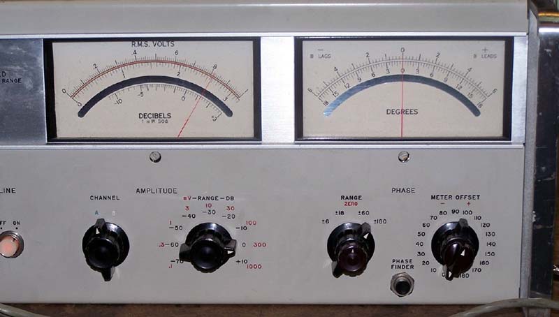
FIGURE 1. Hewlett-Packard Type 8405A: Vector Voltmeter, Front Panel
So, when it stopped working correctly, I had to fix it. It has an indicator on the front panel marked “APC unlocked” (Automatic Phase Control; similar to a phase-locked loop). When the APC is unlocked, the input signal (up to 1 GHz) and the internal phase-locked loop are out of synchronization. An internal phase comparator has to pull an internal oscillator to the correct frequency and phase, and keep it there even in the presence of frequency modulation. That’s a very demanding operation!
It was getting harder and harder to lock the APC until, after a few weeks, it wouldn’t lock at all. Without a perfect phase lock, the instrument is useless.
Signal sampling up to 1 GHz is accomplished with a 300 ps (3 x 10⁻¹⁰ second) pulse, adjusted to frequencies between 0.98 MHz and 2.0 MHz, producing a signal for measurement of 20 kHz. Such a short pulse contains energy at 3 GHz. The pulses are produced on a circuit board in a shielded cage with sliding ground clips on the sides to contact the copper-clad circuit board. There were also ground wires on the edge connector. Producing a signal at such frequencies — and with such very precise and critical frequency and phase control — requires a very good ground. I suspected that the ground connections to the circuit board had somehow deteriorated over time.
Assuming 10 nh/cm (nanohenries per centimeter) of wire length, and four wires of about 2 cm length in parallel, the inductance would be about 5 nh and, at 3 GHz, the inductive reactance is about 90 ohms. What the reactance of the slide clips was, I couldn’t possibly guess.
After making measurements, testing, viewing waveforms, replacing parts, making theological and biological comments in four letters, scratching my head and almost making a hole, somehow I decided to add some more ground wires to the pulse generator edge connector. They are the green wires in Figure 2. It worked perfectly!
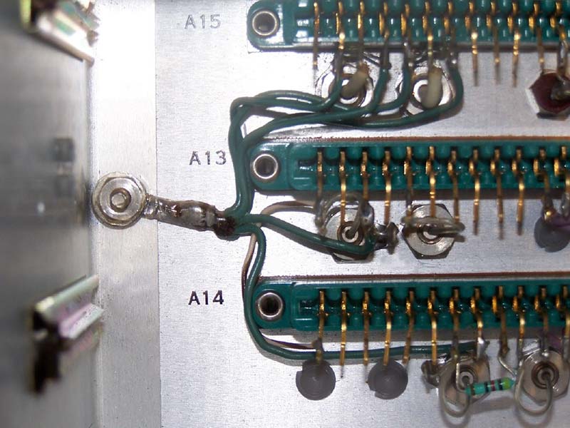
FIGURE 2. Hewlett-Packard Type 8405A: Vector Voltmeter Pulse Generator, showing modification for lower ground impedance (green wires) which restored the instrument to working condition.
I can only assume that, over the years, the circuit board grounding slide clips corroded, the ground impedance rose, which caused the APC to fail. The extra ground wires were each in parallel with the existing ground circuit, lowering the ground impedance and reducing interaction with other circuits. That’s what can happen when a wire acts like an inductor and a resistor! NV
SEEING IS BELIEVING
You can see the current waveform leading the voltage waveform in a capacitive reactance with a simple setup:
- The parts required are a 0.1 µF capacitor and a 1.0 Ω resistor. The values can be approximate.
- Connect the capacitor and resistor in series.
- Connect a signal generator output to the capacitor free end and ground to the resistor free end. The generator should be able to provide about 1.5V RMS at 30 kHz into a 50 Ω load.
- Connect a dual-trace ‘scope so that the generator output can be seen on Channel 1, and the voltage across the 1.0 Ω resistor on Channel 2.
- Adjust the scope’s vertical sensitivity so that both traces cover the graticule vertically.
- Adjust the scope’s horizontal sweep so that both traces show about one cycle and, with the generator output turned off, the traces are on the center horizontal line of the graticule. If there is DC in the generator output (the Channel 1 trace moves vertically as you adjust the generator output), switch the ‘scope inputs to “AC coupling.”
- You will see the Channel 2 trace is to the left (leading) of the Channel 1 trace by about one-quarter of a cycle, or about 90°.
The Channel 2 trace from the 1Ω resistor is showing the current waveform through the capacitor. The capacitive reactance of the capacitor at 30 kHz is about 50 ohms, so the 1Ω resistor, being so much smaller, does not change the phase relationship significantly.
If the capacitor were replaced by an inductor of about 265 µH (inductive reactance of about 50 ohms at 30 kHz), the Channel 2 trace (current) would be to the right (lagging) of the Channel 1 trace by about a quarter of a cycle.
This is a hard concept: voltage and current in phase in a resistance, current leading the voltage by 90° in a capacitance, and current lagging the voltage by 90° in an inductance. It is the convention to refer phase shift to the voltage waveform, that is, the voltage waveform is considered to be at 0°. Then, if the current is ahead of the voltage (leading), it is considered to be at a positive angle; if the current waveform is behind the voltage waveform (lagging) it is considered to be at a negative angle.
I have found it easier, in a series circuit, to think of the current waveform as a reference, and then to think of the voltage waveform as a result of the effect of the resistance or reactance (or combination) on the current. But then, before any calculations, it is necessary to readjust the observation to conform with the convention (voltage at 0°).
REFERENCES
(1) B. Whitfield Griffith, Jr. Radio-Electronic Transmission Fundamentals, 2000, ISBN 1-884932-13-4. Available from the Amateur Radio Relay League, www.arrl.org/qex/. ARRL Order Number: RETF; $75 plus shipping and handling. Order toll-free: 1-888-277-5289 or QUICK ORDER online.
(2) Dr. F. E. Terman, Radio Engineer’s Handbook, First Edition: 1943, Section 2: “Circuit Elements,” pp. 26-53. McGraw-Hill Book Company.
(3) Other books by Dr. Terman:
Electronic and Radio Engineering, 1955
Fundamentals of Radio, 1938
Electronic Measurements, 1952
If you can find these books anywhere, and can afford them, grab them; you’ll never regret it.
These books are worth any couple dozen others that I can think of. Dr. Terman was a great teacher; perhaps the greatest electronics teacher ever. The Griffith text guided me through an AM broadcast transmitter installation. I cannot recommend these books too highly.