Efforts to design and construct devices for supplying renewable energy surprisingly began almost 200 years ago, ironically, at the very height of the Industrial Revolution, which was largely founded on the promise of seemingly inexhaustible supplies of fossil fuels. Contrary to the prevailing opinion of the day, a number of engineers questioned the practice of an industrial economy based on nonrenewable energy and worried about what the world's nations would do after exhausting the fuel supply.
Using Solar Cells On Small Projects Is A Bright Idea!
The earliest known record of the direct conversion of solar radiation into mechanical power belongs to Auguste Mouchout, a mathematics instructor at the Lyce de Tours. Mouchout began his solar work in 1860 after expressing concerns about his country's dependence on coal. “It would be prudent and wise not to fall asleep regarding this quasi-security,” he wrote. “Eventually industry will no longer find … the resources to satisfy its prodigious expansion. What will industry do then?” By the following year, he was granted the first patent for a motor running on solar power and continued to improve his design until about 1880. During this period the inventor laid the foundation for our modern understanding of converting solar radiation into other forms of power.
Where Mouchout left off, a French man by the name of Charles Tellier took over in 1885. Considered by many the father of refrigeration, Tellier actually began his work in refrigeration as a result of his solar experimentation, which led to the design of the first nonconcentrating, or non-reflecting, solar motor.
If you’re concerned about your ever-growing battery bill, you might want to consider using solar power. Although solar cells are not usually as straightforward as batteries, once you get used to their characteristics, they’re easy.
Types of Solar Cells
A solar cell (sometimes called a photovoltaic cell) is basically a large diode. Just as a photodiode (or even, for that matter, a regular glass-walled diode like a 1N914) will produce a voltage when exposed to light, so will a solar cell. The difference is that a solar cell is designed to produce a useful current. Most solar cells, like most diodes, are made from silicon. A few other semiconductors can be used, such as gallium arsenide, but these are found only in very special circumstances, such as satellites that might need to endure large amounts of radiation in space that would damage silicon cells. Copper oxides can be made to act as solar cells, too (and were the first type of cell discovered), but they are very inefficient.
There are basically two types of silicon cells — crystalline and amorphous. Crystalline cells are made from thin wafers of nearly pure silicon, just like those used to make silicon chips (for that reason, they are often circular or curved, having been cut from circular wafers). They are rigid, but light and fragile, and are fairly expensive to make. Rather cheaper are amorphous cells, which are made from silicon deposited onto a substrate. This can be glass, as in the Sunceram cells by Panasonic that are used in many small solar robot projects, or a flexible plastic film, such as the Powerfilm cells by Iowa Solar Films. These thin plastic cells can be very lightweight and can be bent around various shapes. For outdoor applications, these are available in an ultraviolet resistant Tefzel plastic coating, though this makes the cells heavier and more expensive.
Because a cell is just a diode, it produces a voltage that is nearly a constant, related to the electronic bandgap of the material. For silicon, this is about 0.6 volts. This is obviously inconveniently low, so it is usual to array cells in series (a “string” of cells) to yield a useful voltage. One way is, of course, to solder or clip together lots of individual cells, but this can be tedious and delicate. Many modern amorphous cells, where the silicon is painted onto a substrate, are basically painted on as several individual cells connected in a series, making a much more convenient solution. Such mini-arrays are available with outputs from three to 15 volts.
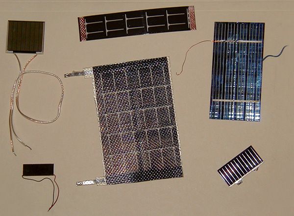
Clockwise from top left are various types of solar cells: a Sunceram five-volt cell from Solarbotics, a TX 3-25 thin film plastic Powerfilm three-volt module from Iowa Thin Films, a large crystalline silicon cell (0.6 volt) from a grab bag, a smaller silicon cell (0.6 volt), a larger three-volt Powerfilm module — this one encapsulated in an ultraviolet-resistant Tefzel sheet, and a small Sunceram module taken from a defunct calculator.
Peak-Power Tracking
A solar cell’s output characteristic (the I/V curve) for given light conditions is usually fixed by two numbers: the open-circuit voltage and the short-circuit current. These are what you read if you just put a high-impedance voltmeter across the cell or a low-impedance ammeter, respectively. The open-circuit voltage for individual silicon cells is always about 0.6 volts. It depends only very slightly on light levels, but will depend on temperature being a little higher under cold conditions. (Solar cells on satellites also need to worry about the characteristic being affected by radiation in space, but, unless you are unhealthily close to a nuclear reactor, you shouldn’t need to worry about this.)
The short-circuit current is directly proportional to the light level and is basically set by the area of the cell. (More area means more photons of light collected, and more photons mean more charge carriers and more current.)
However, neither of these test conditions is useful. The power provided by the cell is voltage x current, so the short- and open-circuit tests give no power.
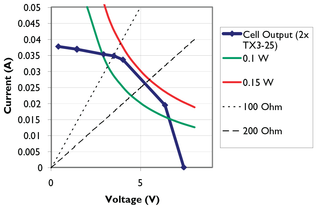
Solar cell output characteristic (I/V curve). The blue line is the output of two Powerfilm TX 3-25 modules in series. The short-circuit current is about 37 mA and the open circuit voltage about 7.5 volts. Peak power of about 0.15 watts (red line) occurs for an output of about five volts and 25 mA. Operation at three or 6.5 volts will reduce the output to about 0.1 watts (green line). Peak-power conditions correspond to a load impedance of about 200 ohms.
Domestic power plants and satellite power systems use feedback control circuits to track this peak-power point (which depends on temperature, light levels, radiation dose, and so on). However, for simple robots and other projects, it is usually adequate to assume that peak power will be roughly three-quarters of the open-circuit output and design the circuit to operate fixed at that point. Still, before finalizing a circuit, it’s a good idea to measure the output characteristic of the cells you’re using by putting different load resistors across it and measuring the voltage. The output power is just the load resistance multiplied by the square of the voltage across it.
One useful IC for small solar power supplies is the ICL7660 voltage converter, which rapidly charges a capacitor with the supply, then switches over to charge another, and then back to the first before it has time to substantially discharge. These two capacitors are wired so that their voltages can be summed together to give almost double the input. The device can handle input voltages from 1.5 to 10 volts. Maxim makes higher current versions; the MAX 860 and 660 are able to handle up to around 100 mA.
Light Levels
Sunlight at noon on a clear day dumps about 1,300 watts of power per square meter. A 10-cm2 cell, therefore, intercepts about 13 watts of sunlight, but only a fraction of this can be converted into electricity. Even the most efficient (and expensive) multiple-junction cells on satellites convert only about 20 percent of this into power. For the amorphous cells in most small electronics applications, the efficiency is only about five percent. The crystalline silicon cells used for most domestic power systems are typically about 10 percent efficient, so we can only get about one watt out of a 10 x 10-cm2 cell.
Note, however, that we will have much less power available in dim, indoor conditions. Our eyes are very adaptable, so we can see over a wide range of light levels (full moonlight has a million times less light per unit area than full sunlight), but a solar cell’s short-circuit current (and therefore power at peak-power conditions) will be proportional to the light intensity. Consider the floor of a six-meter-wide room lit by a 100-watt light bulb. Even if the walls and ceiling were perfect mirrors, a robot on the floor is only going to receive about three watts per square meter. A 10 x 10-cm cell and five percent conversion efficiency would only produce about 1.5 milliwatts of electricity.
Devices for indoor operation and devices with very small solar cells must, therefore, either have microwatt power levels (calculators are one example) or must trickle-charge an energy store and operate only periodically. This is the “solar engine” circuit used in many BEAM projects: A capacitor is trickle-charged, essentially starting out by charging with the high short-circuit current from the cell, then trailing off as the capacitor charges up. Eventually, it will almost reach the open-circuit voltage of the cell, only drawing enough current from the cell to balance any leakage. However, a threshold switching circuit, using a flashing LED or a 138 voltage switch, will instead discharge the capacitor when the voltage has reached a useable level.
An Example — Solar Power With Current Monitoring
One project I have recently begun is a Tumbleweed rover, a windblown sphere that can traverse a long distance by rolling in the wind without using motors to drive it. Such a vehicle has been proposed for exploring Mars and one was recently tested in Antarctica. I wanted to explore how a lightweight, solar-powered version could be made by attaching flexible solar cells to the wall of a beachball, using a Basic X-24 microcontroller to measure its motion with an accelerometer.
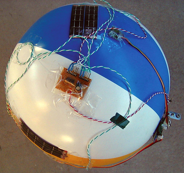
A Tumbleweed rover made from a beachball and thin-film solar cells (top and bottom) with a circuit board carrying diodes, etc. in the center. Another small board with a microcontroller is at right. By distributing the components around the ball, it rolls more evenly.
Because a solar-power-only rover could have its power interrupted by shadows, I used a small battery for short-term operation, which would then be topped off by the solar panels. Driving the microcontroller required 25 mA or so at six volts or more, so I used a set of three tiny nickel metal hydrite (NiMH) batteries, each with two cells. These were so small that they could be distributed around the perimeter of the beachball. Pin 24 (Vin) of the BX-24 was connected to the batteries (Vout) via a switch. You might get away with a smaller battery, wiring four cells to get 4.8 volts to the Vss supply on the BX-24, but this would be much less tolerant of voltage drops as the battery discharged. Also, if you don’t need the speed, memory, or A/D converters of the BX-24, you could use a Basic Stamp 2 or, of course, a PIC microcontroller.
I wanted to monitor the battery voltage using the BX-24 as a data logger, but its analog-to-digital converter inputs need zero to five volts. Because of this, the two 100K resistors are set up as a potential divider to take the seven or eight volts of the battery down to this range (Vout/2 Monitor).
Now, I wanted to also monitor the current coming from each of the solar arrays, since the power from each would come up and fall off as the Tumbleweed rolled around. Each of the arrays was a series string of four TX 3-25 thin-film modules, giving an open-circuit voltage of about 15 volts total, but a peak-power operating voltage of more like 10 volts.
D1 and D2 are blocking diodes to stop the battery from discharging backward through the solar panels, which would not only waste battery energy, but also could damage the cells. An ordinary silicon diode will do, but it can be wasteful (especially in low voltage designs), since there is a drop of some 0.7 volts or so across it. I prefer to use a germanium diode, since the voltage drop here is only 0.3 volts or so.
If the cells are not illuminated (or only weakly so), the diode does not conduct and the current monitor output (I1, I2 monitor — this time divided by three to get into the zero- to five-volts A/D range) will be low. If, on the other hand, it is strongly illuminated, the voltage will be enough to cause a current to flow into the battery via the diode and the relevant resistor R1 or R2. This resistor allows the current to be sensed — a value of 100 ohms is about right. Imagine the array is putting out 20 mA, then the voltage here must be equal to the battery voltage plus the 0.3-volt diode drop and plus R1 times the current, or 0.025 x 100 = 2.5 volts. From the simultaneous measurement of the battery voltage and this monitor, the charging current can be figured out. If you don’t need to sense the charging current, you don’t need a resistor here, and the circuit will be more efficient without it.
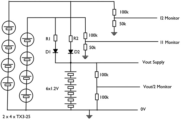
Circuit for the Tumbleweed power supply. This circuit charges a battery when it can, and provides for monitoring the battery voltage and charging currents. You can remove the bits of the circuit you don’t need or clone the solar array and charging monitor parts if you have more arrays. If you have more than one array or even only one array and a battery, though, you need a blocking diode for each.
When to Use Solar Cells
The most obvious applications for solar power are outdoor devices with modest power needs of a fraction of a watt. Very low power applications and indoor systems can be driven much more easily with an alkaline battery (although note that a solar cell circuit might be lighter). For powers of a few watts or more, solar power can be rather expensive. On the other hand, solar driven devices can be aesthetically pleasing and, for lawn lights or weather stations or other applications where it is convenient not to have to replace batteries, solar power can be a bright idea. NV
SOURCES
SOLARBOTICS
(www.solarbotics.com) has a range of amorphous Sunceram cells for small robot projects such as solar engines.
EDMUND SCIENTIFIC
(www.scientificsonline.com) has a range of solar cells, multi-cell panels, low-current motors, and various experiment kits.
JAMECO
The Iowa Thin Film cells are available from (www.jameco.com) and are from three to 12 volts with a range of currents and plastic coatings.