“Whether you’re new to the Arduino or an old fan, the ProtoSnap Pro Mini is worth exploring.”
One of the great things about open source hardware — such as the Arduino — is competition and variety. A quick search on the Internet will reveal Arduino-compatible boards that are smaller, faster, cheaper, or more feature-laden than those offered by rivals. It’s the same for add-ons and books – there seems to be no end to inexpensive sensors and other add-ons from China and books from publishers in the US and EU.
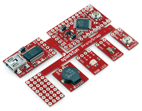
This is a review of the ProtoSnap: an Arduino-compatible board from SparkFun Electronics (www.sparkfun.com). There’s a great tutorial on the $45 board at the SparkFun website, complete with close-ups of the board and source code. As you can see from the photo, the little board — which easily fits on the active screen area of an iPhone — consists of a Pro-Mini 5V/16 MHz microcontroller, a USB interface pad, a button pad, light sensor pad, RGB LED pad, buzzer, and prototyping pad.
Why ProtoSnap?
Of all the Arduino-compatible boards, why consider the ProtoSnap? After all, it’s not the cheapest or fastest board on the market, but it’s perfect for the budget-minded novice. It’s perfect for beginners because there’s no need to hook anything up, other than the USB cable to your PC, Mac, or Linux box. You can experiment with the microprocessor, the buzzer, LED, light sensor, and button without going for a soldering iron or solderless breadboard kit. The USB cable supplies power and enables you to download code to the microprocessor.
In a way, the ProtoSnap is much like a project board with a dedicated processor. These boards typically feature a large solderless breadboard area with microprocessor, sensors, and other devices mounted on the periphery of the board. You can’t do much with these boards without first connecting the pins of the microcontroller to the components with jumper wires.
From a budgetary perspective, traditional project boards are fine for prototyping, but not for deployment. You might extract the microcontroller — assuming it’s not integrated in the board — but you’ll have to purchase a new board and sensors for actual use. With the ProtoSnap, once you’ve figured out your design and programmed the microcontroller, you simply snap the components free and use the pads you need for your project. Of course, the economics of this equation depend on whether your project calls for a buzzer, LED, light sensor, and/or pushbutton.
Board Check
When you first attach a USB cable to the FTDI interface pad, you might be startled to see the RGB LED cycle through red, green, and then blue. According to the documentation in the 50-line source code (also available on the SparkFun website), the LED is intended to cycle when the light sensor is in the dark. I suppose my workbench isn’t illuminated as brightly as it could be. I verified the function of the light sensor by bringing my work lamp closer to the board. The LED stopped cycling.
Depressing the button activates the buzzer which is pleasantly subtle, as buzzers go. Some of the buzzers that ship with evaluation boards are loud enough to cause hearing loss. The demo source code is typical Arduino which means it’s easy to read and modify. I changed the sensitivity of the light sensor so that it triggered on less light. It’s a bit odd that the LED — which is surprisingly bright — is located immediately adjacent to the light sensor.
If you work the button with the LED active, you’ll recognize one aspect of the Arduino code: the sensor handling is sequential. If the processor is handling the button down and buzzer, it can’t cycle the LED. As a project, see if you can make the buzzer sound whenever the button is pressed.
Note that the board setting for the ProtoSnap is “Arduino Uno.” If you set the set the board to “Mini Pro”, (as I did), you’ll find the microcontroller unresponsive.
Next Steps
Once you’ve worked through the sample source code, you should be ready for your first real project. Take a look at the sample code available within the Arduino development environment, under ‘Examples’. Most of these examples don’t require sensors or pushbuttons. A good first step would be to integrate the sensors and buzzer with the example code. Of course, there’s nothing like working on your pet project.
As a ‘rhythm-challenged’ student of the electric guitar, one of my long-time plans has been to construct a foot pedal that sequences light to silently indicate how closely I’m keeping time with my foot. That is, say, white on beat one, red on two, green on three, and blue on four. I’d associate a handful of high power LEDs with each beat.
The little ProtoSnap kit was just the thing to get me working on this project. The pushbutton is a perfect prototype for a foot button, and the RGB LED was just the thing to prototype the planned array of red, green, and blue LEDs.
/*<br />
RGB LED Sequencer for ProtoSnap Pro Mini<br />
Bryan Bergeron<br />
*/<br />
<br />
int button = 7;<br />
int beatcount = 0;<br />
int red = 3;<br />
int blue = 6;<br />
int green = 5;
void setup()<br />
{   <br />
Serial.begin(9600);<br />
pinMode(red, OUTPUT); <br />
pinMode(green, OUTPUT); <br />
pinMode(blue, OUTPUT);<br />
pinMode(button, INPUT);<br />
}
void loop()<br />
{ <br />
if(digitalRead(button) == LOW)<br />
{<br />
beatcount = beatcount + 1;<br />
if (beatcount > 3)<br />
{<br />
  beatcount = 0;<br />
}<br />
delay(250);<br />
}
switch (beatcount){<br />
case 0:<br />
  digitalWrite(red, LOW);<br />
  digitalWrite(green, LOW);<br />
  digitalWrite(blue, LOW);<br />
  break;
case 1:<br />
  digitalWrite(red, LOW);<br />
  digitalWrite(green, HIGH);<br />
  digitalWrite(blue, HIGH);<br />
  break;
case 2:<br />
  digitalWrite(red, HIGH);<br />
  digitalWrite(green, LOW);<br />
  digitalWrite(blue, HIGH);<br />
  break;
case 3:<br />
  digitalWrite(red, HIGH);<br />
  digitalWrite(green, HIGH);<br />
  digitalWrite(blue, LOW);<br />
  break;<br />
}
}
The code (shown above) is simple enough. Start by initializing variables. Then, set up the input (button) and output (LED) pins. The main loop consists of reading the button which is LOW when depressed. A button press increments the beatcount variable by one, and the switch statement illuminates the R, G, or B, or all three components, depending on the value of beatcount.
The most interesting line of the code is:
Delay(250);
This line provides signal conditioning for the pushbutton, in the form of a 250 ms delay following the first button press. Because the switch contacts bounce when they first make contact, the button doesn’t go from open to closed, but opens and closes several times after the initial press. Without the delay, the beatcount variable could be incremented dozens of time by a single button press. There are, of course, more sophisticated button signal conditioning routines, but this one works well for a simple on-off button.
Another way to handle the contact bounce problem is to insert a low pass filter — in the form of a resistor and capacitor — in line with the switch. The simple RC filter — while saving a line of code — is relatively expensive if you consider the components, PC board real estate, and the time to insert and test the components. Furthermore, if you change the switch to another brand or model, the RC filter components may need to be changed to handle the bounce characteristics of the new switch. Changes in software, on the other hand, are trivial.
That’s it. My prototype is just about done. My next step is to use the prototyping area to install three small solid-state relays. I’ll energize the relays instead of the RGB LED, and have a way to control the much more powerful and power-hungry banks of LEDs that I’m building for the project. I could snap off the microcontroller, add a battery supply, and wire in a foot pedal switch, but I think I’ll leave the assembly intact for my next prototype. It’s handy having a three-mode LED and switch to work with, without having to dig for wires or my soldering iron.
Room for Improvement
Nothing’s perfect, and every electronics product is designed to provide a list of features at some price point. In this case, the only real area in need of improvement is the USB interface pad. The interface works fine, but once you unsnap the pad from the microcontroller, you’ll have to take out your soldering iron to reconnect the two if you want to reprogram the microcontroller. It’s a simple enough task to install headers on the microcontroller and USB pad, but you’ll need to think ahead and order the parts when you buy the ProtoSnap. Also, you’ll need to supply a mini USB cable.
Bottom Line
Overall, this is a great product for beginners — especially beginners without an inventory of parts. I can easily see this used in the classroom, where the teacher doesn’t have to contend with keeping track of components, wires, and other parts. The ProtoSnap offers a lot in an affordable compact package, and the design makes it painless to move from prototype to product. NV