Some Hot Topics for a Cool Hobby
While not strictly a ham radio topic, hams certainly have to deal with managing a surplus of heat. From an extra-hot 1/4 watt to getting hundreds of watts away from the business end of a linear amplifier running a “full gallon,” hot spots need attention! Let’s see about giving a few important ideas the third-degree, including an easy experiment you can do on the bench.
Ohm’s Law for Heat
Everywhere current flows, heat is dissipated, and the amount of heat is measured in watts; the same as electrical power. For a resistor, the amount that must be dissipated is Pd = I2R. In general, wherever a voltage drop and current flow exist at the same time, Pd = V x I. Heat is released into the surrounding environment through the component’s body or via its leads into the supporting circuit board or even other components.
If there is too much heat, the component can change its characteristics or suffer damage. It’s up to the circuit designer to “take the heat” and be sure that doesn’t happen. To do that, you have to understand a fundamental relationship of heat transfer.
Don’t panic — no thermodynamics involved! If you’re comfortable with Ohm’s Law, you’ll recognize this new equation right away. Instead of R for resistance, here’s a new term: thermal resistance, θab. Thermal resistance is the resistance to heat flow between two points: a and b.
Metals have a very low thermal resistance, and insulating materials like glass or air have fairly high thermal resistance. Although it’s not a hard and fast rule, the thermal resistance for electrical conductors is low, and for electrical insulators, it’s high. The analogy with electricity even extends to this equation:
P x θab = Ta - Tb = Tab = ΔT
Temperature difference, ΔT, between the two points (a and b) is equal to the power, P, flowing between the points times the thermal resistance along that path, θab. If you think this looks a lot like the V = I x R form of Ohm’s Law, you’re right. T can be thought of as a “heat voltage,” P as a sort of “heat current,” and θab as “heat resistance.” T is usually specified in °C, P in watts, and θab in °C/W. (You can see why the ancients thought heat must be some kind of fluid!)
The more power that flows through a given thermal resistance, the higher the temperature difference will be. If several different thermal resistances are encountered by the flowing heat, then the total thermal resistance is θab = θ1 + θ2 + ... + θn — just like resistors in series. Temperatures at each step are calculated just like voltages in a voltage divider.
Armed with this equation, we can now take four steps to manage heat. Figure 1 illustrates how this works — just like Ohm’s Law.
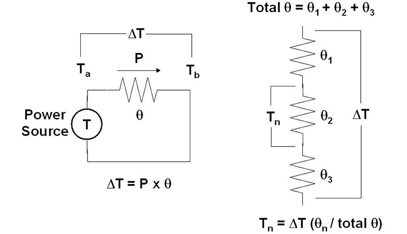
FIGURE 1. The basics of understanding how heat flow turns into a temperature difference are very similar to Ohm’s Law for voltage, current, and resistance.
Picking a Heatsink
Websites and online catalogs have hundreds of variations of heatsinks — how do you pick one? Like most problems that look complicated, you can whittle them down step-by-step until the choice has been narrowed to just a few. The following four steps are how most design engineers approach the problem (assuming they don’t have fancy software to do it!).
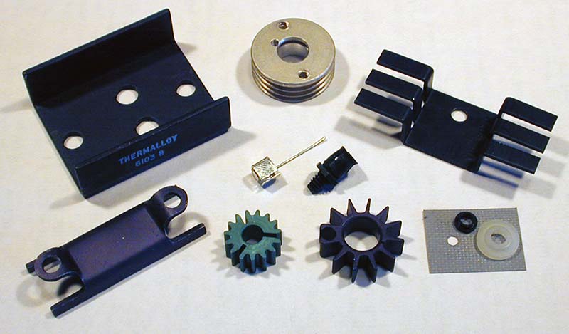
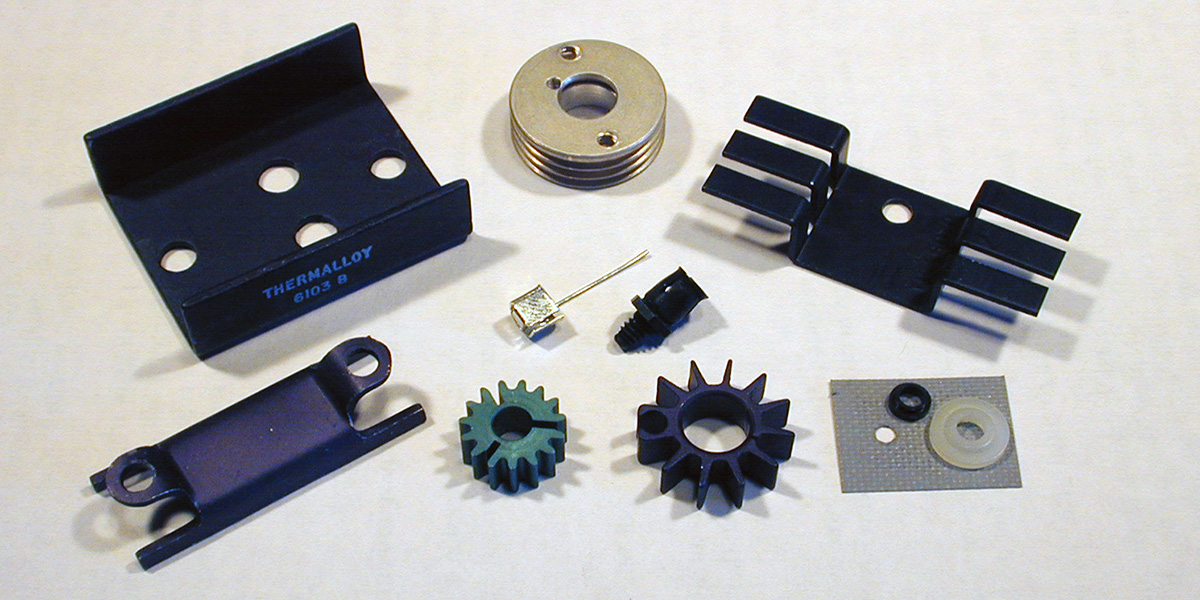
FIGURE 2. Several common heatsinks for power transistors, voltage regulators, and small amplifier modules. These have thermal resistances from 15 to 55 °C/W. Some clip directly onto a transistor case (the ones in the middle), while others are held on with screws, such as the mounting hardware shown at lower right.
Step 1 — Determine How Much Heat is Generated
Here is a list of the heat-generating equations for common components:
Resistor: Pd = I2 x R = V2 / R = V x I
Diode, SCR, or TRIAC: Pd = Vf x Iavg where Vf is the component’s forward voltage drop across its internal junction(s), and Iavg is the average forward current through the junction. This is why power rectifiers get so hot; for every amp of average current through them, they are dissipating at least 0.7 watts.
Transistors: Pd = VCE x IC = VGS x ID. The transistors act like variable resistors as far as heat generation goes. This is a particular concern where the transistor is used to regulate current, such as in a voltage regulator’s pass transistor. This forms the basis of our experiment coming up later.
Inductor, Capacitor, Transformer: Pd = I2 x RLOSS. Capacitors have loss? You bet! It’s called the equivalent series resistance (or ESR) and its created by loss in the dielectric or electrolyte and from resistive losses in the metal electrodes. ESR is quite important when choosing a capacitor for use in a switchmode supply or converter where the AC currents can be quite high.
In these equations, if the current is AC, use RMS values. For either DC or AC currents that are intermittent, multiply Pd by the duty factor of the current. For example, if a resistor only carries current in pulses that are on three-quarters of the time, calculate peak Pd and multiply by .75.
When you are using an IC, sum up all of the power dissipation from each significant source of heat. These are usually the IC’s outputs. Include the power dissipated inside the IC by multiplying the power supply voltage times the current drawn by the IC.
2 — Determine Maximum Power or Temperature
“Bulk” components — such as resistors and capacitors — generate heat throughout or along their bodies. A maximum continuous power dissipation, Pdmax, is specified, such as for a half watt resistor. An ambient temperature is also specified for Pdmax, because that determines the temperature at one end of the component’s thermal resistance.
Semiconductors, on the other hand, generate heat in the very small volume around the junctions or channels that conduct current. This small source of heat is generally referred to as “the junction,” whether it’s an actual P-N junction or an FET channel or something else. For semiconductors, thermal resistance is specified between the heat-generating junction and the surrounding or ambient conditions, as θja. This is referred to as the junction-to-ambient thermal resistance.
If the semiconductor is intended to be used with a heatsink, θjc is specified as the thermal resistance from the junction to the case of the transistor, which might be a metal tab or just the external plastic surface. The total thermal resistance, junction-to-ambient, θja, then becomes the sum of θjc and whatever thermal resistance exists from the case to ambient conditions, θca.
The internal structure of semiconductors must be kept below some maximum temperature, Tjmax, or it will be destroyed. For devices made from silicon, this is usually 150°C. For a given amount of power dissipation, the junction temperature, Tj, will be:
Tj = Tambient + P x θja
If you calculate Tj and find it to be less than Tjmax, you can stop there.
You have to be careful when assuming an ambient temperature. In an enclosure, the actual ambient temperature may be quite a bit higher than room temperature. You also need to include a safety factor when deciding on what an acceptable junction temperature will be; 25 percent or 35°C is reasonable.
If you find Tj to be on the high side, you must reduce either P or θja. Reducing P depends on the application of the component. Reducing θja means helping the component pass heat more effectively through its outer surface since θjc, the thermal resistance from the junction to the outer surface, is fixed.
3 — Selecting a Method to Get Rid of the Heat
There are two common methods of removing excess heat from a component. The first is to cool it by moving enough air across the component to keep Tambient as low as possible, i.e., blow on it. This will work for relatively low power dissipations of up to a watt or so with small components.
To remove higher amounts of heat, a heatsink is required to lower θca. A heatsink can be anything sufficiently massive and thermally conductive to conduct heat away from the component so that it can be dissipated. For example, the metal enclosure of many handheld radios acts as the heatsink for the output amplifier, getting rather warm during prolonged transmissions.
A Pipeful of Heat
Inside a PC, the many watts of heat dissipated by the main processor (and some graphics processors in high-performance PCs) are conducted away from the processor by a heat pipe. One end of a tube is mounted directly to the package of the processor, and the other is mounted on a heatsink or formed into a heatsink.
The working fluid in the pipe flows from the hot end (on the processor) to the cold(er) end at the heatsink, then back again to the processor. This is a simple form of a heat engine that drives a mechanical motion (fluid flow) by using a temperature difference.
The larger the temperature difference, the faster the fluid flows — just like voltage driving a motor.
4 — Select an Appropriate Heatsink
Heatsinks are specified by their thermal resistance in °C/W. The rating tells you how much the surface temperature of the attached component will rise per watt of heat flowing through that surface. This figure generally assumes natural convection, assuming that the only air movement is caused by warm air rising.
To select a heatsink, you need to specify the maximum body or junction temperature. Calculate the amount of power the component must dissipate. Estimate the ambient temperature. Remember that qjc is fixed, so you calculate the maximum case temperature. The required thermal resistance is:
θca = (Tcmax - Tambient) / P where Tcmax = Tjmax - P × θjc
Now, you can pick a heatsink design that fits your component and your available space.
Be careful when using a heatsink inside an enclosure or where free air flow is not guaranteed. Thermal resistance can be significantly higher just by preventing hot air from moving away from the heatsink. In these situations, a fan or blower is used (or a heat pipe as mentioned in the sidebar). Manufacturers of heatsinks often have application notes or guidelines on their websites to help you in these situations.
A good technique to get around not having free air flow in an enclosure is to mount the heat dissipating component directly on the enclosure wall. Using the enclosure as the heatsink allows the heat to flow directly to the outside air.
Be aware that the longer leads involved with connections to the power dissipating device may become significant at higher frequencies. At RF, this technique generally requires the entire amplifier module or circuit be mounted on the enclosure, and a coaxial cable connection be made to any internal circuit board.
Why Use Thermal Compound?
If you take a power transistor or IC off its heatsink, there is usually a thin coating of a white or clear grease-like substance between the component case and the heatsink. What is that stuff?
Surprisingly, it’s not particularly thermally conductive! However, it is better than air.
The function of this thermal compound is to fill in any gaps between the case and the heatsink. Air is a bad conductor of heat, as we find out when we buy insulation for our homes which has an R-rating in equivalent inches of air. Any gaps, warps, or pits in the surface of the case or heatsink cause big increases in thermal resistance.
Thermal compound fills in those imperfections and even though it’s not as good a conductor of heat as metal, a thin layer of it is better than just bolting the surfaces together. The key word is “thin.” All you need is a few thousandths of an inch of compound to do the job.
Put a thin coating on either surface, press the surfaces together, twist or slide them a little bit to even out the coating, and then tighten the mounting screw or clip. Yes, it does get all over everything, including your fingers — that’s its job!
The much cleaner thermal pads or washers also work, but not as well as the compound.
A Heat Management Experiment
Nothing instructs like putting a fingertip on a hot component, so let’s get cracking!
Three-terminal voltage regulators used in power supplies often require heatsinking. One of the most common applications is dropping a 12V input voltage to 5V with a 7805 for use with digital logic. (You can find the 7805 datasheet at www.sparkfun.com/datasheets/Components/LM7805.pdf.) This circuit is shown in Figure 3. Construct it by tacking the components together since the current levels will be too high for a solderless breadboard.
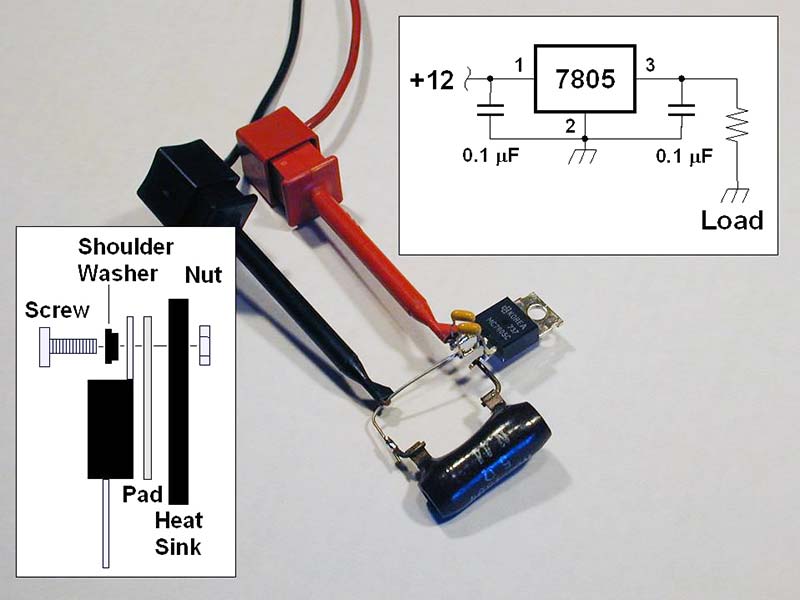
FIGURE 3. The three-terminal voltage regulator circuit for experimenting with power dissipation. Insets show how to attach the regulator’s TO-220 package to a heatsink. The circuit uses a power resistor as the load, and power is supplied by the clip leads.
To test this circuit, you’ll need a beefy load that can draw up to one amp. A 5Ω/5W resistor can either be purchased or constructed from a combination of resistors in series or parallel. It will get warm!
- Start with a light load of 100 ohms and no heatsink. Apply 12V to the regulator input pin. The total power dissipated in the load is V2 / R = 25 / 100 = 1/4W. The regulator dissipation will be equal to the voltage across it (12-5V) times the current through it, Pd = 7 x 0.1 = 0.7W. In this case, the regulator dissipates more power than the load! Let this circuit “run” for a while and test the 7805 case temperature with your fingertip (carefully).
- If you have a thermometer or temperature measuring probe, take a temperature reading of the case. Calculate the junction temperature of the regulator by using the datasheet’s value for θja: Tj = 0.7W x 5°C/W = Tambient + 3.5°C. The case should be just noticeably warmer than the surrounding air.
- Attach the 5Ω load and turn on the power. The case of the regulator will get QUITE hot, so don’t touch it. The regulator has to get rid of 7V x 1A = 7W! What is Tj now (Tambient + 35°C) ? The regulator will quickly enter thermal shutdown where it cuts off the output current at high temperatures. You will see the output voltage drop as the IC shuts down. This is a feature — not a bug — as it keeps the IC from burning itself up and often whatever it’s connected to as well.
- Attach a heatsink as illustrated in the figure. If you don’t have insulating hardware, be sure not to let the heatsink touch any other part of the circuit since it’s connected to the regulator’s case directly. Turn on the power once again and check the temperature one more time. Cooler, isn’t it? If you can measure temperature, calculate Tj.
- Experiment with different input voltages, types of heatsinks, scraps of printed circuit board material or metal, a metal enclosure, whatever’s handy. Measure the temperature with a fan blowing on the heatsink. Put the circuit under a cover to simulate an enclosure with no air flow.
You’ll quickly get a feel for what works as a heatsink and what the effects are. NV
Beyond the Breadboard
Using heatsinks is just one aspect of building your own electronic stuff. As you gain experience, bit by bit, you’ll find yourself tackling more advanced projects.
To help you get on the way to some serious bench time, check out the ARRL’s Tech Portal at www.arrl.org/tech-portal and the Circuit Construction page at www.arrl.org/circuit-construction. There are tons of good tips for electronic aficionados just getting started and moving beyond the breadboard stage of building.