After decades of seeing projects and circuits using ever increasingly complex integrated circuits, I yearn for simpler times. As a teenager, I built fascinating and wondrous circuits using just a few transistors. My flashlight controlled relay could control a buzzer; music from my cassette tape player played on my radio with a two transistor circuit; my amplifier could drive a speaker. These circuits were from dusty hobby books found at my local library with names like “29 transistor circuits” or “electronic hobby circuits.”
Transistor Clock
To return to those glory days, I decided to build a digital clock using only transistors as the active elements. After a few years of “work” (it felt more like play), the final parts count is 194 transistors, 566 diodes, 400 resistors, and 87 capacitors. Check it out in Figure 1.
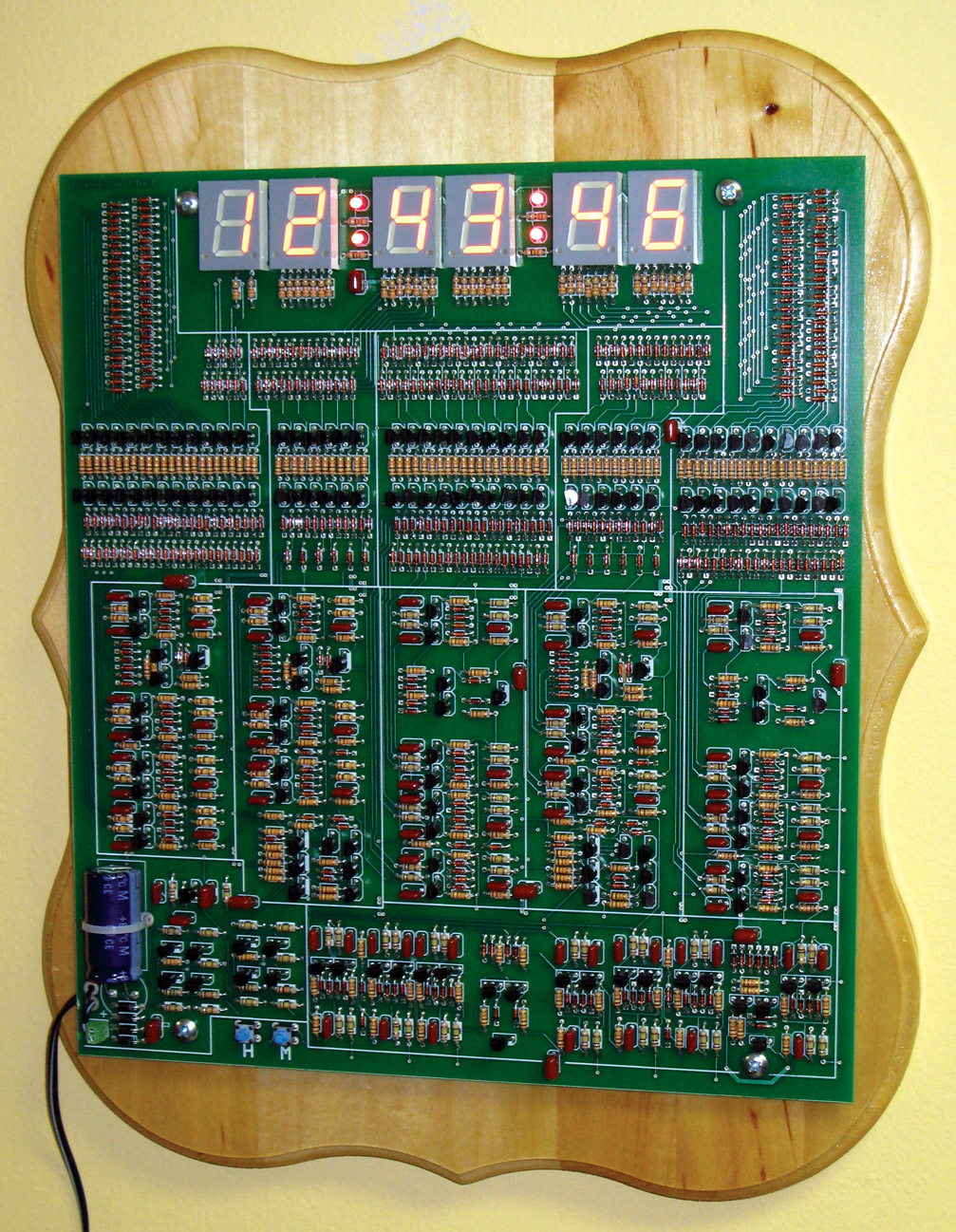
FIGURE 1. Transistor Clock.
This article will explain the circuitry at both the logic level and the transistor level. Time to get started ...
The Big Picture
Figure 2 shows the design at the functional block level. The power supply (lower left) rectifies and filters the incoming nine volts AC, converting it to nine volts DC to operate the circuitry and a 60 Hz clock. Next, a prescaler divides the 60 Hz by 10 and six, resulting in a 1 Hz clock. A 2 Hz clock is also routed to the time setting switches.
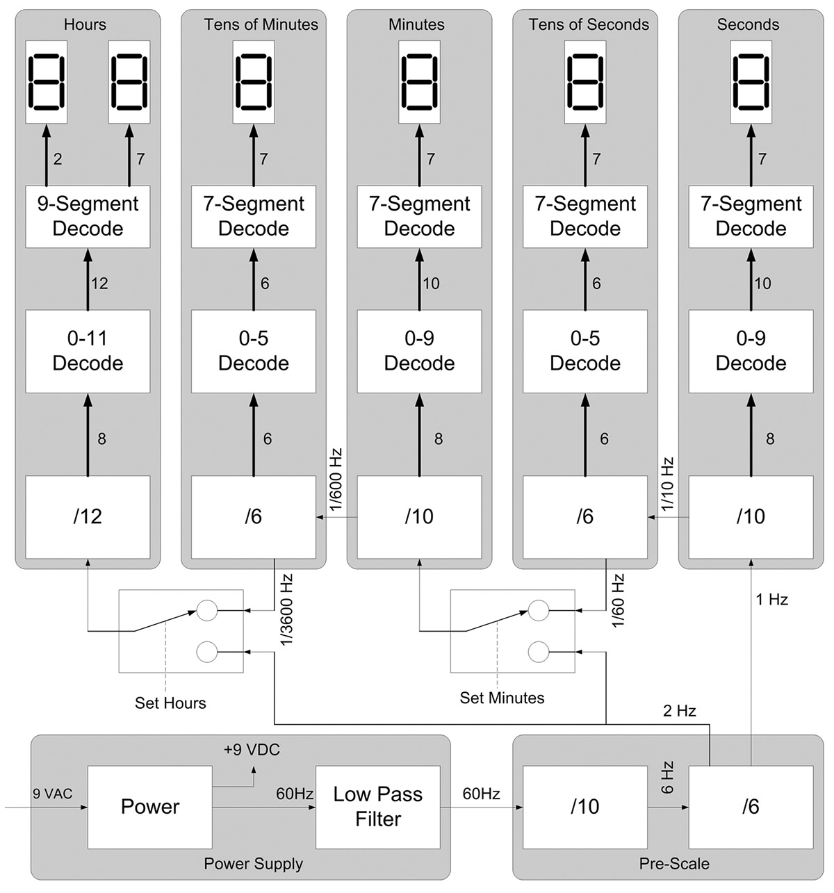
FIGURE 2. Top Level Block Diagram.
The 1 Hz — which is also a one second per pulse clock — drives a divide-by-10 counter who’s output is 10 seconds per pulse. The four bits of the counter are decoded into a one-of-10 signal that drives a seven-segment display showing seconds. The high bit of this counter drives the next counter in the chain: a divide-by-six counter showing tens-of-seconds. Following that is another pair of counters: ÷6 and ÷10, showing minutes and tens-of-minutes. A divide-by-12 counter completes the clock by showing hours.
Flip-Flops
The heart of this clock is the two transistor toggle flip-flop shown in Figure 3. The bi-stable circuit in Figure 4 will be used to explain the operation of the toggle flip-flop.

FIGURE 3. Toggle Flip-Flop.
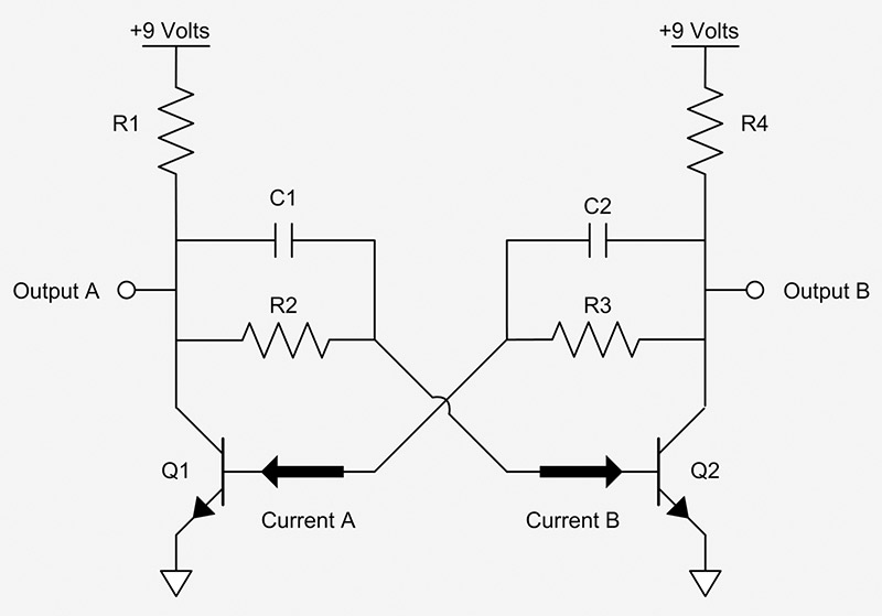
FIGURE 4. Bi-stable Circuit.
Assume that transistor Q1 is in the off state. The collector of Q1 is high impedance so Output A is pulled high by R1. A current flows through R2 (current B) into the base of Q2 switching Q2 “on” so Q2 conducts and pulls output B to ground. No current flows through R3 (current A) so Q1 is off (which is the initial assumed state). This is one of two stable conditions. The other stable condition is Q1 on and Q2 off. Note that they both cannot be on and they both cannot be off.
It’s Toggle Time!
Assume the previous condition with Q1 off and Q2 on. Output A is high; current B is flowing into the base of Q2 so Q2 is on and output B is low. Imagine that current B is somehow interrupted for a moment. Q2 will turn off, output B will start to be pulled high by R4, and current A will start to flow through R3 and C2. Q1 will tune on, pulling output A low. The flip-flop has “flipped” to the other state. In other words, it has “toggled.”
Consider Figure 3 again. The two diodes connecting bases to the input allow a short negative-going pulse to “steal” the base current for a moment on the falling edge of the input, causing the flip-flop to toggle.
Counters
The clock is made of a collection of counters. Counters made by a chain of n flip-flops result in binary ripple counters capable of dividing by 2n. A four flip-flop counter naturally counts from 0 to 15. To make it count from 0 to 9, it needs some steering logic on the flip-flop toggle inputs. Figure 5 shows four flip-flops, the logic, and the internal clocks driving each flip-flop to make a divide-by-10 counter.
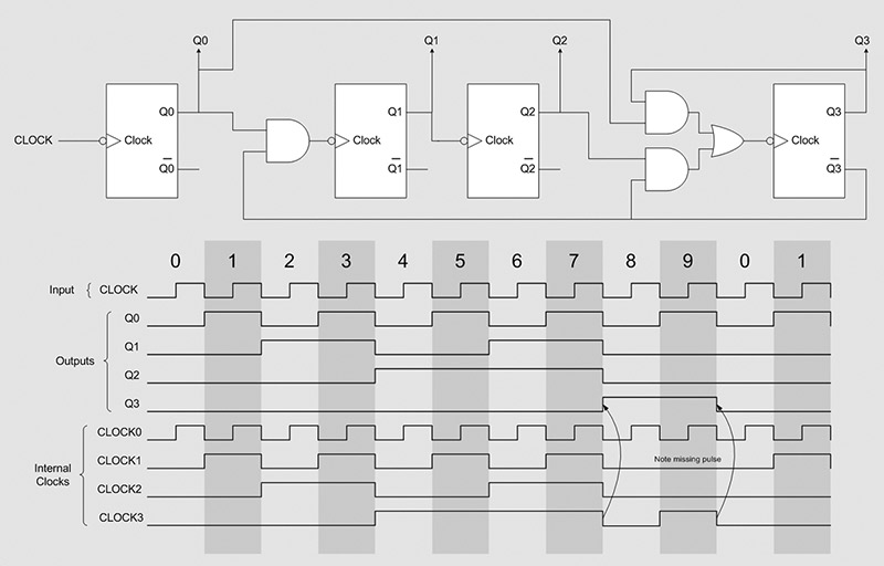
FIGURE 5. Divide-by-10 Logic.
Note that at count 9, the clock to the second flip-flop is masked by the logic causing state 9 to transition to state 0, rather than state 10. One weakness of this approach is that if the counter powers up into a state higher than 9, it takes a few counts to get back on track.
Figure 6 is a divide-by-10 counter transistor schematic of the logic circuit; note the two diode OR gate and the three transistor AND-OR gate.
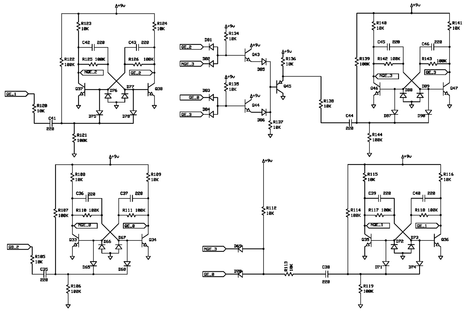
FIGURE 6. Divide-by-10 Implemented with Transistors.
Decoders
The output of the counters is decoded into one-of-n, meaning the divide-by-six counter drives one of six lines; the decade counter drives one of 10 lines; and the hours counter drives one of 12 lines. For each numeric display, the decoded lines drive a diode array that implements a wired OR function. Figures 7 and 8 show the seven-segment decoder in action.
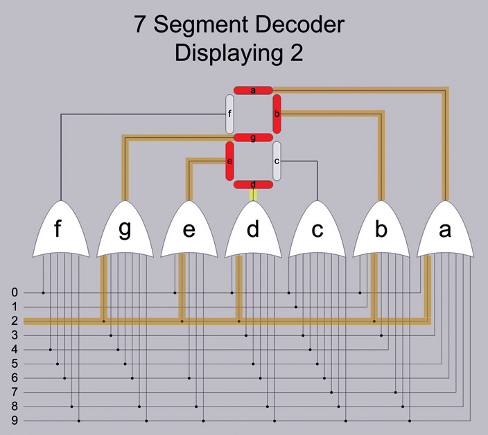
FIGURE 7. Seven-Segment Decoder.
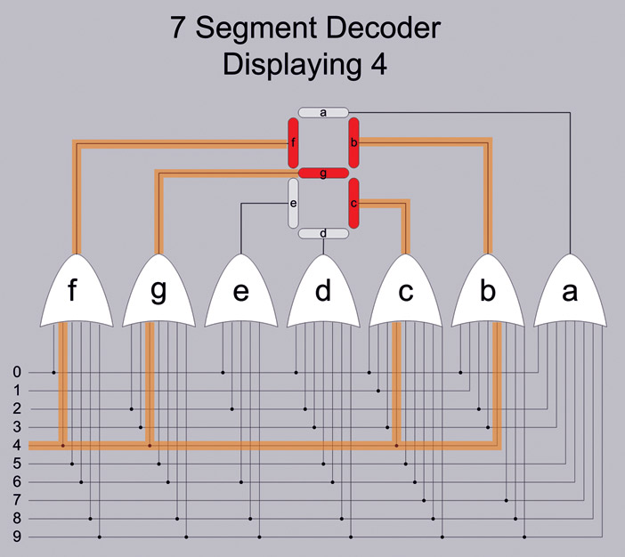
FIGURE 8. Seven-Segment Decoder.
60 Hz Extraction
This clock uses the 60 Hz signal from the power company as a time base. Unfortunately, the power signal has spikes on it from equipment switching on and off, and these spikes can trigger the counters and falsely advance the time if allowed to propagate to the counters. Previous attempts to place an analog RC low pass filter on the 60 Hz did not prevent all power spikes from erroneously advancing the time. I devised a “brick wall” low pass filter with a cutoff at about 100 Hz. The logic is shown in Figure 9 and the transistor implantation is in Figure 10.
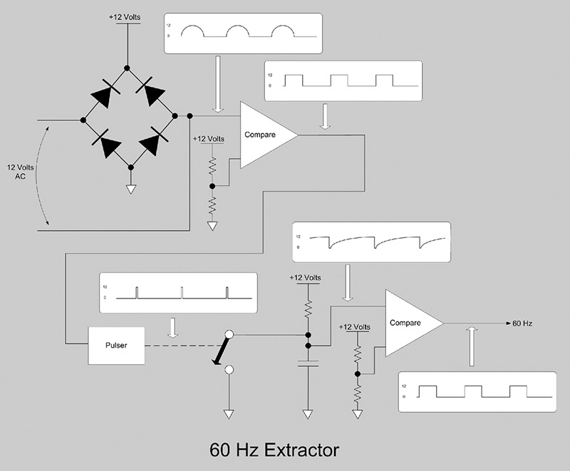
FIGURE 9. 60 Hz Extraction Logic.
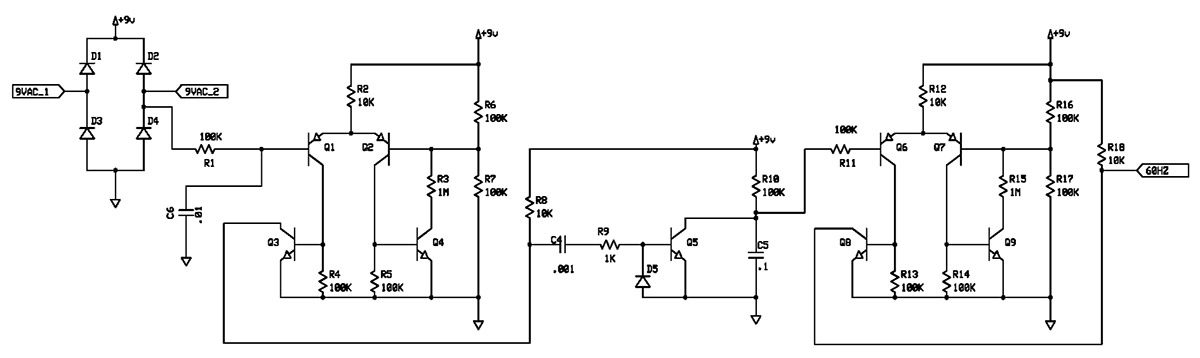
FIGURE 10. 60 Hz Extraction Circuit
In short, the 60 Hz sine wave is squared up, a pulse is developed from one edge, the pulse discharges a capacitor which charges up at a calculated rate, and the capacitor voltage is level compared to produce 60 Hz. The point of all this complicated rigmarole is that when a noise spike causes an extra pulse, it merely discharges the capacitor and causes a delayed edge on the output of 60 Hz so that the noise affects the duty cycle, not the frequency. It would be possible that a long noise burst could remove one cycle, but that rare likelihood has the almost unnoticeable effect of losing 1/60th of a second. The transistor implantation in Figure 10 shows two four-transistor comparators with hysteresis and the pulsardischarger circuit.
Building the Clock
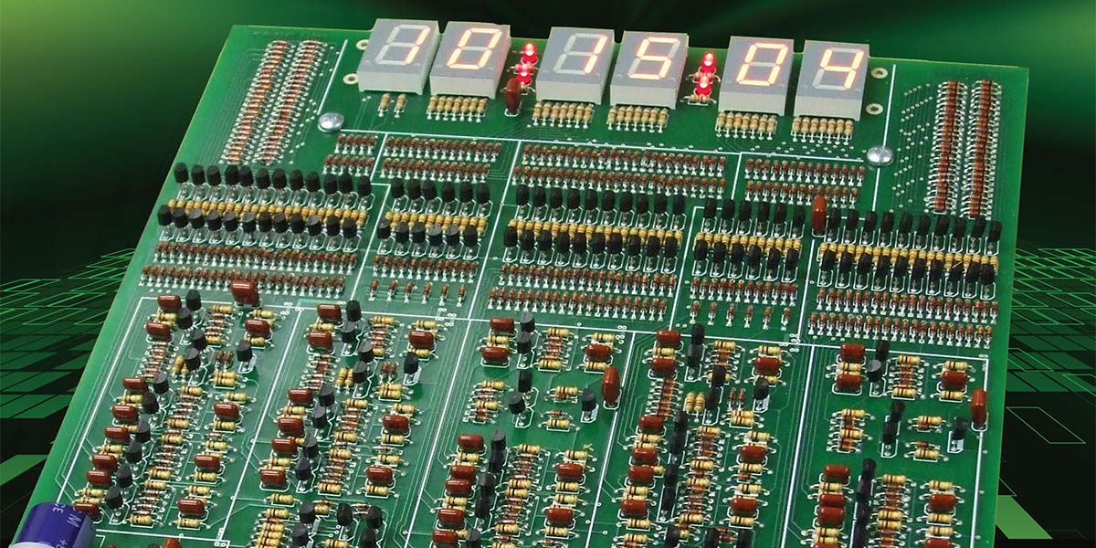
While you could build this clock on perf-board by wiring individual components, with over 2,700 connections you would need to be committed — or at least you should be. Building the clock using the available PCB (printed circuit board) is recommended. A full kit, including the board is available in the Nuts & Volts webstore. An interesting aspect of the PCB is that a parts placement guide is not needed — everything is printed on the PCB. Check out the parts values shown in Figures 11 and 12. Building instructions and debugging hints are in the online manual located in the downloads file below.
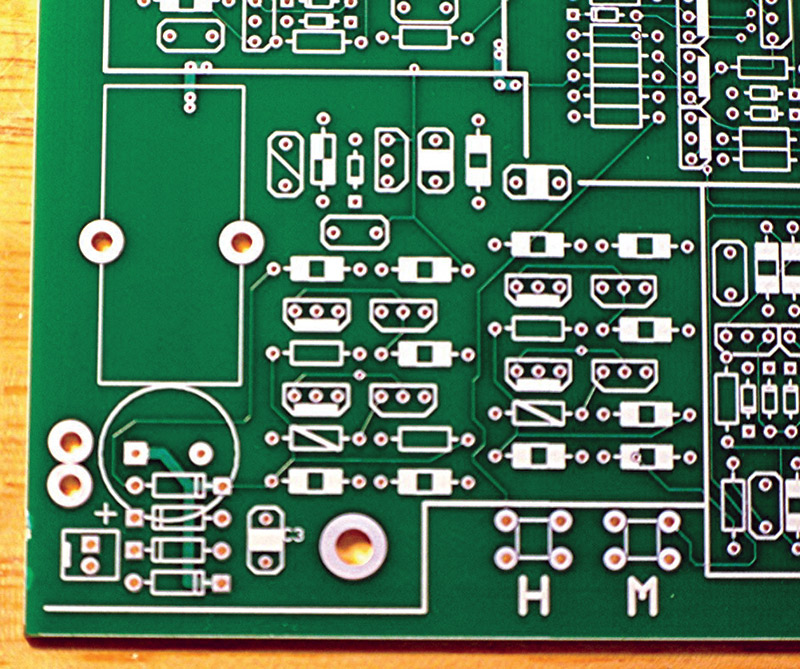
FIGURE 11. Portion of PCB Showing Silkscreen.
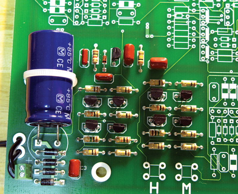
FIGURE 12. Loaded Section.
Conclusion
Hopefully, you have learned a thing or two about top-down design, moving from block diagram to transistors and also a bit about counters and flip-flops. If you want to add a course in soldering, consider building the clock. The resulting wall-mountable clock art will be a great memento of your time and efforts. NV
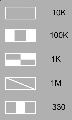
Resistor Codes.
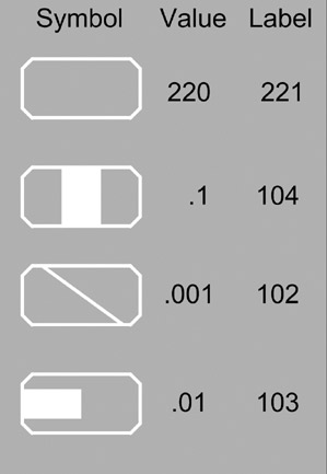
Capacitor Codes.
PARTS LIST
| Part |
Quantity |
Description |
| 220 pF |
75 |
50 Volt PolyCap |
| 0.1 µF |
15 |
50 Volt PolyCap |
| 0.01 µF |
1 |
50 Volt PolyCap |
| 0.01 µF |
2 |
50 Volt PolyCap |
| 6800 µF |
1 |
25 Volt Electrolytic |
| 330 |
41 |
1/4 Watt Resistor |
| 1K |
1 |
1/4 Watt Resistor |
| 10K |
224 |
1/4 Watt Resistor |
| 100K |
111 |
1/4 Watt Resistor |
| 1M |
2 |
1/4 Watt Resistor |
| 2N3904 |
165 |
NPN Transistor |
| 2N3906 |
17 |
PNP Transistor |
| 1N4148 |
556 |
Signal Diode |
| 1N4002 |
4 |
Power Diode |
| 7-seg |
6 |
Common Anode 0.8 inch LSD8161-11 |
| Single LED |
4 |
3 MM Red LED |
| TermBlock |
1 |
2 terminal, 0.1 inch spacing |
| Switch |
2 |
6 mm pc mount |
| Wall xfmr |
1 |
9 volts AC transformer |
Downloads
Transistor Clock Schematics
Assembly Manual with Troubleshooting Guide
FAQs