RECYCLED ELECTRONICS — Giving New Life to Old Tech!
I recycled a VCR knob assembly and turned it into a controller for the Windows Media Player.
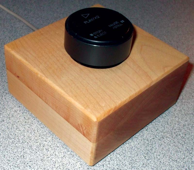
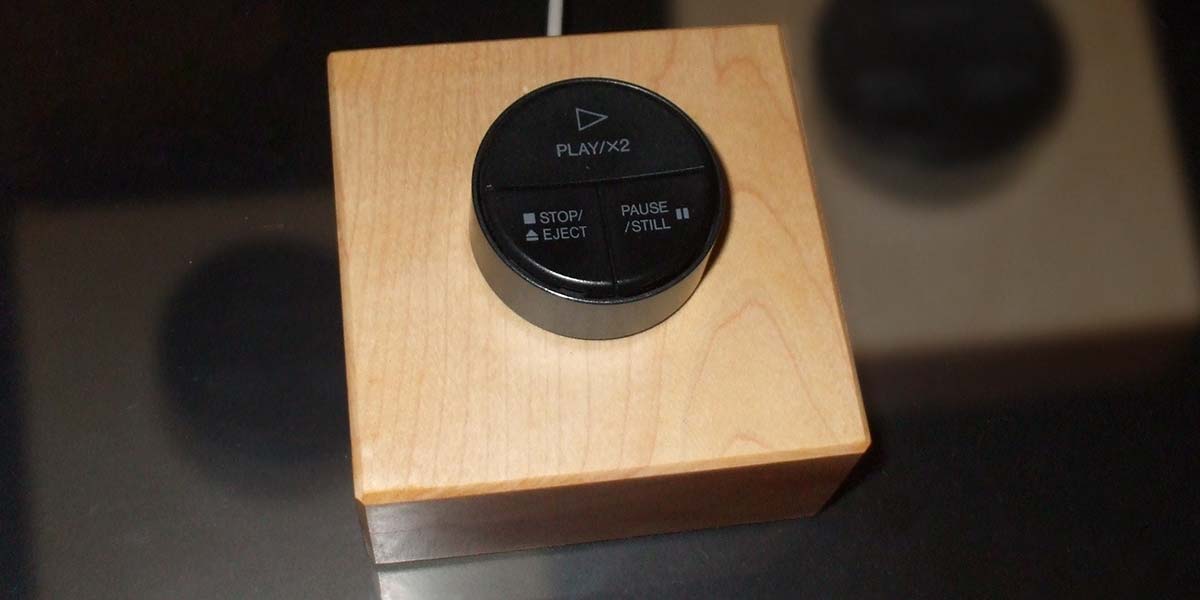
FIGURE 1. A close-up of the VCR knob and the wooden housing.
The knob assembly began its life as the control for a Sharp VCR. The VCR was given to me after it had stopped working. I let my son dismantle the unit because he enjoys opening things up and taking them apart. When the unit was disassembled, I took particular notice of the knob assembly — what it was comprised of, how it was assembled; I was impressed by how much control was put into such a small unit.
In the center of the device were three buttons for play/X2, stop/eject, and pause/still. Around the perimeter was a spring return dial which when rotated clockwise would fast forward and reverse when rotated counterclockwise. It was refined to the point that a lot of thought must have had to been put into its design, and I knew that sooner or later it would end up in one of my projects.
The knob sat in the spare parts pile for awhile before the idea came to me to use it as a media player controller for my computer. While some keyboards have the media player controls built into them, my trusty old IBM model doesn’t. (I still use this relic because I like the feel of the beefy keys when I’m banging away at them.) I had been meaning to do a USB based device and thought the combination of the knob assembly and a PIC16C745 programmed as a media player controller would make for a challenging and useful project. For those of you who may not be aware, the 16C745 is a one time programmable device with low speed USB built into it. If I were to build the controller today, I would make use of one of the full speed, Flash-based USB PIC controllers.
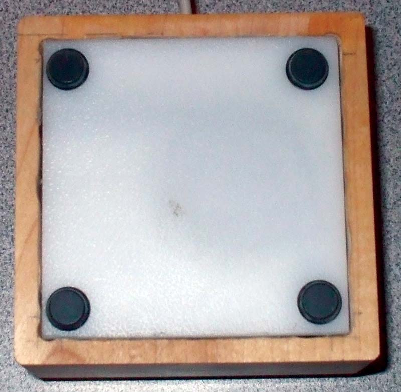
FIGURE 2. The assembled underside of the unit.
Functionality
The play/X2 button became the play/pause button while the stop/eject button became the previous track button; the pause/still button became the next track button. The forward/reverse dial became volume up and down, respectively. I did not try to relabel the buttons because the controls are so straightforward.
The hardware is simple and straightforward too (see the schematic) — a group of switches wired to a PIC programmed to send the required command codes to control the Windows Media Player through a USB port. The hardest part of the project was getting the device to enumerate properly.
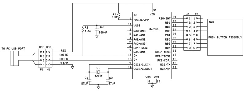
SCHEMATIC.
I made use of a microEngineering Labs (www.melabs.com) PICPROTO 3 board on which to assemble the project. The USB cable is available from Solarbotics (www.solarbotics.com); (SKU 14120) and features a series A USB plug at one end and a locking connector at the other. When the knob assembly was removed from the VCR, it had a unique connector attached to it. I removed the connector and soldered a short section of ribbon cable and an eight-pin connector to it to mate with the eight-pin header on the PICPROTO3 board. With the electronics complete, it was time to select a housing to put it in.
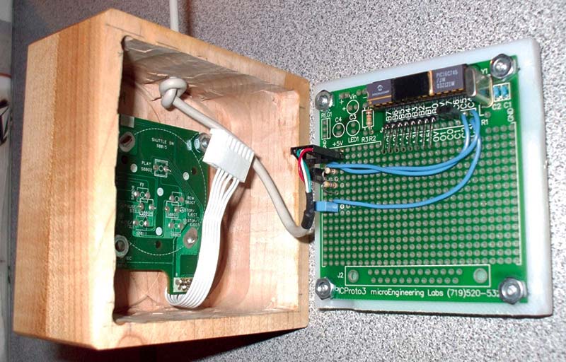
FIGURE 3. The unit opened up, showing the shuttle switch and USB cable on the left half, and the protoboard with microcontroller on the right half.
There were a lot of options to house the controller. I decided to put it into a wooden enclosure which I made from a solid block of sugar maple. This allowed me to make the enclosure as small as possible, making it just large enough to house the PICPROTO board and the knob assembly.
The block was drilled with forstner bits to hollow it out and to make the hole for the shaft of the knob assembly. (Drill the hole for the shaft from the outside first to prevent tear out).
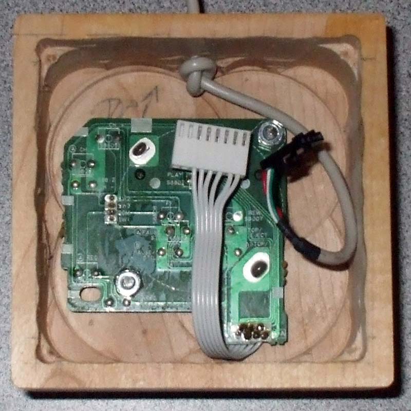
FIGURE 4. The VCR shuttle switch and USB cable in the maple housing. Note the drill marks from the forstner bits.
Next, I epoxied two screws to the inside of the hollowed block and fastened the knob assembly using nuts and lock washers.
After a bit of sanding, the block was finished with tung oil. The pins were removed from the locking receptacle and the USB cable was fed through a small hole in the housing. A knot was tied as a strain relief and the pins were put back into the receptacle housing. The board was mounted to a piece of polyethylene using threaded standoffs. The polyethylene was then “friction” fit into the wooden housing. A couple of rubber feet on the bottom and the unit was ready to rock ‘n roll. NV
Bill of Materials
| ID |
Description |
Qty |
| U1 |
Microchip PIC 16C745 |
1 |
| X1 |
6MHz Crystal |
1 |
| C1, C2 |
27 pF Capacitor |
2 |
| C3 |
200nF Capacitor |
1 |
| R1 |
10K, 1/4W, 5% Resistor |
1 |
| R2 |
1.5K, 1/4W, 5% Resistor |
1 |
| P1 |
USB Cable — Custom |
1 |
| H1 |
Male Header — 4 Pos |
1 |
| P2 |
Female Plug — 8 Pos |
1 |
| H2 |
Male Header — 8 Pos |
1 |
| SW1 |
Play/Pause Knob Assm |
1 |
| — |
Melabs PICProto 3 Bd |
1 |