The 555 timer is a popular bipolar IC that is specifically designed to generate accurate and stable C-R — defined timing periods, for use in various monostable ‘one-shot’ pulse generators, and astable squarewave generator applications. The 555 is also very versatile, and can be used in a variety of special or unusual applications. Some of these include Schmitt triggers, Morse code practice oscillators, electronic door buzzers, continuity testers, signal injectors, metronomes, LED flashers and alarms, and long-period timers.
SCHMITT TRIGGERS
The 555 can be used as a Schmitt trigger by shorting pins 2 (trigger) and 6 (threshold) together and applying the input signals directly to these points, as shown in the functional diagram and circuit in Figure 1.

FIGURE 1. Functional block diagram (within the double lines) of the 555 timer IC, with external connections for use as a simple but useful Schmitt trigger.
The IC’s action is such that (as illustrated by the Figure 1 input and output waveforms) when the input voltage rises above 2/3 Vcc, the IC output switches low, and remains there until the input falls below 1/3 Vcc, at which point, the output switches high and remains there until the input rises above 2/3 Vcc again. The difference between these two trigger levels is called the hysteresis value, and equals 1/3 Vcc in this case; this large hysteresis value makes the circuit useful in noise/ripple-rejecting signal conditioning applications.
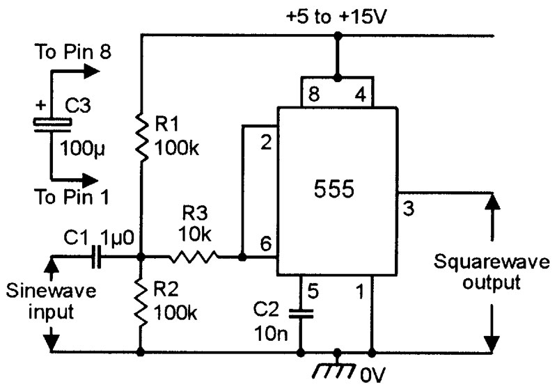
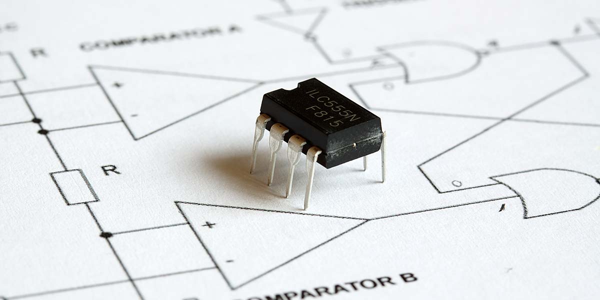
FIGURE 2. 555 Schmitt sine/square converter, with optional RFI suppression via C3.
Figure 2 shows the basic Schmitt circuit modified for use as a high-performance sine/square converter that can be used at input frequencies up to about 150kHz. Potential divider R1-R2 biases pins 2 and 6 to a quiescent value of 1/2 Vcc (i.e., mid-way between the upper and lower trigger values), and the sinewave input is superimposed on this point via C1; squarewave outputs are taken from pin 3. R3 isolates the input signal from the effects of the 555’s switching actions. The diagram shows how optional RFI suppression can be obtained via C3.
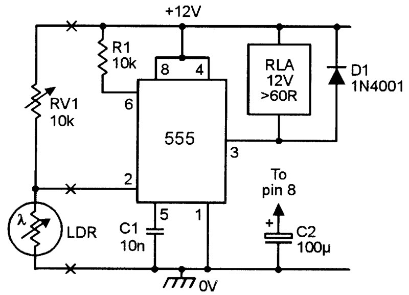
FIGURE 3. Minimum-backlash dark-activated relay switch.
Figure 3 shows the 555 used as a minimum-backlash (zero hysteresis) dark-activated relay switch, with light-dependent potential divider RV1-LDR wired to its input terminal. The RV1 and LDR values are roughly equal at the median switching light level. This circuit acts as a fast comparator rather than as a true Schmitt trigger, since pin 6 is tied high via R1, and the light-sensing RV1-LDR potential divider is applied to pin 2 only. Note that this circuit needs good supply decoupling, which is provided via C2.
FIGURE 4. Alternative input circuits for Figure 3, to give activation by (a) light, (b) under-temperature, and (c) over-temperature.
The above circuit can be made to act as a light (rather than dark) activated switch by transposing the RV1 and LDR positions, as shown in Figure 4(a), or can be made to act as a temperature-activated switch by using an NTC thermistor in place of the LDR, as shown in Figures 4(b) and 4(c); in all cases, the LDR or thermistor must present a resistance in the range 470R to 10K at the required turn-on level.
ASTABLE GADGETS
The 555 astable multivibrator is very versatile and can be used in many applications of interest to both the amateur and professional user. Figures 5 to 11 show examples of typical 555 astable gadgets.
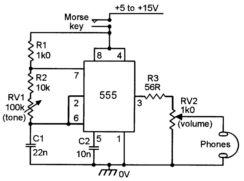
FIGURE 5. Code-practice oscillator with variable tone and volume.
Figure 5 shows a Morse-code practice oscillator, with frequency variable from 300Hz to 3kHz via TONE control RV1. The ‘phone volume is variable via RV2, and the ‘phones can have any impedance from a few ohms upwards. The circuit draws zero quiescent current when the Morse key is open.
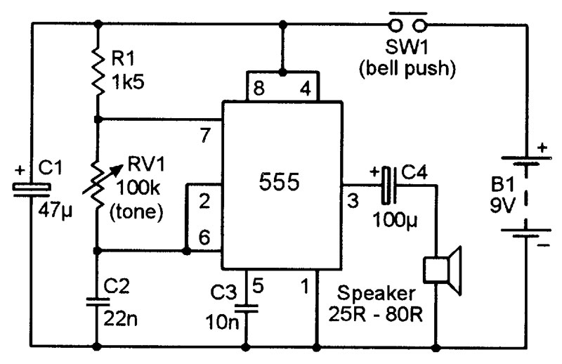
FIGURE 6. Electronic ‘door-buzzer.’
Figure 6 shows a simple electronic ‘door-buzzer’ that feeds a monotone signal to a small speaker (25R to 80R) when SW1 is closed; C1 has a low supply-line impedance and ensures adequate output drive capacity.
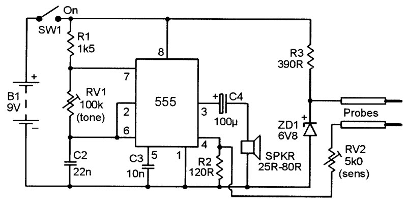
FIGURE 7. Continuity tester.
Figure 7 shows a continuity tester that generates an audible tone only if the resistance between the test probes is less than a few ohms. The astable operates only if pin 4 is biased above 700mV; normally this pin is grounded via R2, so the astable is off; to operate the astable, the two probes must be shorted together, connecting R2 to the output of the R3-ZD1 voltage-reference generator via RV2. In use, RV2 is trimmed so that astable operation is barely obtained under this condition, and ceases if the inter-probe resistance exceeds a few ohms. Note that the circuit consumes several mA whenever SW1 is closed, even if the probes are open circuit.
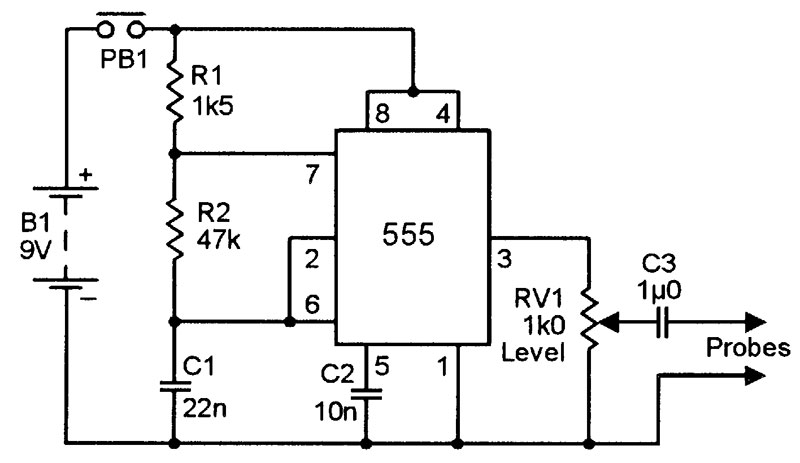
FIGURE 8. Signal injector.
Figure 8 shows a signal injector that is useful for testing both AF and RF circuits. The astable operates at a basic frequency of a few hundred Hz when PB1 is closed; the square output waveform is very rich in harmonics, however, and these can be detected at frequencies up to 10s of MHz on a radio receiver. The signal injection level is variable via RV1.
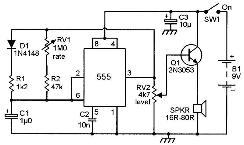
FIGURE 9. Metronome circuit.
Figure 9 shows a metronome in which the ‘tick’ rate is variable from 30 to 120 beats per minute via RV1, and the volume is variable via RV2. This circuit is a modified version of the standard astable, with its main timing network driven from the IC’s pin 3 output. When the output switches high, C1 charges rapidly via D1-R1 to generate a brief (a few mS) ‘tick’ pulse. When the output switches low again, C1 discharges via RV1-R2, producing an ‘off’ period of up to 2s (= 30 beats/minute). The output pulses are fed to a small speaker via volume control RV2 and buffer Q1.
LED FLASHERS and ALARMS
Figures 10 to 12 show the 555 astable used in LED flasher applications in which the LEDs have equal on and off times. With the component values shown, the circuits each operate at about one flash per second.
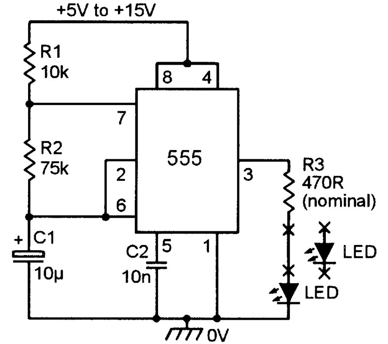
FIGURE 10. LED flasher with ‘single-ended’ output.
The Figure 10 circuit has a ‘single ended’ output. Either a single LED or a chain of series-wired LEDs can be put between the IC’s output and ground, and all LEDs turn on or off together; R3 sets the ON current of the LEDs. Most LEDs drop about 2V when on, so several LEDs can be series-wired in a circuit that is powered from a 15V supply.
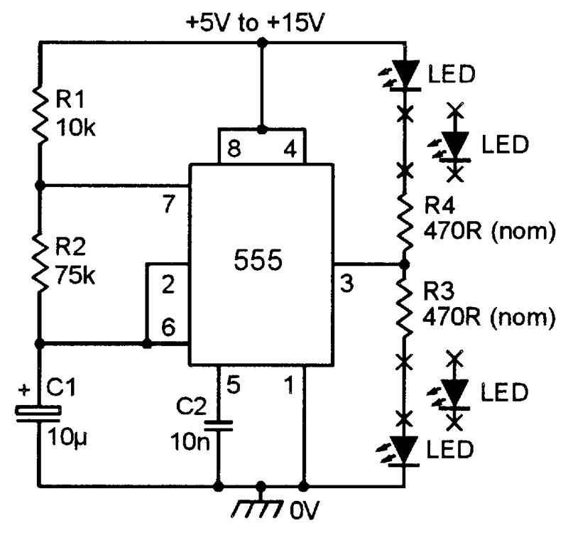
FIGURE 11. LED flasher with ‘double-ended’ output.
Figure 11 is similar to the above, but has a ‘double-ended’ output connection in which all ‘upper’ LEDs are on when the ‘lower’ ones are off, and vice versa. R3 sets the ON currents of the lower LEDs and R4 sets that of the upper ones.
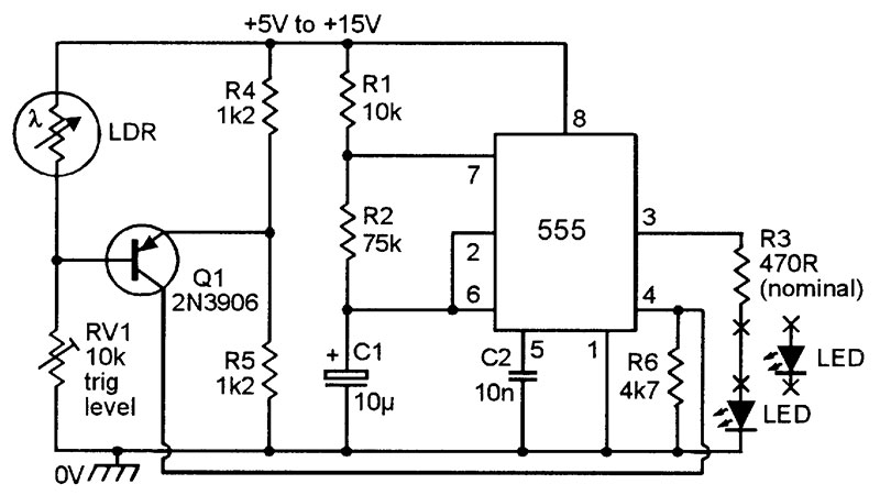
FIGURE 12. Automatic (dark-activated) LED flasher.
Figure 12 shows the basic Figure 10 flasher circuit modified to give automatic dark-activated operation. R4-R5-LDR-RV1 are used as a light-sensitive Wheatstone bridge that is used to activate the 555 astable via balance-detector Q1 and the pin 4 RESET pin of the IC. Under bright conditions, the LDR has a low resistance, so the Q1 base-emitter junction is reverse-biased and less than 700mV appear on pin 4, so the astable is off. But under dark conditions, the LDR resistance is high and Q1 is biased on, generating more than 700mV on pin 4 and turning the astable on. The LDR must give a resistance in the range 470R to 10K at the dark turn-on level, and RV1 is adjusted so that the astable just activates under this condition.
The above technique gives precision gating and can be used to auto-activate a variety of other 555 astable circuits, to make various audible alarms and relay pulsers, etc. By transposing the LDR and RV1 positions or replacing the LDR with an NTC thermistor, these circuits can be made to auto-active when light or temperature levels go beyond pre-set limits. Figures 13 to 15 show practical examples of such circuits.
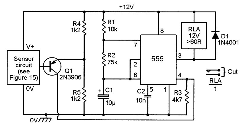
FIGURE 13. Heat/light-activated relay pulser.
The Figure 13 circuit gives automatic heat or light activation of a relay pulser, which switches on and off at a once-per-second rate when activated. The relay can be any 12V type with a coil resistance greater than 60 ohms, and its contacts can be used to activate external electrically powered devices such as light, sirens, or alarm horns, etc.
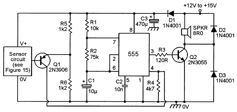
FIGURE 14. Heat/light-activated medium-power monotone (800Hz) alarm.
Figure 14 gives automatic heat or light activation of a monotone alarm-call generator, which generates an 800Hz alarm tone at several watts in an eight-ohm speaker when activated. Note that the high output current of the circuit may cause modulation of the supply line, so D1 and C3 are used to protect the circuitry from ripple effects, and D2 and D3 clamp the speaker’s inductive switching spikes and thus protect output transistor Q2 from damage.
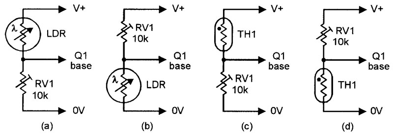
FIGURE 15. Alternative sensor circuits for use with Figure 13 or 14, to give activation via (a) dark, (b) light, (c) under-temperature, or (d) over-temperature.
Figure 15 shows the alternative sensor circuitry that can be used to auto-activate the Figure 13 or 14 circuits. For light-sensitive operation, the sensor must be an LDR; for temperature-sensitive activation, it must be an NTC thermistor; in either case, the sensor element must have a resistance in the 470R to 10K range at the desired trigger level.
LONG-PERIOD TIMERS
The 555 IC can be used to make an excellent manually-triggered relay-driving timer when connected in the monostable or pulse-generator mode, but cannot give accurate timing periods in excess of a few minutes, since it would have to use a high value electrolytic timing capacitor, and these have very wide tolerance limits (typically -50% to +100%) and large and unpredictable leakage currents.
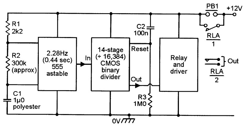
FIGURE 16. Method of obtaining 60-minute timing period from the 555 IC.
An excellent way of getting very long but accurate timing periods is shown (in block diagram form) in Figure 16, which outlines the design of a 60-minute relay-driving timer. Here, the 555 is wired as a 2.28Hz astable that uses a stable polyester timing capacitor, and its output is fed to the relay driver via a 14-stage binary divider that gives an overall division ratio of 16,384. The divider action is such that (if its output register is set to zero at the start of the input count) its output switches high on the arrival of the 8192nd astable pulse and goes low again on the arrival of the 16,382nd pulse, thus completing the count cycle. Thus, the Figure 16 circuit operates as follows:
The timing sequence is initiated by pressing push-button switch PB1, thus connecting the circuit’s supply, activating the astable, and (via C2-R3) setting the counter to ‘zero count’ and driving its output low and turning the relay on; as the relay turns on, its RLA/1 contacts close and by-pass PB1, thus maintaining the supply connection once PB1 is released. This state is maintained until the 8192nd astable pulse arrives, at which point the counter’s output switches high and turns the relay off, thus opening contacts RLA/1 and breaking the circuit’s supply. The operating cycle is then complete. Note that the astable operates with a period that is only 1/8192nd of the final ‘timing’ period, i.e., 0.44 seconds in this case, and that this period can easily be obtained without using an electrolytic timing capacitor.

FIGURE 17. Two-range (1-10 minute and 10-100 minute) relay-output timer.
Figure 17 shows the above technique used to make a practical relay-output timer that spans one minute to 100 minutes in two overlapping decade ranges. Here, the 555 variable-frequency two-range astable feeds clock pulses to the 4020B 14-stage divider which, in turn, activates the relay via transistor Q1. The circuit uses a 12V supply, and the relay can be any 12V type with two or more sets of change-over contacts and a coil resistance of 120 ohms or greater.
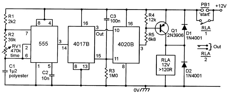
FIGURE 18. Extra-long-period (100 minutes to 20 hours) relay-output timer.
Figure 18 shows how the available time delay of the circuit can be further increased by wiring a 4017B decade divider between the output of the 555 and the input of the 4020B, to give an overall division ratio of 81,920, thus making delays in the range 100 minutes to 20 hours available from this single-range timer. Both divider ICs are automatically reset (via C3-R3) at the moment of switch-on (PB1 closure).
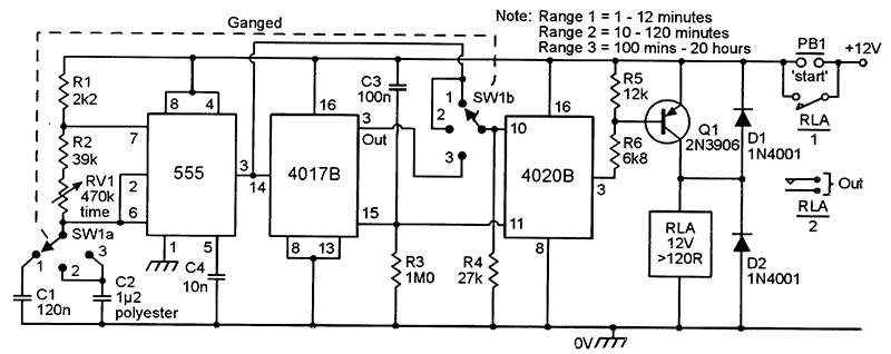
FIGURE 19. Wide-range timer that covers one minute to 20 hours in three decade ranges.
Finally, Figure 19 shows the above circuit modified to make a wide-range general-purpose timer that spans one minute to 20 hours in three decade-related ranges; the 4017B decade divider stage is used only on range ‘3.’ Range switching is obtained via two-pole three-way switch SW1. NV