Tube or not tube? Hams are still on the best of terms with “hollow state” electronics!
You might think the vacuum tube has burned itself out of electronics, but its filaments are still burning brightly in certain quarters. The very first electronic device capable of amplifying a signal — the vacuum tube or “valve” as it is known in the United Kingdom — was invented by John Ambrose Fleming (1905) and then enhanced by Lee de Forest (1906) during some heady years in physics.
This was the era of radioactivity, relativity, electromagnetic waves, and the quantization of energy — literally everything changed as our understanding of the physical world was revolutionized by a stream of discoveries and inventions. Today, however, the vacuum tube is largely extinct in electronics except for a few applications where it still works very well.
What Can a Tube Do Best?
Audiophiles and musicians — particularly guitarists — are well-acquainted with the technology; “tube amps” are still sought-after equipment. The sound of a vintage electric guitar blasting through an equally vintage tube “head” (turned up to 11, of course!) might well be the clarion of the 20th century’s latter half. Tubes still hold sway on stage and in an audiophile’s rack; not because of their fidelity, but because of the way they lack it!
A tube’s non-linearities color the amplified signal in ways that are pleasing to the human ear. Similarly, instruments themselves developed over the centuries to produce a sonic palette that humans like. The tube is well-suited to reproduce it, and so instruments and tubes and amplifiers all co-evolved into producing sound with spectral qualities we have grown to expect. Solid-state may have better looking specs on paper, but the ear knows what it wants! Expect tube amplifiers to be with us for some time yet.
Along with audio amplifiers, hams have relied on tubes since the 1920s when AM broadcast receivers created a huge market for them. Prices dropped and hams popped tubes into receivers and transmitters as quickly as new types were developed. Transmit power climbed from the early five watt designs to 100 watters.
By the onset of WWII, kilowatt “rock-crushers” were on the air. Military surplus flooded the market in the 1950s leading to the desktop-kilowatt. The tube was king!
Like the dinosaurs, tubes have not been outpaced by bigger devices but by tiny transistors, beginning with fragile point-contact devices and relatively crude (by today’s standards) junction diodes. The transistors kept getting bigger and faster until tubes are only found in today’s highest-powered applications where transistors just can’t go.
For hams, “steam radio” that glows in the dark is still the norm. However, with new pallet-style devices coming on the market, the tube “linear” is probably having its last great hurrah before becoming a legacy technology along with the modulation transformer and swinging choke.
Still, if you need to switch high voltage and high current, withstand crippling transients, or generate RF power in the megawatt range, you’ll be talking to the tube manufacturers.
Tube Basics
The foundation of all tubes is thermionic emission. Basically, that means heating a material (usually an oxide-coated wire or cylinder) to where it is so hot that free electrons can leave the atoms to which they are normally bound. These free electrons can move into a surrounding vacuum where they are free to travel in response to electric fields. This effect was originally discovered by Frederick Guthrie in 1873 and then again by Thomas Edison a few years later. However, it wasn’t until the turn of the century that the effect was put to work.
Each tube has at least two elements: the cathode from which the electrons are emitted; and the anode or plate to which the electrons travel. A positive voltage is applied from the cathode to the plate so that the negatively-charged electrons move from one to the other. This is electronic current as opposed to conventional current which you are probably more familiar with. (See the sidebar about the difference between the two.) The cathode itself can be heated by an electric current through a filament like a light bulb or indirectly heated by a nearby filament.
A two-element tube or diode (“two-electrode”) can act as a rectifier, which is basically a one-way current valve. Fleming’s diode was used mostly as a detector for RF signals by turning their AC current into a DC-plus-audio current that could produce audible sound.
It was de Forest who created the triode by adding a third element: a control grid in the space between the cathode and anode. By varying the voltage between the grid and the cathode, the flow of electrons can be controlled.
A positive voltage accelerates the electrons toward the grid but most miss its tiny wires and reach the anode, creating plate current, IP, through the tube. A negative voltage repels the electrons, reducing plate current; perhaps all the way to zero or cutoff if the voltage is high enough. Figure 1 shows a cutaway view of a triode with an indirectly heated cathode.
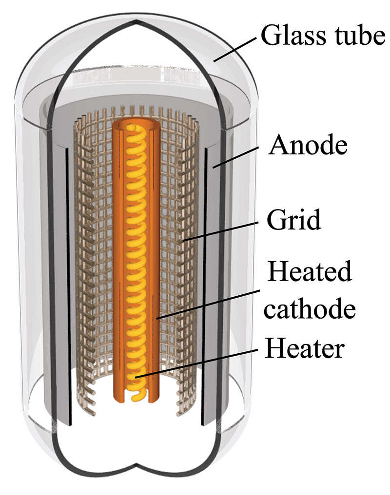
FIGURE 1. A cutaway drawing of a triode tube showing the filament heating the cathode, which is the source of electrons. The control grid surrounds the cathode and the electrons must pass through it on the way to the anode or plate. In a tetrode or pentode, there are additional grids between the control grid and the plate. (Graphic by Svjo (Own work) [CC BY-SA 3.0 (http://creativecommons.org/licenses/by-sa/3.0)], via Wikimedia Commons.)
Common tube types include tetrodes (two grids) and pentodes (three grids) which add screen and suppressor grids to manage secondary effects of the cathode-to-anode electron flow. Most high power transmitting tubes are triodes or tetrodes. The audio tube amp’s most common tube is some variation on the classic 6L6 power-beam pentode. Figure 2 shows the schematic symbol for a tetrode.
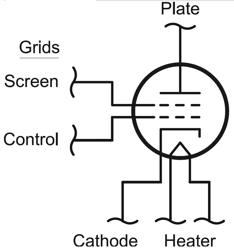
FIGURE 2. The symbol for a tetrode vacuum tube is very similar to a pictorial of how the tube is constructed. This symbol shows an indirectly-heated cathode, electrically isolated from the filament or heater. (Graphic courtesy of the American Radio Relay League.)
Conventional and Electronic Current
Many years ago, during the early years of electrical experimentation, the assumption was made that electrical current was the flow of positive charges. A polarity had to be assumed and there were just two choices. Unfortunately for engineering and physics students, the wrong one was chosen as current in circuits is really the flow of negatively-charged electrons. (This mistake is often attributed to Ben Franklin, but there were others who guessed wrong too.) Electronics generally uses conventional current which flows from positive to negative voltages.
Thus, electronic people think of current somewhat differently than physicists, and this causes no end of confusion — particularly with the direction of magnetic fields created by electric current. (See the Wikipedia entries for right-hand rule and left-hand rule for an illustration.) Nevertheless, conventional and electronic current are equivalent except for the assumed polarity of the charge-carrying particles.
Tube Action
There are many similarities between the vacuum tube triode and the solid-state field-effect transistor, or FET. In particular, the tube acts somewhat like an N-channel depletion-mode JFET or MOSFET. As grid-to-cathode (gate-to-source in the FET analog) voltage, VG, increases, so does cathode-to-anode (source-to-drain) current. There is no “P-type” vacuum, of course! (Tube voltages such as VG and VP are assumed with the cathode as the reference.)
Each of the characteristic curves on the graph in Figure 3 shows the behavior of IP at different grid voltages.
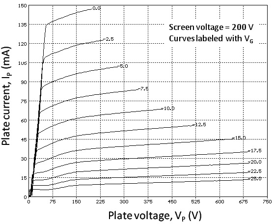
FIGURE 3. Characteristic curves for a 6L6 vacuum tube. Each individual curve shows the plate current versus plate-to-cathode voltage for one value of the grid-to-cathode voltage. This tube is commonly used in audio amplifiers.
The top curve shows that with VG = 0, there is plate current. As VG becomes more negative, the current curves flatten out at lower values of IP. This creates a linear region in which a change in VG (such as from an audio or RF input signal) creates an equivalent but larger change in IP. Thus, we have an amplifier. The basic circuit for a triode amplifier is shown in Figure 4.
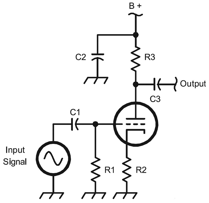
FIGURE 4. Simple schematic for a triode amplifier. C1 and C3 are DC blocking capacitors to isolate the AC input and output from the DC operating voltage on the grid and plate. R1 and R2 are the grid and cathode bias resistors, respectively. The bias voltage is developed by current flowing from the electrode to ground. R3 is the plate bias resistor, and also sets the amplifier gain. (Graphic courtesy of the American Radio Relay League.)
The different curves in Figure 3 show that what matters to controlling the tube’s plate current, IP, is the voltage between the grid and cathode, VG. A vacuum tube acts as a voltage-controlled current source, or VCVS. Like the FET, the relationship between the control voltage and resulting current is expressed as transconductance — gm = Ip / VG — and has the units of siemens (S) which are amps per volts; more often given as mS, which are mA per volt.
The gain — μ or mu — of the tube depends on the circuit. For the triode circuit in Figure 4, μ = –gm / RP. The minus sign indicates that the output waveform is inverted. That is, when input voltage increases causing an increase in IP, the output voltage drops because of the higher current flowing through the plate resistor, R3.
The Full Gallon
That’s the colloquial name for the full legal limit on output power for US amateurs: 1,500 watts. (The reference comes from before the “modern era” when power limits were stated in terms of the DC input power to the amplifier; back then, the limit was 1 kW. The slang term for kW was “gallon,” so there you are.)
Until fairly recently, the only economical way of generating that much power was by using big vacuum tubes — both physically large and electrically outsized.
The typical amateur amplifier produces from 600 to 1,500 watts with one or two tubes. Construction varies from custom homemade units to top-quality commercial models.
Amplifier building is common since it doesn’t take special tools or techniques. You can build a perfectly good amp with hand tools, and many hams have done just that.
The most popular tubes for HF builders are the venerable 811 (developed in the late 1930s and still used commercially for RF and audio), the 3-500Z triode, and the 8877 tetrode which is often available as a “pull-out” from commercial equipment. A browse through a ham radio equipment dealer’s website will show there is plenty of interest in full power operation.
Figure 5 shows the result of a project by John Stanley K4ERO to design a simple amplifier that could use inexpensive components — even a microwave oven transformer — in various configurations: The Everyham’s Amplifier.
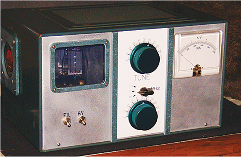
FIGURE 5. The “Everyham’s Amp” by John Stanley K4ERO. Designed to use parts on-hand and available used or from surplus outlets, the HF amplifier can be built to use many common tubes, and produce power from a few hundred watts to more than 1 kW of output power. (Photo courtesy of the American Radio Relay League.)
Stanley designed the circuit so that almost any large tube (or tubes) available could be used, including some Russian military surplus tubes from amplifiers used in tanks. All the parts can be found in old amplifiers, at hamfest flea markets, or scrounged from friends.
Figure 6 is an example of what a skilled builder can do. This full power design is for use at 50 MHz.
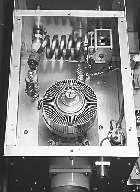
FIGURE 6. This beautiful example of home construction by Dick Stevens W1QWJ produces the “full gallon” on the 50 MHz band. The single tube is a 4CX1600B tetrode. High power on VHF and UHF frequencies requires great care in design and construction because of the short wavelengths involved and sensitivities to “stray” capacitance and inductance. (Photo courtesy of the American Radio Relay League.)
If you like the looks of these projects, there are plenty of amplifier and suitable power supply projects in the pages of the ARRL Handbook starting with editions from the 1950s. There is lots of tube theory and design information in those old books.
If you can find a copy of the RCA Transmitting Tubes manual, that too is a great source of information. The ARRL’s “Building Equipment” page (www.arrl.org/building-equipment) is also a wealth of information, projects, design tutorials, and links to websites about tubes — good stuff!
Really High Power
If you want to start talking about really high power at really high frequencies, there are a couple of vacuum tubes you should really meet: the klystron and the magnetron. In fact, you probably have a small example of a magnetron heating your dinner in the kitchen. However, that’s a little tube compared to the really big ones in use at broadcast TV stations and particle accelerators, to name two places they are found.
The klystron (en.wikipedia.org/wiki/Klystron) in its most basic form shoots an electron beam from a cathode through a resonant cavity. Microwave RF input into the initial cavity causes the beam to accelerate and decelerate. This, in turn, causes the electrons to form groups, which is why this cavity is called the “buncher.” The groups of electrons continue to travel or “drift” through a tube in which the grouping gets stronger.
At the other end of the tube is a second resonant cavity that extracts energy from the beam as RF at a frequency determined by the beam’s velocity and size of the groups. Figure 7 shows a high power klystron in use at the Fermilab accelerator in Batavia, IL. Top to bottom, the water-cooled tube is about 12 feet high!
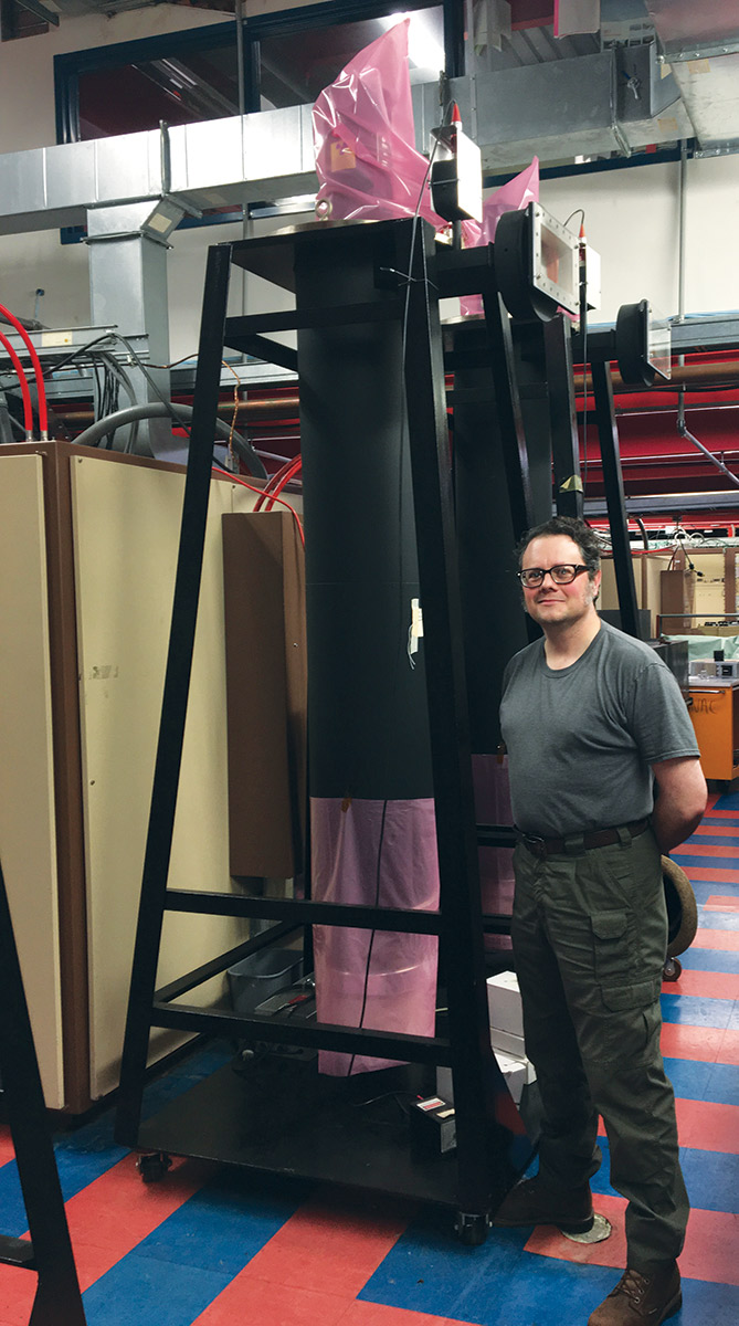
FIGURE 7. A pair of large Litton L5859 klystrons in use at the Fermilab Linac particle accelerator (www.fnal.gov). Matt Domeier of the Fermilab High-Level RF Group is shown next to the tubes to give an idea of how big they are. Through the waveguide window, each tube delivers 5 MW at 805 MHz in 200 microsecond pulses at a 15 Hz repetition rate. Many of these klystrons transfer energy to the particle beam in order to accelerate it to near the speed of light. (Photo by Kermit Carlson W9XA, Fermilab.)
Cousin to the klystron, the magnetron also uses a resonant cavity to excite electrons at microwave frequencies. The magnetron is strictly an oscillator, however. It can’t amplify signals.
The magnetron (en.wikipedia.org/wiki/Cavity_magnetron) consists of a circular hole through a block of metal which acts as the tube’s anode. The cathode is in the middle of this hole. The hole is surrounded by resonant chambers formed in the block of metal, which is usually copper. A strong field from permanent magnets causes the electrons from the cathode — which is at a high negative DC voltage compared to the grounded anode — to take a semi-circular path. The radiation from the electrons excites current flow in the resonant cavities, creating a strong RF field. The RF is extracted from the cavities by coupling loops where it is used to create a radar pulse or to pop popcorn!
A large magnetron with a special history is shown in Figure 8.
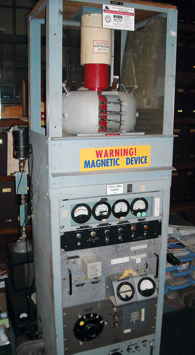
FIGURE 8. On display at the station of W5ZN, this magnetron was used to make some of the first amateur radio Earth-Moon-Earth (EME or “moonbounce”) contacts on the 2.3 GHz band in 1970 between W4HHK and W3GKP. The permanent magnets are the gray assemblies around the red vacuum tube portion of the magnetron. RF output came out of the white assembly at the top. Several hundred watts of microwave (UHF, technically) power in 1970 was quite an achievement!
What is the Tube’s Future?
That is an excellent question! Although I don’t think digital signal processing (DSP) and software defined radio (SDR) are going to be able to generate much high power RF, big transistors with integrated protection circuits are rapidly taking over niches previously filled by tubes.
At the high end of the energy scale, tubes remain supreme but possibly not for long. I think there will always be some special tube that is the only solution to a special problem. Maybe their ability to tolerate faults and high voltages will keep them on the job where solid-state devices would fail. Time will tell, but the vacuum tube has a lot of life left in its filaments! NV
High Voltage Safety
The following 10 items of advice from veteran builder, Jim Garland W8ZR are adapted with permission from the newly-released 2018 edition of the ARRL Handbook and apply to any project involving high voltage — whether tube circuits or some other project.
We are all besieged these days with verbose safety warnings on mostly harmless consumer goods and have become accustomed to solid-state circuits in which we seldom encounter any AC voltage higher than 12V. It’s easy to forget that some things really are dangerous, and high voltage is one of them.
- Don’t let your reach exceed your grasp. High voltage is not for beginners.
- Working with high voltages requires the maturity and patience that comes with age and experience. If you are a young builder, work with an experienced mentor.
- Never work around high voltage when you are tired, stressed, or in a hurry.
- Never work around high voltage after drinking alcohol. Even one beer or glass of wine can impair your judgment and make you careless.
- Before working on a high voltage power supply, always follow these three steps: Unplug the AC power cord; discharge any energy storage or filter capacitors; and verify that the voltage is truly zero. A time-honored practice is to use a “chicken stick” (a wooden dowel or PVC tube, with one end attached to a grounded wire) to make sure filter capacitors are completely discharged.
- When working on a high voltage power supply, remember that a dangerous time is after the power supply has just been turned off, but before the filter capacitors have fully discharged. A 50 µF capacitor charged to 4,000V holds a potentially deadly 400 joules of energy. Even with bleeder resistors, it can take a minute or more to discharge fully.
- When removing a recently discharged filter capacitor from a power supply, tie the two terminals together with wire. Large high voltage capacitors can self-charge to dangerous levels if the terminals are left floating.
- Don’t stake your life on the expectation that bleeder resistors, fuses, circuit breakers, relays, and switches are always going to do their job. Even though modern components are very reliable, it is safe practice always to assume the worst.
- Don’t build high voltage circuits if you don’t understand how the circuit works. High power amplifiers and power supplies are not “plug-and-play” projects with step-by-step instructions. Builders must be knowledgeable enough to improvise, make component substitutions, and implement design changes.
- With high voltage projects, it doesn’t pay to be “penny wise and pound foolish.” Use high quality components throughout.