Electronics hobbyists evolve through a series of circuit-building techniques, starting with the simplest of the simple, such as wire nuts or twisting component leads together, to designing, fabricating, and assembling their own printed circuit boards.
After successfully building a few simple circuits on perf board, and perhaps a small kit or two, confidence rises. They find it's time to move on to bigger and better circuits.
The neophyte soon finds out that assembling a more complex circuit onto perf board is an exercise in futility. Part way into the project, too many connections too close together turn it into an unmanageable mess.
Construction articles found in electronics magazines use printed circuit boards for all but the simplest circuits, so investing time and money into the PC board fabrication process seems to be the next logical step, albeit a bit daunting for the new hobbyist. PC board fabrication is not necessarily the next step.
There is another alternative … wire wrap.
It's relatively fast, reliable, simple, solderless, inexpensive, and easy to learn. Wire wrap has been successfully used for decades by the telecom/datacom and controls industries. It is ideal for complex one-of-a-kind circuits and systems. Nimble-fingered production assemblers, armed with pneumatic wire wrap guns, an assortment of pre-stripped wires, and computer printouts of wiring charts, are amazingly fast and accurate. A system back plane with thousands of wire terminations is typically completed in a few days.
WHAT IS WIRE WRAP, ANYWAY?
Simple; it's a wire connection system that uses a special tool to tightly wrap a small gauge solid wire around the sharp corners of a connection post. Bell Telephone Laboratories developed the system, and OK Industries, which was founded in 1946, pioneered the process.
Wire wrap has been around a long time. OK Industries remains one of the leading industrial suppliers of wire wrap tools and supplies.
RELIABILITY
See Figure 1. By bending the wire around the sharp corners of a square post, the oxidation on both the wire and the terminal is crushed or sheared, and a clean, oxide-free metal-to-metal electrical connection is obtained.
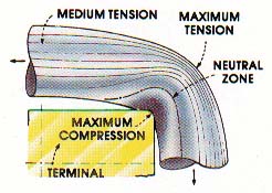
FIGURE 1 — MECHANICS OF A WIRE WRAP This enlarged cross-section of a wire wrap connection shows the maximum force occurs where the wire is wrapped around the sharp corner, which crushes and shears the oxide layers, thus creating a clean, gas-tight metal-to-metal contact.
The contact point between the wire and the post is gas-tight. This means the contact is tight enough to prevent the intrusion of air, and thus eliminating the possibility of any oxidation occurring between the contact surfaces.
Wire wrap is also very stable when exposed to temperature changes, corrosive atmospheres, humidity, and vibration. It is stronger than a solder connection. It is less easily stripped from the terminal, and is less subject to breakage. The connection can be removed quickly and easily, with no damage to the terminal.
TYPES OF WRAP
See Figure 2. The regular wrap coils only the stripped portion of the wire around the post. This style is quite adequate for most applications.
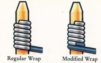
FIGURE 2 — TYPES OF WRAP A “regular” bit wraps the bare wire only around the post. A “modified” bit wraps a portion of the insulation around the post in addition to the bare wire. This greatly increases the ability to withstand vibration.
The modified wrap coils a portion of the insulation around the post, as well as the stripped section. This gives better vibration protection, as well as provides an extra bit of wire if the connection needs to be moved to another post during troubleshooting or circuit revision.
TOOLS
Hobby Hand Wrap/Unwrap Tools. See Figure 3. This is the best place to start. OK Industries’ tool WSU-30 (regular wrap) is shown. The WSU-30M (modified wrap) tool looks almost identical. The wrap and unwrap bits are installed on opposite ends of the handle, and a 30 AWG wire stripper is built into the center of the handle.
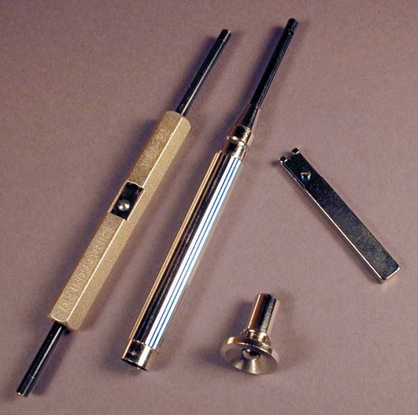
FIGURE 3 — HOBBY HAND WRAP/UNWRAP TOOLS The tool on the left is an OK Industries #WSU-30; the wrap and unwrap bits are on each end, and the wire stripper is attached in the center of the handle. The tool on the right is from RadioShack. The same bit is used for wrapping and unwrapping. The cap is shown removed. The wire stripper that is stored inside the handle is shown on the extreme right.
Powered and Manual Wrap-ping Tools. See Figure 4. The unit shown is an OK Industries’ 115 VAC tool. Several models and options are available There are also battery-powered tools available, as well as a manual tool with a squeeze-ratchet mechanism that spins the bit. The battery-operated and squeeze tools are very often used by field service people who don't always have convenient access to plug-in power at a job site. The bits and bit sleeves are sold separately for different types of wraps and different gauges wire. These tools require a small investment, so the hand tools should definitely be tried first to determine if wire wrap is the way to go.
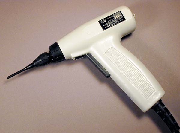
FIGURE 4 — WIRE WRAP GUN This is an OK Industries wire wrap gun that is powered by 115 VAC. The bit and sleeve are held on by a hand-tightened chuck, and are quickly and easily replaced for different types of wrap and different gauges of wire.
Wire Strippers. Chances are that a regular old toolbox stripper won't work. Wire wrap requires 30 AWG solid wire with a special thin insulation. A universal V-notch stripper will nick and weaken or break the wire, and better strippers rarely strip wire that small. There are dedicated wire wrap strippers for industrial applications, but they're rather expensive, and most are not readily available through consumer distributors. The best bet is the stripper that comes with, or is built into, the hand wrap/unwrap tools or wire dispensers.
WIRE
Wire wrap wire is 30 AWG solid wire, with a special thin insulation, usually Kynar™ or Tefzel™. It is sold by the roll, or by pre-stripped lengths, or in an OK Industries dispenser that cuts and strips rolled wire in one operation. The wire comes in an assortment of colors, and is carried by many distributors. Wire sizes other that 30 AWG are not available from most consumer distributors, and are usually special-order items for industrial applications.
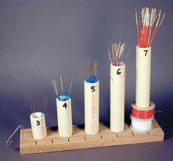
FIGURE 5 — PIPE ORGAN This is a homemade bench top holder for pre-cut/pre-stripped wires. It’s made from lengths of plastic water pipe glued into counterbored holes in a piece of wood. Inch marks on the wood help to measure spooled wire, which is conveniently stored on the end pipe. The safety pin is used to straighten “unwraps.”
Pre-cut lengths of wire wrap wire with 1" stripped ends are available from Digi-Key. These cost a bit more, but they cut about a third or more off the assembly wiring time. See Figure 5 for a do-it-yourself wire holder.
MAKING THE CONNECTION
See Figure 6. A wire wrap connection requires a 1" long stripped end of wire.
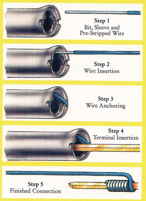
FIGURE 6 — MAKING THE CONNECTION The wrapping bit shown is on a power tool. A hand tool is very similar, except it doesn’t have the two notches on the outside lip of the sleeve. It’s a simple procedure that takes a few seconds per connection.
The execution of a wire wrap connection is pretty much the same for a hand tool as it is for an electrically- or manually-powered tool. The difference is that a with a hand tool, the wrapping bit is twirled by hand, and with a power or manual tool, the bit is spun by a motor, or a mechanical squeeze-ratchet mechanism.
There are two holes in the end of a wrapping bit. Insert the stripped end of the wire into the hole that is closest to the outside diameter of the bit. This is the smaller of the two holes. When the inserted wire bottoms in the hole, bend it outward, and place the larger center hole over the wire wrap post.
Hand Tool. Hold the free end of the wire so it doesn't turn when the bit is turned. Twirl the tool clockwise with the fingers, and when turning resistance is no longer felt, the wrap is complete. Lift off the tool.
Power Tool. After inserting the stripped wire into the bit, anchor the free wire end by bending it back through one of the two notches on the lip of the sleeve. Place the bit over the post, and against the board. This will anchor the wire and keep it from turning when the bit turns. If the connection is higher on the post and away from the board, the free end of the wire will have to be held to keep it from turning. Press the trigger for about a second or so until the wrap is complete. Let the power tool do the work. There is no need to press down. Just guide it.
Learning to wire wrap is no more difficult than learning to solder properly. A few practice connections will probably be necessary to get the feel of the tool, and to develop "the knack." Again, like soldering, dexterity and speed increases with experience.
GOOFS AND PROBABLE CAUSES
Overwrap. See Figure 7a. Too much downward pressure on a power tool during wrapping usually causes this. Again, let the tool do the work. Many OK Industries power tools have a feature to help prevent this, and it is indicated by a "BF" (backforce) suffix in the part number. It costs a little more, but is recommended.

FIGURE 7a — OVERWRAP PROBLEM Usually done with a power tool by applying too much downward pressure. Let the tool do the work. Just guide it.
Open Wrap/Spiral Wrap. See Figure 7b. This is another power tool problem, and is caused by removing the tool before the wrap is complete. Leave it on the post a wee bit longer. Don't remove the tool before the motor stops.
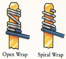
FIGURE 7b — OPEN WRAP & SPIRAL WRAP PROBLEMS Caused by removing the power tool before the wrap is completed. Leave the tool in place a bit longer.
Insufficient Turns. See Figure 7c. Caused by not inserting the stripped end of the wire into the bit all the way.

FIGURE 7c — INSUFFICIENT TURNS PROBLEM Caused by not inserting the stripped end of the wire far enough into the wrapping bit.
Loose Wrap/Pigtail. See Figure 7d. Usually caused by a mismatch between the wire size and the tool bit. Hobby hand tools are for 30 AWG wire only. Power tools require a different bit and sleeve for each size wire used.
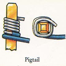
FIGURE 7d — LOOSE WRAP/PIGTAIL PROBLEM Wire wrapping is a precision technique, and the wrong tooling cannot do the job. If bits and sleeves or hand tools do not agree with the wire size, a multitude of problems can occur.
FIXING GOOFS AND WIRING ERRORS
The easiest fix is to snip the wire off close to the post, and leave it there. Re-strip and re-install the snipped end of the wire, or toss it, and install a new wire.
Unwrapping a wire from a post is simple, fast, and easy. Simply place the "unwrap" bit over the post, and slowly turn counterclockwise. A slight downward pressure on the tool may be required to get it to "grab." Continue to turn until the wrapped wire "lets go." Lift off the tool; the wire may or may not come with it. If it doesn't, the wire will be loose enough to lift off the post, without further unwrapping.
The stripped end of an unwrapped wire can be straightened and re-used, with a little care and a trick or two.
After a successful unwrap, and with the wire free of the tool, the stripped end of the wire will be a tiny formed coil. The first tendency is to straighten it with a thumbnail. This will most likely kink and break it. Instead, insert the pointed end of a large pin into the coil, and then pull it straight (one of Aunt Fannie's hat pins, or a large safety pin will do). See Figure 8.
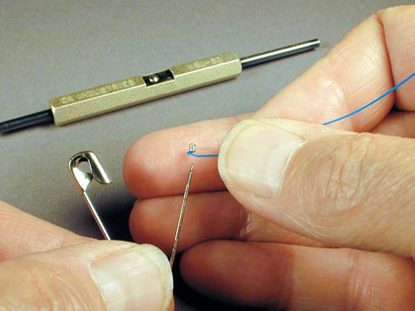
FIGURE 8 — RE-USING AN UNWRAPPED WIRE An unwrapped wire is a small coil. Insert a pin into the coil and pull it straight; straighten it further with a thumbnail, or roll it over the side of the pin. Snip about 1/16” from the tip to make it easier to insert the wire into the wrapping bit. Re-wrap as required.
The straightening can now be completed with a thumbnail, or by drawing it over a rounded edge. After straightening, snip about 1/16" from the end. There will be a tiny, almost invisible hook on the tip, which will make it difficult to re-insert into the wrapping bit.
The unwrapped end can now be re-wrapped. A hand tool re-wrap is usually most successful. Be gentle.
If the wire is still inside the tool after unwrapping, insert the pin into the unwrap bit center hole, and jiggle the tool a little (like a toilet handle) and lightly tug on the wire. The coil should come out of the tool intact, and still be on the pin. Straighten the wire and clip the tip as described above.
SO, WHAT'S TO WRAP?
Most wire wrapping is done on connectors. Industrial system back planes that were mentioned previously consist mostly of PC board edge connectors — quite often hundreds of them. These connectors are wired together configuring the system, and dedicated-function PC boards are plugged into the connectors, completing the circuitry.
Hobbyists use mostly DIP (dual in-line package) integrated circuit sockets. See Figure 9. This does not, however, limit one to using ICs only. There are many components that are available in DIP packages. Read on!
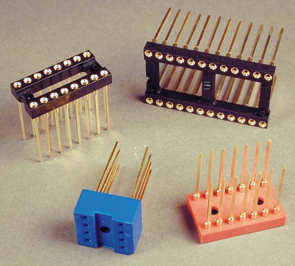
FIGURE 9 — WIRE WRAP DIP SOCKETS Typical integrated circuit wire wrap sockets available from most electronics distributors. Wire wrap connectors also include SIP sockets and male pin headers.
Wire wrap sockets are quite often specified as two or three level. See Figure 10. This simply means that the wire wrap posts can hold a maximum of either two or three wire wrap connections; the three level is a longer post (about 1/2"). The three level gives a little more versatility when routing and wiring the circuit.
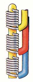
FIGURE 10 — WIRE WRAP SOCKET LEVELS Wire wrap sockets are defined as two or three level. A three level is shown above, and simply means the posts are long enough for three wire wrap connections. A two level post is a little shorter, and can only support two connections.
Other wire-wrappable connectors include male pin headers. SIP (single in-line package) connectors are also available. Individual wire wrap pins can be pressed into a project or perf board in any desired configuration.
THE ANATOMY OF A WIRE WRAP PROJECT
Most of the wire-wrappables used by the hobbyist will be 8-, 14-, and 16-pin DIP IC connectors as previously shown in Figure 9. An occasional SIP socket and male pin header may also be used. This does not mean, however, that one is limited to using mostly DIP ICs. Since these sockets have become electronics standards, there are now many components other than ICs that use DIP and SIP sockets. They include:
- Resistor Arrays
- LED Seven-Segment Displays
- Transistor Arrays
- Electro-Mechanical Relays
- Crystals and Oscillators
- Solid-State Relays
- Opto-Isolators
- Reed Relays
- LED Light Bars
- Diode Bridges
- Trim Pots
- Switches
- Ribbon Cables With DIP or
- Header Connectors
Of course, any electronics home hobbyist worth his (or her) salt will first head for the primary parts source … the junk box under the workbench. Chances of finding components in DIP packages here (other than ICs) are probably bleak. With a little adaptation and ingenuity, those radial and axial lead components, including big clunky capacitors, as well as semiconductors, can be wire wrapped.
Wire wrap sockets can, of course, be mounted onto any perf board having 0.1" hole spacing. A better choice, however, would be project board. A project board is similar to perf board, except it has printed circuit foil pads around each hole. This allows the sockets to be tack-soldered and secured to the board before connecting any wires. Wiring is much easier if the parts aren't wobbling and falling out of the board. DIP sockets can be secured by tacking the four corner posts to the project board. Gluing in place before wiring is another option.
Small components can be mounted on plug-in headers, as shown in Figure 11.
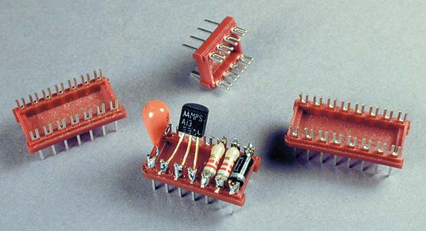
FIGURE 11 — PLUG-IN HEADERS These are ideal for mounting small components; they are available in many pin configurations, and plug into standard DIP sockets. Snap-on covers for the headers are also available.
Larger components can be mounted as shown by the blue capacitor in Figure 12. Insert the component leads through the project board, and tack-solder in place. Don’t clip the leads off flush, but rather leave about 1/4" or more protruding. Make the wire wrap connections to these component lead extensions. Hand-wrapping seems to work better with round leads. Since wire wrap is designed for posts with sharp corners, and the component leads are round, secure the wire wrap connection with a drop of solder for added reliability.
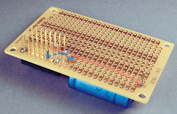
FIGURE 12 — MOUNTING LARGE COMPONENTS Components such as the blue capacitor above can be installed by inserting the leads through holes in the project board, and soldering to the PC foil pads around the holes. Leave the component leads on the foil side of the board about 1/4” long. Wire wrap to these leads, and tack with a drop of solder.
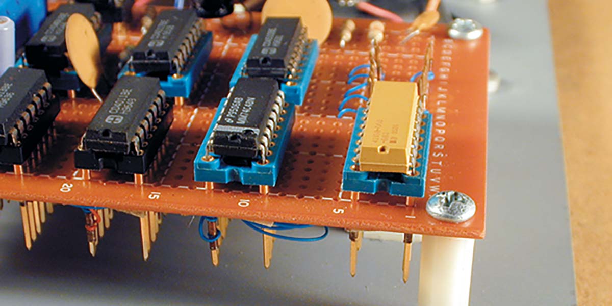
The wiring side of a completed wire wrap project is shown in Figure 13. Push the routed wires down against the board to make a neater looking project. The eraser end of a new wooden pencil makes the ideal tool to push the wires down between the IC socket pins.
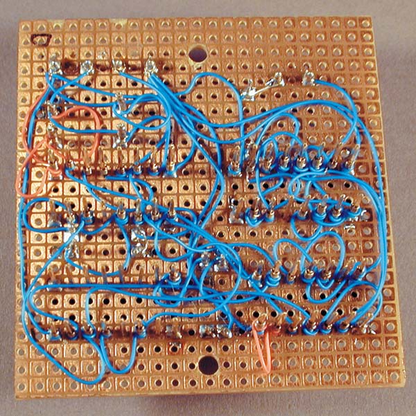
FIGURE 13 — COMPLETED WIRE WRAP BOARD The wiring lies neatly against the board and is routed with sufficient slack. The six top connections are a feed-thru terminal block, and are soldered, not wire wrapped.
A completed wire wrap board can be mounted into a chassis or a case any number of ways, as long as the wire wrap posts projecting from the back side aren't crushed or shorted. Standoff mounting as shown in Figure 14 is as good a way as any.
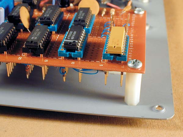
FIGURE 14 — WIRE WRAP BOARD MOUNTING Circuit boards can be mounted in chassis or case any number of ways. It is not critical. The method shown above uses standoffs that are long enough to provide clearance between the wire wrap posts and the chassis; 5/8” or longer will give clearance to a level three connector.
The board can also be mounted on spacers, angle brackets, or long screws and nuts. Some project cases have built-in card guide slots, which allow the project board to be mounted on edge.
RULES OF THUMB
- Avoid stringing wires “banjo string tight.” This puts an undue strain on the wires, connections, and posts. It is unreliable.
- Leave enough slack in each wire to allow for a re-strip and re-wrap if the circuit needs modifying. It may save a little work later.
- If a pre-stripped length of wire looks like it will be just long enough, it won't be. Use the next longer size.
- Route the longest wires first, and the shortest last. The short wires will hold the longer wires down against the board, making a neater looking assembly.
CONCLUSIONS
Wire wrap is not a replacement for soldering or for PC boards. It simply makes point-to-point wiring manageable.
Occasional solder joints will always be necessary.
Although a short run of 30 AWG wire can carry up to an amp, higher currents will require a heavier gauge wire soldered in place. A wire wrap onto a round component lead will also require a drop of solder for reliability.
Printed circuit boards, of course, are ideal for making multiple identical circuits, but are a lot of work for one circuit assembly. Granted, they do make a more "professional" looking assembly, but most of the time, the circuit is mounted inside a case or chassis anyway.
Wire wrapping is an assembly technique that is often overlooked by the home hobbyist.
A little practice and a nominal investment will allow the hobbyist to add this new tool to the old "bag o' tricks." NV
Color illustrations (except photos) are printed with the permission of OK Industries.