The original modes used by hams were intended for “human copy” in that the information was meant to be understood by a human listening to the receiver’s audio output. Even the initial “spark” (imagine turning a Tesla coil on and off with a Morse code key and you get the idea) was received by ear. The spark was “chopped” by a rotating wheel with contacts on it. Turning the spark on and off at a rate in the low audio range (less than 1,000 Hz) made the hiss of the radio spark audible as a tone.
In the Shack
Spark transmitters used high voltage arcs which were not only dangerous, but made one heckuva racket. The noise, fire hazard, and smells of ozone and various burning things (sounds like fun, doesn’t it?) caused the transmitter to be frequently banished to a backyard garage or shed for safety and sanity.
This resulted in the term “radio shack” which is still the slang today for a ham’s station — no matter how neat and tidy. Yes, that’s where the store’s name came from!
Human copy was the norm as CW (from “continuous wave”) displaced spark. Then, the voice modes of AM, FM, and SSB (see the previous column) were introduced. Most ham radio is conducted by one of these modes even today. However, the times, they are a-changin’.
Digital modes — according to the Federal Communications Commission (FCC) — are those that exchange information as characters. More accurately, the FCC distinguishes between data modes and radioteletype, or RTTY (pronounced “ritty” by hams; see en.wikipedia.org/wiki/Radioteletype). In data modes, characters are exchanged by computers (including microprocessors or other digital gadgets) and might represent a file, a message, telemetry, command characters, or something similar. RTTY, on the other hand, is a special data mode — the original!
RTTY, Our Digital Ancestor
RTTY is formally defined as direct-printing telegraphy because of its origins as an electro-mechanical system that connected keyboard-like contraptions over a telephone line or radio link. The bits of each character are encoded as a pair of tones for transmission. The receiver audio is then turned into printed characters by the teleprinter. (There’s more to it, but a complete explanation would take at least one whole article!) Teletype — now a generic term for the mode — was actually the name of the Teletype Corporation (en.wikipedia.org/wiki/Teletype_Corporation).
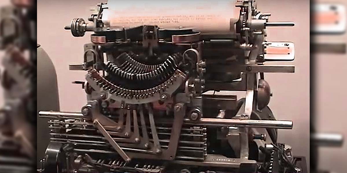
The first working teleprinter was developed in 1908, but the radioteletype system really came into wide use in the 1930s. Without making this into too much of a history lesson, the Teletype Model 15 was the PC of its day. Its maze of solenoids and levers was the pre-electronic equivalent of a UART and terminal. If you’ve ever seen one running, it’s unforgettable.
“How the Teleprinter Works” (above) is a 1940 tutorial about these mechanical marvels and a video of a working Model 15 that was in service for more than 50 years can be seen online below.
There is something very cool about watching a teleprinter over the Internet!
Many terms used in digital communications today — baud, mark, and space are just a few — came from the world of radioteletype. Baud (the number of symbols transmitted per second) is named for Baudot, who invented the five-bit code used to encode characters. Mark and space refer to the bits of the code. Start and stop were the synchronization intervals between characters, and so forth.
RTTY was the direct precursor to all of today’s digital communications and many veteran programmers used teleprinters — particularly the Model ASR 33 — to communicate with mainframes “back in the day.” Hams adapted surplus teleprinters to deploy amateur radio’s first digital mode in the post-WWII era. The mechanical units were eventually replaced with electronic display terminals, then microprocessor based systems, and finally the PC and sound card to send and receive the world’s oldest digital mode.
RTTY may not be the most robust in terms of error rate and it’s certainly not the fastest, but it’s simple and easy. Anyone can listen in to the conversation and it doesn’t require special or proprietary equipment. RTTY is closing in on its first century and it will probably be around for quite a few more years.
Frequency-Shift Keying (FSK)
The two tones used by RTTY are a type of modulation known as frequency-shift keying or FSK (en.wikipedia.org/wiki/Frequency-shift_keying). In FSK, shifts in frequency are the signaling event and the period during which a tone is transmitted is the symbol. There are several common methods of modulating a carrier to create FSK:
Shifting the frequency of an RF oscillator back and forth.
Modulating an SSB transmitter with tones instead of speech.
Modulating an FM transmitter with tones instead of speech.
On the air, methods 1 and 2 sound exactly the same. An unmodulated carrier and a sideband created by a single tone are identical signals. Method 3 creates a standard many-sidebands FM signal, but the audio output from the receiver sounds the same as the audio from methods 1 and 2.
Method 1 is called direct FSK because the RF carrier frequency is controlled directly by the digital data signal input to the transmitter. Methods 2 and 3 are called audio frequency-shift keying or AFSK because the digital signal is used to create an audio signal (the tones) that modulates the transmitter. The end result of all three is a set of tones that represent the 1/0 of a digital signal.
RTTY uses a pair of tones (mark and space, mentioned earlier), so it is binary FSK. The difference between the two tones is called the shift. Most ham radio RTTY on the HF bands (shortwave frequencies below 30 MHz) has a 170 Hz shift. On the VHF and UHF bands, hams use AFSK over an FM link with a 1,000 Hz shift between the tones. You can hear a sample of what FSK/AFSK signals sound like online; see the sidebar, “Tuning In to Digital Modes.”
Tuning In to Digital Modes
You can get an idea of what these signals actually sound like from samples of signals that can be played back online. The ARRL’s “Modes and Systems” web page (www.arrl.org/modes-systems) includes many explanatory articles in its “Digital Data Modes” section. Look for the link to “Digital Mode Samples.”
If you have a general-coverage receiver and can hook it up to a PC, the popular Flgigi software package (www.w1hkj.com/beginners.html) is completely free and can decode more than 100 modes!
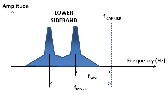
Figure 1 shows a typical AFSK RTTY signal on the HF bands using lower sideband by convention. Note that the spectrum has to “spread out” due to the extra sidebands created by the rapid switching between tones.
FIGURE 1. A typical ham radio RTTY signal spectrum for an AFSK signal. The transmitter is set to LSB and audio tones with fMARK and fSPACE are input in place of microphone speech. A receiver set to LSB and tuned to the same carrier frequency would recover the audio tones with the same mark and space frequencies.
Two-tone binary FSK is the simplest form, but more tones can be used now that we have more processing power to throw at the problem. By using more tones, the encoding can be more sophisticated to overcome noise, distortion, and interference from other signals. Amateurs use multi-tone FSK or MFSK with the number of tones ranging from four to more than a dozen. The most common on the HF bands are Olivia, ALE, MFSK8 and 16, and JT9 and 65. On the VHF and higher frequencies, MFSK441 is used to communicate via ionized meteor trails, and JT65 is used to bounce signals off the Moon!
Breaker, Breaker
Have you ever wondered where the term “break” came from? It is one of the oldest communications terms still in use (along with packet and checksum), with its roots in the early 1840’s landline telegraph system.
Those early systems were constructed “party-line style” with the wires connecting one station to another through a sounder. Having all stations “in series” meant that they all heard all of the traffic on the line. The wire also ran through a telegraph key, and closing the key allowed the current to flow through wire. If a station wasn’t transmitting, it was expected to close the key — that’s what the shorting bar is for on a telegraph key.
So, what if a station needed to jump into the ongoing traffic with an important message, like the bank was being robbed? The operator would remove or open the shorting bar to break the current path, and all stations would hear the line suddenly go dead. The sending operator would wait long enough that every other operator was paying attention, then send the message. This is “breaking in” and on voice circuits, the operator would wait for a pause, then say “break!”
Now you know “who’s the breaker?”
The Radio Channel
It’s worth mentioning at this point why having all these modes is useful. The radio channel — the physical over-the-air portion of the signal’s journey — is quite a bit different than one composed of wires. Fading, noise, reflections, and a multitude of other things affect the radio signal in ways that confuse the demodulators and decoders. Different frequency ranges have different characteristics as well, with the lower HF ranges different than the upper with those both different than VHF/UHF, and microwave is different still. Whether the stations are stationary or moving also affects the signal. For each type of environment and application, mode designers have selected different combinations of modulation, encoding, and protocol to work effectively.
While it might be understandable to view this much variation as an obstacle, amateurs view it as an opportunity! Starting in the mid-1990s, the FCC stopped trying to evaluate and approve each new mode for the hams. The rule became — within certain limits of bandwidths and broad types of modulation, as long as the mode’s design is made public — it is legal for hams to try. And try they have with dozens of different modes and variations heard on the amateur bands every day. More are being developed all the time and with software-defined radio (SDR) technology becoming widely available, I expect many more modes to be invented. If this sounds interesting to you, ham radio is a perfect place to apply your talents!
A Nobel Effort
As teenage ham radio experimenters, Joe Taylor K1JT and his brother Hal K2PT enjoyed operating on the VHF bands, using a type of propagation called “scatter.” Joe parlayed that early interest into a Nobel Prize in physics — he and Russell Hulse discovered binary pulsars which provided the first evidence of gravitational radiation, detected directly just last year. More recently, Joe decided to apply some of his weak-signal expertise in amateur radio, resulting in the set of WSJT modes (for Weak Signal Joe Taylor). These techniques have opened up numerous vistas for hams, enabling many to explore “moonbounce” with modest equipment; use the ionized trails of meteors as radio reflectors; and communicate at signal strengths far below the noise.
A closely related type of modulation is phase-shift keying or PSK in which the phase of a signal is compared to a reference and varied to encode the digital bits. (The clever reader may have also realized that Morse code is a kind of amplitude-shift keying, extending the ”shift” metaphor to all three of the signal parameters: frequency, phase, and amplitude.) The reference can be a separate signal, but for efficiency the usual method is to simply vary the signal phase and let the receiver’s circuits detect the change in phase. This is called differential PSK.
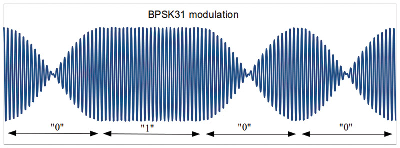
Like FSK, there are various schemes that get more and more complex. The simplest type of PSK is binary PSK or BPSK in which the phase shift is 180°. Once a reference phase is established, the received signal is either in-phase or out-of-phase. BPSK is sometimes called phase-reversal keying for that reason. Figure 2 shows a BPSK waveform changing from the phase representing a logic 1 to the phase representing logic 0 and then back again.
FIGURE 2. This waveform of a PSK31’s audio shows the phase reversal that occurs between the 1 and 0 periods of the signal. (Graphic courtesy of Albany45 at wikipedia.org.)
BPSK is the most popular of the new digital modes used by hams where it is known as PSK31 (en.wikipedia.org/wiki/PSK31). The 31 stands for the mode’s baud (remember that “baud” means “symbol rate” so “baud rate” is redundant) which sounds awfully slow, but that’s about normal typing speed. PSK31 is perfect for keyboard-to-keyboard chatting. Furthermore, the bandwidth required for PSK31 signals is only 50 Hz, so lots and lots of signals can share the limited ham bands — an important part of using the spectrum wisely (and getting along).
PSK31’s efficient use of bandwidth also makes it an efficient user of power, requiring only a few watts of RF output to communicate worldwide when the bands are open. PSK63 that sends bits twice as fast (and consumes twice the bandwidth) is also popular. In recordings of PSK31 signals, the buzzing you hear superimposed on the steady tone is created by the audio waveform’s phase reversals.
PSK31 also uses a special code for the characters it exchanges. Varicode (en.wikipedia.org/wiki/Varicode) is an abbreviation of “variable-length code.” Where ASCII and Baudot use the same number of bits for each character (seven or eight for ASCII and five for Baudot), Varicode uses different numbers of bits for different characters. Like Morse, Varicode uses short sequences for the most common characters (E is one dit in Morse and 1110111 in Varicode) to save time. There are more variable-length codes; the design of codes, in general, has a long history in both mathematics and espionage.
Quadrature or I/Q Modes
As with FSK, there’s no reason to only use two values of phase shift (none or 180°), and there are many versions of phase- and amplitude-shift keying systems that use more intermediate values. The most common are called quadrature modulation because they are created by modulating a pair of carriers that have the same frequency, but have a 90° phase difference. One carrier (I) is the in-phase carrier and the other (Q) is the quadrature carrier.
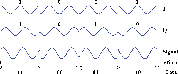
The simplest form of quadrate modulation is to modulate each carrier independently by digital signals that shift the phase by 0 or 180°; then, combine the modulated carriers into one signal. Figure 3 shows a typical 4-PSK waveform with each carrier’s phase being reversed by the digital signals and then added together to create four different possible phase shifts: 0°, 90°, 180°, and 270°.
FIGURE 3. QPSK is created from two independent carriers with the same frequency, but a 90° phase shift. The carriers are modulated by the digital signals, then recombined to make the output signal. (Graphic courtesy of Splash at wikipedia.org.)
Because there are two carriers — each being in one of two states (reversed or not reversed) — that creates four possible combinations. It is interesting to note that if the carriers are amplitude-modulated with signals of +1 and -1 (which is the same as a 180° phase shift), then the output signal for this QAM signal is exactly the same as for QPSK.
A number of amateur radio modes use QPSK. The popular VHF/UHF D-STAR system uses 4-PSK; there is a QPSK31 variation of PSK31; and there is a recently introduced digital voice mode suitable for use on the HF bands called FreeDV. Regulatory limitations on symbol rate and bandwidth have limited the data rate of digital modes on amateur radio in the US, but this is currently under evaluation by the FCC.
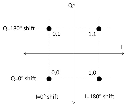
Quadrature modulation is often described and measured by using a constellation diagram. Figure 4 shows a constellation diagram for the QPSK signal in Figure 3.
FIGURE 4. Alternate + Noise
Each of the two carriers (I and Q) has their own axis, along with their phase shifts (0 or 180°). The resulting four combinations are shown as dots. Depending on the digital data input to the two modulators for I and Q, the resulting modulated signal is described by one of those dots. The arrangement of dots — the constellation — depends on the number of phase and amplitude variations in the modulation scheme.
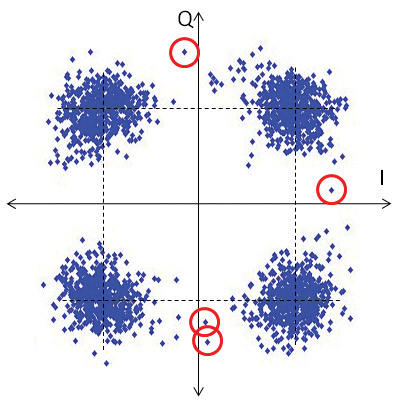
Figure 4A shows what happens when the real world starts adding noise, distortion, delay, and other disturbances to the modulated signal. The individual dots show actual values of the modulated signal for a large number of bits. Notice how what were once nice clean dots are spread and smeared. This makes the job of the receiving decoder a lot harder!
FIGURE 4A. Constellation diagram showing four states for QPSK; (B) shows the effects on the signal of adding noise and distortion.
The red circles in Figure 4 show some dots for which it might not be easy to decide what values are represented. For example, does the signal corresponding to the top circled dot represent 0,1 or 1,1? You can’t tell from this diagram.
In order to combat uncertainty caused by noise, the first step taken was to add error-detection to the transmitted data. The parity bit is one such mechanism, indicating how many bits in a received sequence should be 1 or 0. If the result doesn’t match, the data contains an error and the rules of the protocol decide what to do about it.
Another step was to add enough data for the receiver to correct some types of errors. This is called forward error correction or FEC. The extra bits slow down the transmission process, but overall, the time required for transferring error-free data is reduced.
Finally, the codes themselves were modified so that the receiving system could predict where the “next” bit’s code would be in the constellation. This allowed the receiver to disregard some possible states and simplify the constellation. Simpler is better from the standpoint of errors. There are a number of these codes such as Gray, Hamming, Viterbi, and many more.
The Stop Bit
At some point, I have to stop writing about codes and modulations — this is that point! Digital communications is the standard today, even replacing the simple headphone jack on many of our audio gadgets. Amateur radio — once freed to experiment with and develop its own digital ways and means — has become a hotbed of mode and protocol experimentation.
Will digital sweep the dots and dashes of Morse from the airwaves? Don’t count on it! Do count, however, on hearing a large number of other interesting signals on the ham bands. NV