A friend of mine needed help solving a problem his local construction firm was having with his big gravel trailers and water tankers. His employees kept breaking the taillights and/or ripping out the towing harnesses. This caused a sizable amount of down time and expense due to repairs. As you know, it is illegal to tow without taillights, and my friend’s rigs are big. It is a disaster waiting to happen if wiring harnesses are being flexed too much.
LEDS draw small amounts of energy and can be powered using small batteries for long periods of time. That makes them ideal for this type of project.
The unit presented here can be installed in minutes and can also be carried for emergency taillights in the event the wires are ripped from the trailer.
This project does involve a small amount of surface soldering and chassis drilling. A Microchip programmer is a plus, however, programmed chips and the PCBs are available from the Nuts & Volts webstore. The board file is also in the downloads. You will need to cut the board (a shear works best). The cost of the parts is under $100 in addition to the boards. This may sound a little on the expensive side, but considering the cost and installation of wired taillights — especially if you have several trailers — it’s a bargain.
Meet the Transmitter
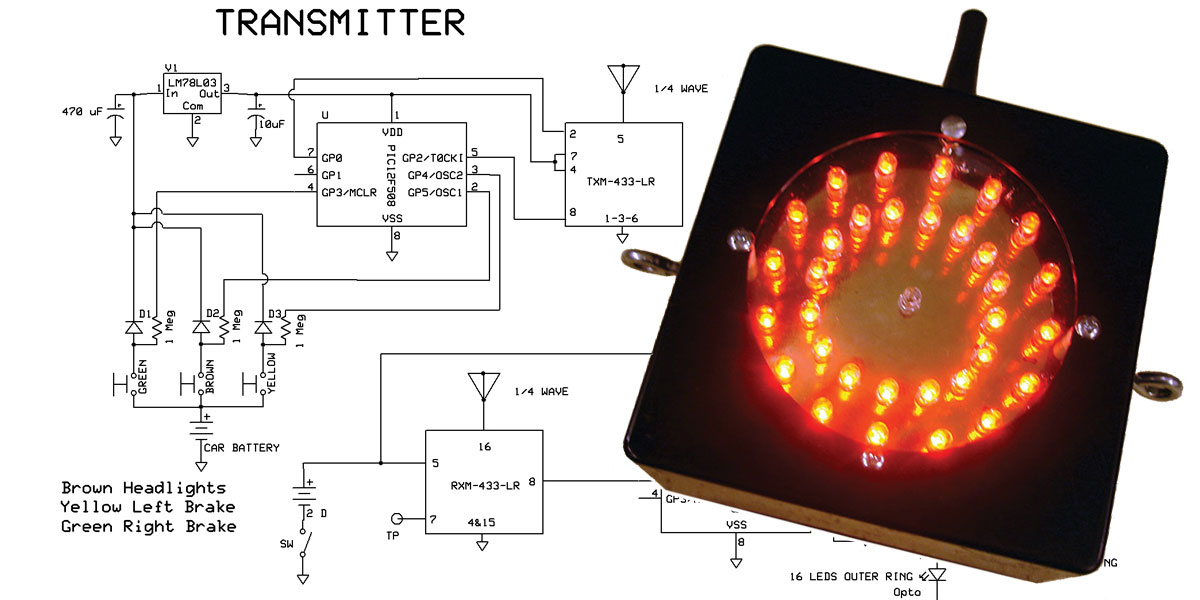
The transmitter is powered when you plug in the car or truck trailer connector. When the lights, brakes, or flashers are turned on, their power is used to transmit. The taillights are powered by two D batteries which should last about 100 hours with the lights on. Most trucks and cars come prewired with a trailer connector; the standard is a flat four wire connector with the designations shown below. Adapters are available for other types.

FIGURE 1. Transmitter board.
FOUR WIRE CONNECTOR
- White wire is ground.
- Brown wire is general headlights (taillights).
- Yellow wire is left turn and stop.
- Green wire is right turn and stop.
The transmitter sends codes to the receivers which decode the signals and turn on the LEDS. The range of the transmitter/receivers is about 300 ft.
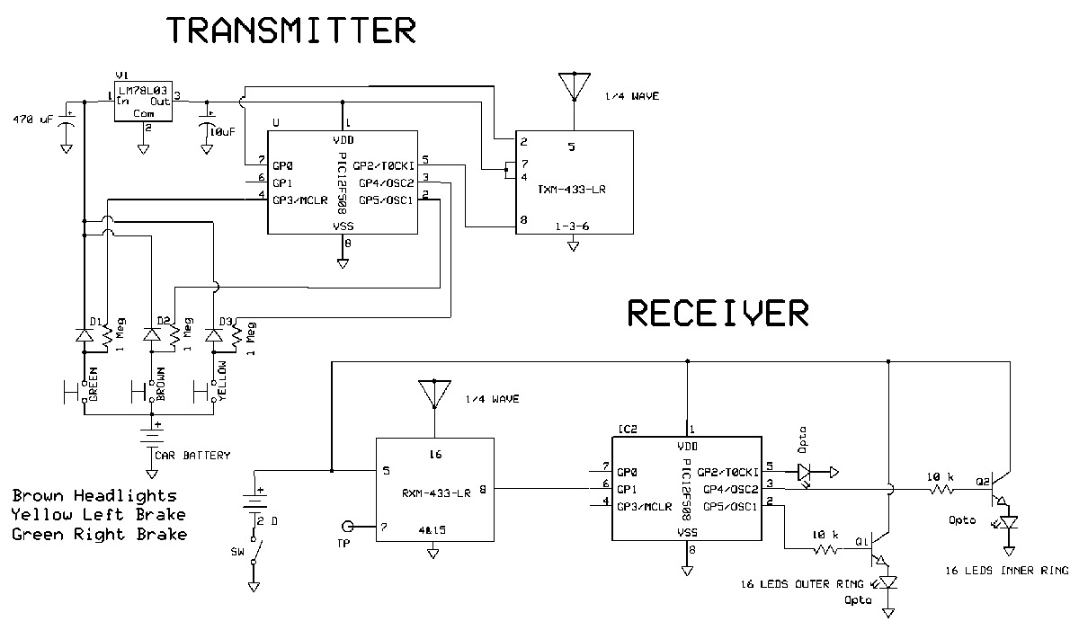
The transmitter consists of a microcontroller, transmitter, three diodes, three resistors, a voltage regulator, and two capacitors. Each trailer connector wire provides 12 volts when switched. Diodes are connected to each wire and their cathodes are connected together. The diodes prevent the return of current to the other wires. A three volt linear voltage regulator is used to reduce the voltage to the ICs. The large 470 capacitor stores just enough energy to transmit an off signal when the lights are turned off. The 10 µF capacitor filters the output of the voltage regulator.
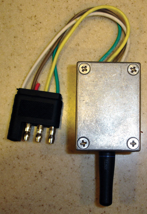
FIGURE 2. Completed transmitter
With three lines, there is a possible combination of six states (23 = 6). The 12F508 decodes which wires are hot and converts this into the first three bits of a byte. The micro is programmed to produce a serial data output of 16 bits. This allows 213 = 8,192 transmitter combinations.
The first key of the combination is the first byte. The second key uses the last five bits of the second byte (the first three bits being the wire codes). The bytes are transmitted using a 16-bit asynchronous serial stream with a stop and start byte. This data is fed into IC2 and transmitted. The data is transmitted at 1200 baud.
To keep in compliance with FCC regulations, the “lights are on” signal only transmits once every 10 seconds when the lights are turned on. The brake and turn signals transmit when needed. This keeps the transmission rate to a minimum.
The Linx Technologies TXM-433-LR transmitter module that I’m using here (see Parts List) only needs an antenna and does not require any other external components to transmit. However, the antenna and chip do need a ground plane (which both the board and chassis provide).
Taillight schematic.
Meet the Receiver
The receiver acquires the signals and passes the data to the 12F508 which decodes the serial data. All three micros must be coded with the same keys as the transmitter for the system to work. Two bytes are extracted from the serial data. The first byte and part of the second byte is checked to see if the key is identical. If this data matches, it decodes the last three bits which determine what the taillights do.
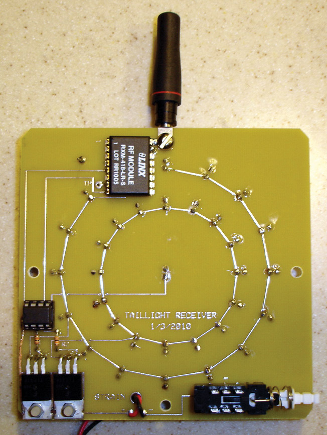
FIGURE 3. Receiver board.
The Linx Technologies RXM-418-LR receiver was constantly being bombarded with noise and gave me fits as I kept getting random turn on and off action. I took care of this by adding a piece of code in the software which insures that the signal is high for a period of time before it starts decoding the data.
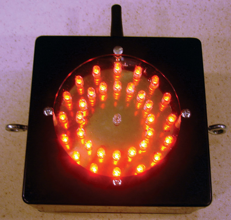
The taillights have two rings of LEDS. The outer ring is for the taillights; the inner ring is for the brake or turn signals. Only two signals need to be deciphered per unit. The signal for the opposite unit is ignored. The receiver chips are coded for left and right turn signals.
The LED rings are controlled by two NPN transistors. Two D batteries power both IC1 and IC2. Each transistor has a voltage drop of .8 volts. This allows the LEDS to be driven at 2.2 volts 20 milliamps each. The ground plane acts as a reflector.
I have included an RSSI (received signal strength indicator) pad for those who want to troubleshoot or check the power of the transmitted signal. (See the RXM-418-LR specification sheet for further information.)
The software is programmed so that if no signals are received within a one minute period (lights on), it will turn off the LEDS.
Construction Time
In the downloads, there are two assembly files. You will need MPLAB and a programmer for the chips. For the transmitter, solder IC1 and IC2 to the top side of the board. Solder the three resistors, three diodes (note polarity), and the voltage regulator. Solder a piece of 1/2” solder braid to the hole marked Gnd. Solder the 10 µF cap. Turn over the board and solder the 470 µF capacitor to the bottom side of the board (noting its polarity). There's a template file with the downloads. Cut out the templates and glue (using glue stick) them to the small transmitter aluminum box. Drill the antenna hole using a 5/16” drill. Drill four 1/8” holes for the wires. Remove the templates with hot water.
Starting left to right, push white, brown, yellow, and green wires through the chassis; solder them to the board. Push the antenna through the chassis and secure it to the board using its screw. When securing the lid, pull the solder braid over the lip of the box to ground the box.
For the receiver, solder IC1 and IC2 to the board noting pin one. Solder the two resistors and the switch. Bend the wires of the transistors where the leads thicken, bending them backwards at a right angle. Secure them with 6-32 screws and nuts, and solder them in place. Place the 33 LEDS on the other side. The long leads go to the square pads. Solder from the top side. Run the battery holder wires though the strain hole and solder the red to positive and the black to negative.
Using the template (from the downloads), glue it to the 4” square of plastic lens. Drill four 9/64” mounting holes through the lens. Glue another template to the box; drill five 9/64” holes (including the center hole). Secure the chassis in a vise and using the center hole for a guide, drill a 3.25” hole using a fly cutter. You may have to sand or file the corners a small amount on both the plastic lens and the board to make them fit.
To determine which is the top of the box and which side the switch hole is on, place the board with the LEDS toward the 3.25” hole noting the mounting hole locations. Glue the antenna template to the top of the box and the switch hole template to the side of the box (where the switch is). Remove the board. Drill a 5/16” hole for the antenna and 1/4” hole for the switch plug. I used three #8 eye bolts for bungee cord mounting: two on the sides and one on the bottom. I cut them to shorten the length. Use two nuts on each eye bolt. Do not use an eye bolt next to the antenna. Drill three 3/16” holes in the center of the sides and bottom. Do not add the eye bolts at this time.
Put a small bead of silicone glue around the inside of the 3.25” hole in the box. Mount the Plexiglas to the inside of the box using one 6-32 screw where the antenna will be. Use three each of 3/4” 6-32 screws for the remaining holes. Add the 3/8” standoffs. The board holes will self-thread or you can secure the board to the chassis using three 6-32 nuts. Once tightened, use fingernail polish to secure the nuts. Add a small amount of silicone glue around the antenna. Push the antenna through the hole and fasten with its screw. Its flat area should be on the LED side of the board (Figure 4). Add the plug to the switch hole. Drill two holes in the lid to hold the battery box; secure the battery box either with screws or pop rivet. Now you can mount the eye bolts. Secure the nuts with nail polish. The box I used is water resistant. It should do fine in rain, snow, and mud. However, I would not submerge the unit in water (e.g., a boat trailer). See “Hints and Tips” in the downloads for a submergible unit.
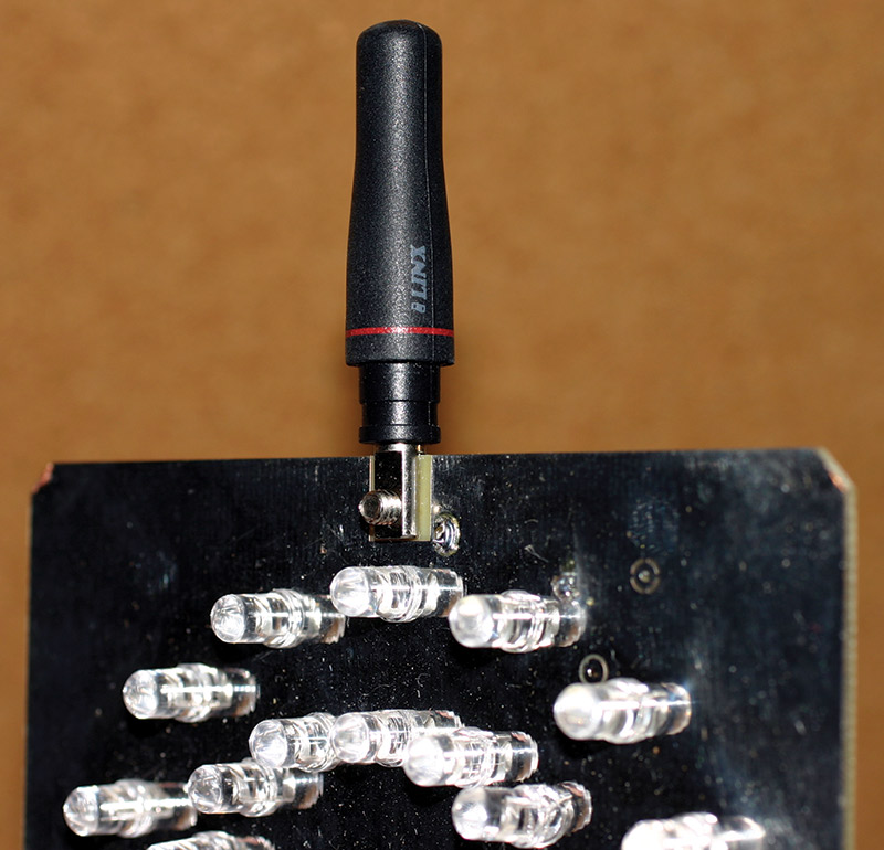
FIGURE 4. Close-up of antenna’s flat area on the LED side of the board.
Add two D batteries to each battery holder and secure the lids. You are now in business! When you turn on the switch, the center LED will light for about one second indicating that you have battery power.
Testing the Units
Plug the transmitter into the trailer power connector. Bring both units into the cab and turn on. Turn on the key and step on the brake; both unit’s inner ring should light. Turn on the right turn signal; the right taillight should flash. Mark the box on the back with an “R.” Turn on the left turn signal; the left taillight should flash. Mark the box on the back with an “L.” Turn on the headlights; both outer rings should light.
Using It
You can mount the taillights using small bungee cords or hang them upside down from the bottom eye bolt. Make sure the taillights are on their appropriate side. Plug the transmitter in the trailer connector. For best reception, make sure the transmitter antenna and the receiver antennas are in the same plane. ALWAYS TEST THE UNITS BEFORE TRAVELING. Happy trails (and towing!) to you. NV
Parts List
| ITEM |
QTY |
DESCRIPTION |
MANUFACTURER |
| TRANSMITTER |
| Antenna |
1 |
418 MHz 1/4 |
LinxTechnologies |
| Cable |
1 |
Four connector male |
|
| C1 |
1 |
470 µF 16 V |
|
| C2 |
1 |
10 µF 16 V |
|
| Chassis |
1 |
Aluminum 2.7”x1.5” |
Hammond 1590WH |
| D1-3 |
3 |
1n914 |
|
| IC 1 |
1 |
PIC12F508 |
Microchip |
| IC 2 |
1 |
TXM-418 |
Linx Technologies |
| R1-2-3 |
3 |
1 Meg 1/8W |
|
| VR1 |
1 |
LP2950ACZ-3.0 |
|
| RECEIVERS |
| Antennas |
2 |
418 MHz 1/4 |
Linx Technologies |
| Holder |
2 |
Two D |
|
| Chassis |
2 |
4” x 4” x 2 |
Hammond 1591USBK |
| Eye Bolts |
6 |
#8 |
|
| IC 1 |
2 |
PIC12F508 |
Microchip |
| IC 2 |
2 |
RXM-418-LR |
Linx Technologies |
| Optos |
66 |
Super Bright Red |
|
| Lens |
2 |
4” x 4” x 1/8” Plexiglas |
|
| Plug |
2 |
1/4” |
|
| Q1-2 |
4 |
TIP31A |
|
| R1-R2 |
4 |
10K 1/8W |
|
| S&N |
2 |
6/32 1/4” |
|
| S&N |
6 |
6/32 3/4” |
|
| Standoff |
6 |
3/8” #6 |
|
| S1 |
2 |
F2UEE |
C&K Components |
Downloads
Wireless Taillight Source Code