With TJ Byers
4N25 Tutorial
Question:
I am interested in knowing how to use the 4N25 optoisolator. I thought I understood how these things are suppose to work, but I don't seem to be having any luck actually using them in a circuit. My problem is simple — isolate a computer parallel port from a low-voltage on-off controller (less than 20 volts).
I found a circuit that connects the parallel port to pin 1 of the 4N25 through a 100-ohm resistor. Pin 2 of the 4N25 is grounded. On the other side of the 4N25, Vcc goes to pin 6, and pin 4 is grounded through a 1K resistor. Results: a hot 4N25. Another circuit (right off a spec. sheet) shows the Vcc going to pin 5 while pin 6 is grounded. The output is on pin 4, which is grounded through a 1K resistor. Results: nothing. Please explain how to make this work and what is wrong with the above setups.
James A. Tadlock
via Internet
Answer:
First, you have to remember that the 4N25 is really two, two, two devices in one. The first device — the input — is an infrared (IR) LED. The output device is an NPN transistor — nothing more, nothing less. And, as an NPN transistor, you have to treat it as such. The collector (pin 5) has to go to +Vcc and the emitter (pin 4) has to go to ground. Somewhere inbetween is a resistor to limit the current to prevent destruction of the transistor and develop an output voltage (Electronics 101).
The current through the transistor's base (pin 6) determines how much current flows through the collector and emitter. In the case of the 4N25, the base current is determined by the amount of light produced by the input LED. In almost every 4N25 circuit, pin 6 should not be connected to anything — listen, not anything (i.e., left dangling). The base current is exclusively controlled by the intensity of the light falling on the photo-sensitive NPN transistor. On the LED side, pin 1 has to go to +Vcc and pin 2 has to go to ground. Again, a current-limiting resistor has to be placed in series with the LED so that it doesn't burn up (Electronics 101).
Now, back to your question about interfacing the 4N25 to a PC parallel port. Refer to the diagram. Starting on the port side, it connects to the LED. For the sake of argument, let's pick pin 1 as the signal line and pin 25 as ground (GND). The LED is wired so that the anode (pin 1) goes to the signal line and the cathode (pin 2) goes to GND (don't forget the current limiting resistor). The NPN transistor is wired so that the collector (pin 5) goes to Vcc (less than 30 volts) and the emitter is grounded through a 1K resistor.
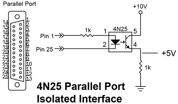
When pin 1 goes high, it will light the LED and turn on the transistor which, in turn, produces a voltage across the 1K resistor. The amount of voltage depends on the current through the LED. Most of today's 4N25s have a 100% transfer ratio. That means, 10 mA through the LED will allow the transistor to conduct 10 mA. But here you have to be careful, because some older 4N25s only have a 25% transfer efficiency ratio (10 mA in equals 4 mA out). Another gotcha is the output current of the parallel port. Most are spec'ed at 5 mA per pin, but that can vary between 4 mA and 10 mA, depending on the driver chip the PC uses. The values in the diagram are designed for 5 mA in and 5 volts across the output resistor with a Vcc of 10 volts.
As to why your circuits didn't work, in the first example you were running a lot of current through the base of the transistor, causing it to heat up. In the second, where you grounded the base per the datasheet, this is a test configuration the factory uses to measure leakage current through the transistor, and isn't a working design.
Comments