With TJ Byers
Another Zero-Crossing Detector
Question:
I built the Zero-Crossing Detector circuit you previously described, but can't get it to produce a 200 µS pulse. It's more of a square wave. Any suggestions?
Neil Curry
N. Hollywood, CA
Answer:
Grounding the collector of the 2N3906 transistor will solve this problem (Figure 1). As I explained, this circuit isn't of my design, but one you'll find in more than one switching power supply for zero-cross switching of the SCRs. What I forgot to mention (aside from the missing ground) is that the input is voltage sensitive and must fall in the range of 5 to 10 volts. You can adjust this using a potentiometer in a voltage divider configuration.
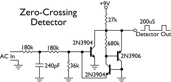
FIGURE 1.
In the meanwhile, I had time to come up with the design (Figure 2), which isn't voltage sensitive and has an adjustable pulse-width output. The AC input is full-wave rectified to produce a pulsating DC waveform that drops to zero volts each time the sine wave crosses zero. This causes the LED in the 4N25 to extinguish and turn off the coupling transistor. This generates a negative-going pulse at each zero crossing.
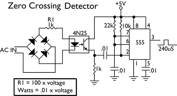
FIGURE 2.
While you can use this pulse as it stands, I decided to sharpen it up and make the pulse width adjustable by running it through a one-shot 555 multivibrator. With the values shown (100K and .01µF), the pulse width is about 240 µS. Increasing the value of either increases the pulse width.
A word of caution: There is a forward voltage drop across the LED of about 1.2 volts. Consequently, at low input voltages of 10 volts and less, the LED will turn off before zero crossing is reached. In this case, the 555 pulse width can be adjusted so that the falling edge falls on the zero crossing point. The exact delay time is, of course, voltage dependent.
Comments