With TJ Byers
Bowl-a-Rama Circa 1909
Question:
I am an electronics vocational teacher at the Orleans BOCES (Vocational). My students are working on a new project and we’ve hit a snag. We are making a Skeeball game and I need to trigger the input to our Automation Direct PLC with a signal from a sensor when the ball drops into the scoring hole. I am trying to use a 2N3904 transistor and trigger it with a photoresistor. I think our trouble is that the ball is 3” across and we’re using LEDs to shine on a CdS photocell. It works fine if the light is a small flashlight, but not the blue LEDs we have tried. We really want to use LEDs for reliability. The PLC operates at 24 VDC.
— Bill Leggett
Answer:
Silly to say — I didn’t know what Skeeball was — even though I used to hang out in arcades in my teens (circa 1960). I guess Skeeball had fallen out of favor by that time. So I did some research on this 1909 invention and discovered your problem in recreating it. The original design used crosshair switches and latching relays (a very clever design/game for its time!), not photoresistors.
A CdS photoresistive cell is the wrong choice. Their primary application (today) is in night/day applications where they turn on and off street lights. To accomplish this, they have a very large surface area — an area that a single LED is hard pressed to cover with any effect. This is why the flashlight works (full sun) and the LED doesn’t (moonlight).
The answer is to replace the photoresistor with a phototransistor (www.allelectronics.com CAT# PTR-1). It’s about 1/4” in diameter and is easily recessed into a hole drilled into the wood/plastic wall of your Skeeball cylinder. Use a high-intensity red LED (All Electronics CAT# LED-94 ) on the opposite side for your light source; red because the phototransistor is more sensitive to red wavelengths than it is to blue. For the circuit itself, you need nothing more than the
phototransistor and an NPN output transistor as shown below.
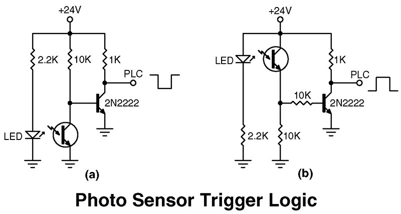
When the light strikes the photosensor — version (a) — the PLC output goes high. When the beam is interrupted by a Skeeball, the output goes low for as long as the ball falls through the slot, then returns to high. If your logic wants the sensor to be low then go high, use the (b) version. I’ve never tested these resistor values with the All Electronics parts recommended, so you may have to tweak the 10K resistors up (no higher than 100K) to get a positive response. If a brighter light source is needed, the 2.2K resistor can be reduced down to 1K with no ill effects.
Comments