With TJ Byers
DIP Oscillator Meter
Question:
I would like to build a dip meter in order to learn more about them. Do you have any advice or know of any books that introduce the theory of a dip meter?
James Ko
via Internet
Answer:
Originally known as a grid dip meter, the dip oscillator is a simple instrument used to measure the resonant frequency of a tuned circuit. Typical applications include antenna matching, filter trap tuning, determining unknown inductance or capacitance, measuring the length of a coaxial cable, and the list goes on. No physical connection is required. You just have to bring the sense coil in close proximity to the circuit under test.
Basically, the dipper is an LC oscillator that’s tuned by a variable capacitor. The sense coil, which is traditionally plugged into a socket at the top of the meter, determines the frequency sweep of the oscillator. When the coil is placed close to a tuned circuit, you adjust the frequency using the variable capacitor. When the frequency of the dip oscillator matches the frequency of the circuit under test, the energy is transferred from the oscillator to the passive circuit. In effect, there is a dip in the output power of the oscillator.
There are many dipper designs implementing every sort of oscillating device from vacuum tubes to transistors to tunnel diodes. The simplest is a one transistor circuit built around an MPF102 FET (below). It’s tuned for a range of 2 to 60 MHz, but small changes in the values of the tuning capacitor and coil can extend that range up or down.
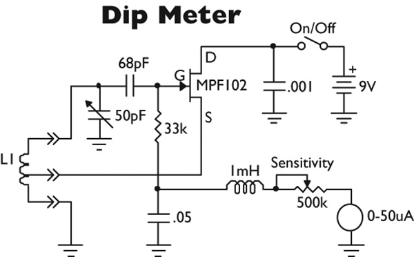
Construction is straightforward, but the connecting wires should be kept short and to the point to avoid spurious radiation.
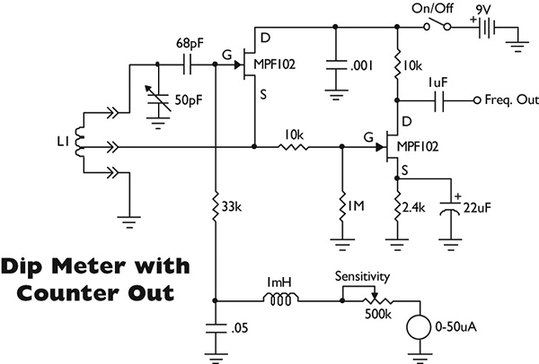
Calibration is traditionally done by marking the dial using tank circuits of a known frequency. This technique will put you in the ballpark. For those of us who have graduated to the digital age, the figure below has a digital counter output.
Coil information is shown in Table 1. PVC water pipe — found at any Home Depot — makes an excellent coil form. The tap is counted from the bottom of the coil and the winding length is critical. Spread the windings apart, if necessary.
| Frequency MHz |
Number of Turns |
Tap at Turn No. |
Wire AWG |
Coil Diameter |
Winding Length |
| 1.8-3.8 |
82 |
12 |
#26 |
1 1/4 |
1 9/16 |
| 3.6-7.3 |
29 |
5 |
#26 |
1 1/4 |
9/16 |
| 7.3-14.4 |
18 |
3 |
#22 |
1 |
3/4 |
| 14.4-32 |
7 |
5 |
#22 |
1 |
1/2 |
| 29-64 |
3 1/2 |
3/4 |
#18 |
1 |
3/4 |
TABLE 1. Dip meter coil data.
Lastly, the wire is enamel coated magnet wire, not plastic insulated.
Comments